

Page 1
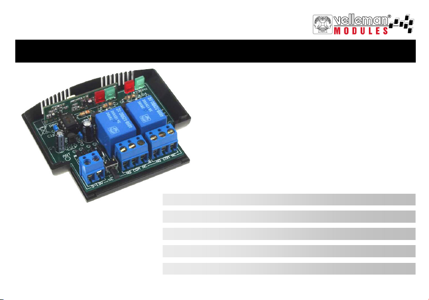
ONE CHANNEL DUAL OUTPUT RECEIVER
VM119
r
u
o
h
t
i
w
e
s
u
r
o
f
M
V
a
r
t
R
8
1
1
r
e
t
t
i
m
s
n
One channel dual output receiver 3
1-kanaals ontvanger met dubbele uitgang 8
Récepteur monocanal à double sortie 13
1-Kanal-Empfänger mit do ppelte m Ausgang 18
Receptor monocanal de doble salida 23
Page 2
1
2
6
7
8
9
See also connection diagram on page 28
3 4
5
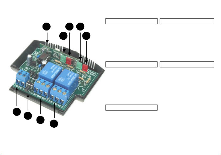
Description
-1- Receiver module
-2- LED 2 : output "1" indicator
-3- LED 1 : Status indicator
-4- LED 3 : output "2" indicator
-5- LED 4 : Status indicator
-6- Power supply
-7- Setup button
-8- output "1"
-9- output "2"
Description
-1- Module récepteur
-2- LED 2 : Indication du sortie "1"
-3- LED 1 : indication du statu
-4- LED 3 : Indication du sortie "2"
-5- LED 4 : indication du statu
-6- Alimentation
-7- Bouton-poussoir ‘Setup’
-8- sortie "1"
-9- sortie "2"
Descripción
-1- Módulo de recepción
-2- LED 2 : Indicación para el canal 1
-3- LED 1 : indicación del estado
-4- LED 3 : Indicación para el canal 2
-5- LED 4 : indicación del estado
-6- Conexión de alimentación
-7- Pulsador ‘Setup’
-8- salida "1"
-9- salida "2"
Beschrijving
-1- Ontvangst module
-2- LED 2 : uitgang "1" indicatie
-3- LED 1 : statusindicatie
-4- LED 3 : uitgang "2" indicatie
-5- LED 4 : statusindicaties
-6- netvoeding aansluiting
-7- Setup drukknop
-8- uitgang "1"
-9- uitgang "2"
Beschreibung
-1- Empfängermodul
-2- LED 2 : Ausgang "1" Anzeige
-3- LED 1 : Status-Anzeige
-4- LED 3 : Ausgang "2" Anzeige
-5- LED 4 : Status-Anzeige
-6- Spannungsversorgung
-7- 'Setup’ druckknöpfe
-8- Ausgang"1"
-9- Ausgang "2"
Page 3
Safety and warning instructions
WARNINGS
All repairs should be executed by qualified technicians.
Avoid the installation of the module in locations with standing or running water or excessi ve humidity. Indoor use only !
Handle the module gently and c arefully. Dropping it can damage the circuit board and case.
Never exceed the protection limit values indicated in the specifications.
As safety requirement vary, please check with your local authorities.
No objects or liquids should be allowed to penetrate the housing.
Disconnect the module from the AC power before connecting new devices.
Wipe the device with a dry and clean cloth. Do not use detergents or other liquids that may damage the housing.
Keep the device away from children.
Facilitate the operation of the device by familiarising yourself with its adjustments and indications.
Velleman modules are not suitable for use or as part of life support systems , or systems that might create hazardous situations of kind.
Repair under warranty is only possible with date and proof of purchase.
WARRANTY
This pro duct is gua rante ed against defects in co mponents and c onst ruction fro m the mo ment it is purchase d and for a per iod o f TWO YEAR starting from the date of sale. This
guarantee is only valid if the unit is submitted together with the original purchase invoice. VELLEMAN components Ltd limits its responsibility to the reparation of defects or,
as VELLEMAN components Ltd deems necessary, to the replacement or reparation of defective components. Costs and risks connected to the transport, removal or placement o f the pr oduct , or any other costs direc tly or indire ctly connec ted to the repa ir, will not be rei mburse d by VELL EMAN components Ltd. VELLEMAN components Ltd will
not be held res ponsible fo r any damages caused by t he malfunctio ning of a unit .
SAFETY INSTRUCTIONS
3
Page 4

Specifications & features
SPECIFICATIONS & FEATURES
For use with our "VM118R" transmitter
Using multiple receivers of this type in combination with our 8 channel transmitter, will allow you to control remotely up to 8
devices at different places. e.g. Perfectly suited for hide –away control situations, for demonstrations, home use...
A single transmitter key-press activates two independent outputs. Each output can be configured as toggle, pulse or pulse
with timer. This allows you to e.g. Start two different timers, have a pulsed and a timed output, have two galvanically
separated outputs, etc
Features
easy setup and transmitter ‘learning’, no jumper settings
toggle or pulse function selectable per output
unique feature: dual output
easy fixation
pulse function can have turn off timer
up to 31 different "VM118R" transmitters or transmitter buttons can be stored
‘All clear’-function
LED indicators for outputs and functions
Specifications
• for use with "VM118R" (or "K8058" kit) RF transmitters
• relay contacts NO / NC: 2A max. each
• Operation frequence : 433MHz.
• selectable timers/output: 0.5s, 5s, 30s, 1min, 5min, 15min, 30min and 60min
• open field range of up to 30m possible
• power supply: 9 to 12V AC or DC / 100mA max
• dimensions: 80x70x25mm / 3,14 x 2,75 x 0,98"
4
Page 5
Configuration
CONFIGURING K8058 / VM 118R AS 'PULSE'
ATTENTION: Each channel of the VM118R (or K8058) used to control the VM119 must be set in “PULSE” mode. Keys
set to operate in toggle mode will not be accepted by the VM119.
Each relay can be individually configured to behave as a toggle (ON/OFF) or as a pulse contact.
Hold ‘shift’ until the LED on the remote lights to enter the ‘set-up’-mode then press ‘1’ to enter output setup mode :
Press a button (1..8) to change the function of the corresponding output:
Next, press ‘shift’ several times until the LED turns off to leave setup mode (*).
LED flashes once: pulse mode,
•
• LED flashes tw ice: toggle mode.
NOTE : Use an external antenna when reception is not sufficient or when the module is located near a metal object.
Solder some flexible wire (length of min. 30cm) to the ANT point on the PCB and pull the wire out of the housing. This
wire will serve as an antenna.
TO LEARN A REMOTE (BUTTON):
At power-on, LD1 will flash a # of times, hereby indicating that the unit is operational. Next, LD4 will turn-on.
At first power-on, the unit will respond to channel(1)/button(1) of the K8058/VM118R transmitter. Make sure the transmitter
buttons are configured as 'pulse'.
5
Page 6

Configuration
1. Hold 'setup'-button. LD1 turns on.
2. Hold a remote button (1..8)
3. LD4 will light when the button has been stored
4. Release all buttons
Repeat steps 1 trough 4 to learn other remote buttons or remotes.
31 transmitters or transmitter-buttons can be stor ed.
If the memory is full, both LD1 and LD4 will flash rapidly.
TO REMOVE ALL STORED REMOTES FROM MEMORY AND TO RETURN TO FACTORY DEFAULTS
1. Turn off the power.
2. Hold 'setup'-button.
3. Turn on power. LD1 and LD4 will start flashing
4. Release 'setup' when LD1 and LD4 stop flashing
This process takes about 10 seconds.
If the button is released before the leds stop flashing, the memory will not be cleared.
The unit will now respond to the default code only.
6
Page 7
CONFIGURATION OF LEFT AND RIGHT RELAY OUTPUT
1. Push 'setup'-button repeatedly to configure either left relay (LD2 lights) or right relay
(LD3 lights).
2. Confirm your selection with a long push (LD4 flashes 3 times).
The selected relay will remain ON.
3. Push 'setup'-button a number of times, depending on the desired mode (see table).
At each press, LD1 will flash a # of times, indicating the current mode.
4. Confirm with a long push (LD4 flashes 3 times).
The selected relay will turn off and the unit is ready for use.
flashes Mode
The unit will return to normal operation when left idle for 10s. The current mode will not be
changed.
If necessary, repeat sequence for the remaining channel.
Factory defaults: left relay-output (CH1): 0.5s timer right relay-output (CH2): 1h timer
USE
Pressing a transmitter button will operate both outputs simultaniously.
Each relay will behave according to the selected mode.
In '0.5s timer'-mode, the relay will remain on for as long as the remote button is held.
In 'ON/OFF'-mode, the relay will toggle between ON and OFF every time the remote button is pushed.
1
2
3
4
5
6
7
8
9
ON/OFF
0.5s timer
5s timer
30s timer
1min timer
5min timer
15min timer
30min timer
1h timer
Use
7
Page 8
Veiligheidsaanwijzingen en waarschuwingen
WAARSCHUWING
Reparaties mogen uitsluitend uitgevoerd worden door vakkundige personen.
Installeer de module niet op plaatsen met staand of stromend water of in ruimtes met een te hoge vochtigheidsgraad.
Binnengebruik enkel!
Vermijd een ruwe behandeling. Stoten of laten vallen kunnen ernstige schade aanbrengen.
Overschrijdt nooit de opgegeven veiligheidswaarden in de specificaties.
Vermits de veiligheid vereisten verschillen van plaats tot plaats, zorg daarom dat Uw montage voldoet aan de plaatselijke
geldende vereisten.
Let op dat er geen voorwerpen of vloeistoffen in het toestel dringen.
Zorg ervoor dat de netspanning altijd uitgeschakeld is bij het aansluiten van nieuwe toestellen.
Houdt vooral kinderen uit de buurt van het toestel dit ter veiligheid van hun zelf.
Zorgt ervoor dat u met alle bedieningselementen vertrouwd raakt, wanneer U met het toestel zal werken.
Velleman modules zijn niet geschikt voor gebruik in of als gedeelte van systemen welke levensfuncties in stand houden of
systemen welke gevaarlijke situaties van gelijk welke aard kunnen veroorzaken.
Herstelling onder garantie is enkel mogelijk met aankoopbewijs.
WAARBORG
Dit pr odukt i s gewaa rbor gd wat be tre ft gebre ken in mat eri alen e n vakmanschap o p het ogenblik v an de a ankoo p en dit gedurende een perio de van TW EE JAAR vanaf de
aankoop. De waarborg geldt enkel indien het produkt voorgelegd wordt samen met het orig ineel aankoop bewijs. De verplicht ingen v an VEL LEMAN C OMPO NENTS N.V.
beperken zic h tot het he rst ellen v an def ect en of , naa r vrije keuze v an VEL LEM AN COMP ONENTS N.V., tot het vervange n of he rst ellen van defecte onderdelen. Kosten en
risico’s va n trans port; het wegne men en terugpla ats en van he t produkt , eve nals o m het eve n welke a ndere koste n die rechtstre eks of onr echt stre eks ver band houde n met de
herstelling, worden niet door VELLEMAN COMPONENTS N.V. vergoed. VELLEMAN COMPONENTS N.V. is niet verantwoordelijk voor schade van gelijk welke aard,
veroorzaakt door het falen va n een product.
VEILIGHEID SAANWIJZINGEN
8
Page 9
Technische gegevens & eigenschappen
TECHNISCHE GEGEVENS & EIGENSCHAPPEN
Voor gebruik met onze "VM118R" zender
Gebruik een aantal van deze ontvangers samen met onze 8-kanaals zender en u kunt tot 8 toestellen op afstand besturen.
Deze ontvanger is uiterst geschikt voor ingebouwde toestellen, demonstraties, gebruik thuis…
Een enkele druk op de knop van de zender activeert twee onafhankelijke uitgangen. Elke uitgang kan geconfigureerd
worden als schakeling, impuls of impuls met timer. Dit laat toe om bv. twee timers te starten of verkrijgt u een uitgang met
impuls en een met timer, twee galvanisch gescheiden uitgangen, enz.
Kenmerken
eenvoudige configuratie en aanleerproces van de zender, geen jumper-instellingen
selecteerbare schakel- of pulsfunctie per uitgang
unieke eigenschap: dubbele uitgang
eenvoudige bevestiging
pulsfunctie met uitschakeltimer
geheugen tot 31 verscheidene "VM118R" -zenders of zenderdrukknoppen
"Alles wissen"-functie
Ledaanduidingen voor de uitgangen en de functies
Specificaties
• voor gebruik met "VM118R" (of "K8058" kit) RF-zenders
• NO/NC relaiscontacten: 2A max. elk
• werkingsfrequentie : 433MHz.
• selecteerbare timers per uitgang: 0.5s, 5s, 30s, 1min, 5min, 15min, 30min en 60min
• bereik tot 30m (ononderbroken gezichtslijn)
• voeding: 9 tot 12V AC of DC / 100mA max.
• afmetingen: 80 x 70 x 25mm
9
Page 10
Configuratie
K8058 / VM118R CONFIGUREREN ALS 'PULSE'
AANDACHT: Elk kanaal van de VM118R (of K8058) dat gebruikt wordt om de VM119 mee aan te sturen, moet
geconfigureerd zijn als ‘PULSE’-modus. Toetsen die als wisselcontact ingesteld staan, worden niet geaccepteerd door de
VM119.
Elk relais kan afzonderlijk geconfigureerd worden om te werken als wisselcontact (ON/OFF) of als momentcontact.
Houd ‘shift’ ingedrukt tot de LED op de afstandsbediening oplicht om aan te geven dat de instelmode is geactiveerd.
Druk vervolgens op ‘1’ om de instelmode voor de uitgang te activeren:
Druk op een knop (1...8) om de functie van een desbetreffende uitgang te wijzigen:
•
LED knippert 1 x : momentcontact.
• LED knippert 2 x : wisselc ontact.
Om de instelmode te verlaten, moet u herhaaldelijk ‘shift’ indrukken tot de LED dooft (*).
NOTA : Indien de ontvangst ontoereikend is, of als de module zich in de omgeving van metaal bevindt kan een externe
antenne worden gebruikt.Soldeer een stuk soepel snoer van min. zo’n 30cm aan het punt ‘ANT’ op de print, en breng dit
snoer buiten de behuizing. Dit snoer doet dan dienst als externe antenne.
EEN ZENDER(TOETS) AANLEREN:
Bij het onder spanning brengen knippert LD1 een aantal keer, wat aangeeft dat de unit operationeel is, vervolgens licht LD4
op. Bij het voor de eerste maal onder spanning brengen zal de unit enkel reageren op kanaal (1)/toets (1) van de K8058/
VM118R zender. Let erop dat de zendertoetsen als 'puls' geconfigureerd zijn.
10
Page 11

1. Hou 'setup'-toets ingedrukt. LD1 licht op.
2. Hou de zendertoets die U wenst aan te leren ingedrukt.
3. LD4 licht op wanneer de toets in het geheugen opgeslagen is.
4. Laat alle toetsen los.
Herhaal stappen 1. tot 4. om andere toetsen aan te leren.
Tot 31 zenders of zendertoetsen kunnen aangeleerd worden.
Wanneer het geheugen vol is, zullen LD1 en LD4 snel knipperen.
OPGESLAGEN ZENDERS WISSEN EN TERUGKEREN NAAR DE FABRIEKSINSTELLINGEN
1. Onderbreek de voedingsspanning van de ontvanger.
2. Hou de 'setup'-toets ingedrukt.
3. Schakel de voedingsspanning terug in. LD1 en LD4 knipperen
4. Laat de 'setup'-toets los wanneer LD1 en LD4 doven.
Dit proces neemt ongeveer 10 seconden in beslag.
Indien de toets vroeger losgelaten werd, zal het geheugen niet gewist zijn.
De ontvanger zal nu enkel op de fabriekscode reageren.
Configuratie
11
Page 12

Gebruik
INSTELLEN VAN DE LINKSE EN RECHTSE RELAIS-UITGANG
1. Druk herhaald op de 'setup'-toets om ofwel het linkse relais (LD2 licht op) of het rechtse
relais (LD3 licht op) in te stellen.
2. Bevestig uw keuze met een lange druk (LD4 knippert 3x). Het gekozen relais blijft
ingeschakeld.
3. Druk een aantal keer op de 'setup'-toets, afhankelijk van de gewenste mode (zie tabel).
Bij elke toetsdruk zal LD1 een aantal keer knipperen. Dit geeft de huidige mode aan.
4. Bevestig uw keuze met een lange druk (LD4 knippert 3x). Het gekozen relais schakelt
uit en de unit is terug klaar voor gebruik.
De unit keert terug naar de normale werking indien de 'setup'-toets gedurende 10s niet
bediend werd. De huidige mode blijft ongewijzigd.
Indien gewenst, herhaal de procedure voor de andere relaisuitgang.
Fabrieksinstellingen: linkse relais-uitgang (CH1): 0.5s timer rechtse relais-uitgang (CH2): 1h timer
Aantal x
knipperen
1
2
3
4
5
6
7
8
9
GEBRUIK
Een druk op een zendertoets zal beide uitgangen simultaan activeren.
Elke uitgang zal zich gedragen naargelang de gekozen mode.
In '0.5s timer'-mode zal het relais aangetrokken blijven zolang de zendertoets ingedrukt blijft.
In 'AAN/UIT'-mode zal het relais omschakelen telkens men op een zendertoets drukt.
Mode
AAN / UIT
0.5s timer
5s timer
30s timer
1 min timer
5 min timer
15 min timer
30 min timer
1h timer
12
Page 13

Consignes de sécurité et mises en garde
AVERTISSEMENT
Toute réparation doit être exécutée par du personnel qualifié.
Évitez l’installation de ce module à proximité d’eau courante ou dormante ou à une endroit avec un taux d’humidité
trop élevé.
Evitez les manipulations brutales. Un chute pourrait endommager le boîtier ou les plaque et pourrait causer des défauts.
Ne jamais excéder les valeurs limites de protection indiquées dans les spécifications.
Etant donné que les exigences en matière de sécurité varient d’un lieu à l’autre, vous devez vous assurer que votre montage
satisfait aux exigences.
Aucun objet ou liquide ne peut pénétrer le boîtier.
Débranchez le module avant de connecter des appareils nouveaux.
Essuyez l'appareil à l'aide d'un chiffon propre et sec. Evitez donc l'usage de détergents ou d'autres liquides, comme ceux-ci
endommageraient le boîtier.
Gardez l'appareil hors de la portée d'enfants.
Familiarisez-vous avec tous les réglages et indications de l'appareil afin de faciliter l'opération.
Les modules Velleman ne conviennent pas pour une utilisation dans ou comme parties de systèmes servant à assurer des
fonctions de survie ou des systèmes pouvant entr aîner des situations dangereuses, de quelque nature qu‘elles soient.
CONSIGNES DE SECURITE
La réparation sous garantie est uniquement possible avec la preuve de l‘achat !
GARANTIE
Ce pro duit es t gara nti cont re les défaut s des co mposantes et de fabri cati on au moment de l’a chat , et ce po ur une péri ode d’ UN AN à par tir de la date d’achat. Ce tte gara ntie
est unique ment va lable s i le produit est acco mpagné de la preuve d’achat originale. Les obligations de VELLEMAN S.A. se limitent à la réparation des défauts ou, sur seule
déci sion de VELLE MAN S.A., au re mplacement o u à la répar ation des pi èces dé fectueuses . Les frais e t les risques de transpor t, l’e nlèvement e t le re nvoi du produit , ai nsi que
tous autres frais liés directement ou indirectement à la réparation, ne sont pas pris en charge par VELLEMAN S.A. VELLEMAN S.A. n’est pa s respo nsable des dégâ ts, que ls
qu’ils soie nt, provoqués par le mauva is fo nctio nnement d’un produit.
13
Page 14

Caractéristiques et données techniques
CARACTÉRISTIQUES ET DONNÉES TECHNIQUES
Pour usage avec notre émetteur "VM118R"
L'utilisation de plusieurs récepteurs de ce type en combinaison avec notre émetteur à 8 canaux vous permettra de contrôler
jusqu'à 8 appareils à distance. Convient particulièrement pour la commande d'appareils non visibles, démonstrations, usage
domestique…
Une simple pression sur le bouton de l'émetteur actionnera deux sorties indépendantes. Chaque sortie peut être configurée
comme commutation, impulsion ou impulsion avec minuterie, ce qui vous permettra d'actionner deux minuteries, ou d'avoir à
disposition une sortie à impulsion et une à minuterie, deux sorties à séparation galvanique, etc.
Caractéristiques
configuration et processus d'apprentissage de l'émetteur simples, pas de réglages du pont
fonction de commutation ou d'impulsion sélectionnable par sortie
caractéristique unique: double sortie
fixation facile
fonction d'impulsion avec minuteur de désactivation
mémoire jusqu'à 31 différents émetteurs "VM118R" ou boutons émetteurs
fonction "Tout effacer"
indicateurs LED pour les sorties et les fonctions
Spécifications
• pour usage avec des émetteurs RF VM118R (ou en kit K8058)
• contacts relais NO / NC: 2A max. chaque
• opération 433MHz
• minuteurs sélectionnables par sortie: 0.5s, 5s, 30s, 1min, 5min, 15min, 30min et 60min
• portée jusqu'à 30m (rayon visuel sans obstacles)
• alimentation: 9 à 12V CA ou CC / 100mA max.
• dimensions: 80 x 70 x 25mm
14
Page 15

Configuration
CONFIGURES K8058 / VM118R COMME 'IMPULSION'
ATTENTION: Chaque canal du VM118R (ou du K8058) utilisé pour commander le VM119 doit être configuré en mode
"PULSE". Les touches configurées comme contact inverseur ne seront pas reconnues par le VM119.
Chaque relais peut être configuré de manière différente pour faire fonction de commutateur d’inversion (ON/OFF) ou de
contact d'impulsion.
Maintenez enfoncé ‘shift’ jusqu’à ce que la LED sur la commande à distance s’allume pour indiquer l’activation du
mode de configuration. Ensuite, enfoncez ‘1’ pour activer le mode de configuration de la sortie:
Enfoncez une touche (1...8) pour modifier la fonction d’une sortie:
La LED clignote 1 x: contact d' impulsion.
•
• La LED clignote 2 x: commutateur d’invers ion.
Pour quitter le mode de configuration, enfoncez la touche ‘shift’ à plusieurs reprises jusqu’à ce que la LED
s’éteigne (*).
REMARQUE : Si la réception est insuffisante ou lorsque le module se trouve à proximité d’un objet métallique, il est
possible d’utiliser une antenne externe. Soudez un bout de fil souple d’une longueur de min. 30cm au point ANT du CI.
Sortez le fil hors du boîtier. Ce fil servira donc d’antenne.
APPRENTISSAGE D’UN (BOUTON) ÉMETTEUR
Lors de la mise sous tension, LD1 flashera un nombre de fois, indiquant que l’unité est en état de marche. Ensuite, LD4
s’allume. Lors de la première mise sous tension, l’unité ne réagira qu’au canal (1)/bouton (1) de l’émetteur K8058/VM118R.
Veillez à ce que les boutons de l’émetteur soient configures comme ‘impulsion’ (consultez la notice du K8058/VM118R).
15
Page 16

Configuration
1. Maintenez enfoncé le bouton 'setup'. La LED LD1 s’allume.
2. Maintenez enfoncé un bouton émetteur (1..8)
3. LD4 s’allume dès la mémorisation du bouton.
4. Relâchez tous les boutons.
Répétez les étapes ci-dessus pour apprendre d’autres boutons.
Possibilité de mémoriser 31 émetteurs ou boutons d’émetteurs.
A mémoire pleine, LD1 et LD4 flasheront rapidement.
EFFACER TOUS LES ÉMETTEURS MÉMORISÉS ET RÉTABLIR LA CONFIGURATION D’USINE
1. Coupez l’alimentation.
2. Maintenez enfoncé le bouton 'setup'.
3. Rétablissez l’alimentation. LD1 et LD4 commencent à flasher.
4. Relâchez le bouton 'setup' dès que LD1 et LD4 s’arrêtent de flasher.
Ce processus dure environ 10 secondes.
Si vous relâchez le bouton avant que les LEDs aient terminées de flasher, la mémoire ne sera pas effacée.
Le récepteur ne répondra qu’au code d’usine.
16
Page 17

CONFIGURATION DE LA SORTIE R ELAIS GAUCHE ET DROIT
1. Enfoncez le bouton 'setup' à plusieurs reprises pour configurer soit le relais gauche
(LD2 s’allume) ou le relais droit (LD3 s’allume).
2. Confirmez votre sélection en maintenant enfoncé le bouton (LD4 flashes 3 fois). Le
relais sélectionné reste enclenché.
3. Enfoncez le bouton 'setup' à plusieurs reprises en fonction du mode désiré (voir
table). A chaque pression LD1 flash un certain nombre de fois, indiquant le mode
actuel.
4. Confirmez en maintenant enfoncé le bouton (LD4 flashes 3 fois). Le relais
sélectionné se déclenche et l’unité est prête à l’emploi.
L’unité revient à l’opération normale si le bouton ‘setup’ ne pas enfoncé dans un délai
de 10s. Le mode actuel restera inchangé.
Si nécessaire, répétez la séquence pour le canal qui reste.
Configuration d’usine: sortie relais gauche (CH1): minuterie 0.5s sortie relais droit (CH2): minuterie 1h
clignotements Mode
MARCHE/ARRET
1
0,5s timer
2
5s timer
3
30s timer
4
1 minute timer
5
5 minutes timer
6
15 minutes timer
7
30 minutes timer
8
1 heure timer
9
EMPLOI
En enfonçant un bouton d’émetteur activera les deux sorties simultanément.
Chaque relais se comportera selon le mode sélectionné.
En mode 'minuterie 0.5s', le relais restera enclenché aussi longtemps que le bouton d’émetteur est enfoncé.
En mode 'MARCHE/ARRET', le relais commutera entre MARCHE et ARRET à chaque pression du bouton d’émetteur.
Emploi
17
Page 18

Sicherheits– und Warnhinweise
WARNUNG
Lassen Sie Reparaturen durch Fachleute erfolgen
Installieren Sie das Modul nicht in einer Umgebung mit stehendem oder fließendem Wasser oder in einer sehr feuchten
Umgebung
Gehen Sie behutsam mit dem Modul um. Es fallen lassen, kann die Leiterplatte und das Gehäuse beschädigen.
Überschreiten Sie nie die in den technischen Daten erwähnten Eingangsgrößen.
Sicherheitsvorschriften können sich ändern, bitte beachten Sie die lokalen Vorschriften Ihres Landes.
Schützen Sie die Innenseite des Gehäus es vor Flüssigkeiten und Gegenständen.
Sorgen Sie dafür, dass alles spannungslos ist, ehe andere Geräte anzuschließen.
Nehmen Sie zur Reinigung des Gerätes ein feuchtes Reinigungstuch. Benutzen Sie auf keinen Fall Scheuer- oder Lösungsmittel
Von Kindern fernhalten.
Machen Sie sich mit allen Bedi enungselement vertraut, wenn Sie mit diesem Gerät arbeiten.
Der von Ihnen gekaufte Bausatz ist aber für den Privatgebr auch konzipiert und ni ch für den Eins atz in Lebenserhaltenden
oder Lebensrettenden Systemen oder unter außergewöhnlichen Umweltbedingungen (Ex-systeme) geeinet.
GARANTIE
Dieses Produkt trägt eine Garantie für fehlerhaftes Material oder Verarbeitungsschäden im Moment des Ankaufs. Sie ist ZWEI JAHR gültig ab Ankaufsdatum. Die Garantie
kann nur beans prucht w erden, wenn da s Pro dutk mit de r Originalrechnung abgegebe n wird. Die Verpfli chtunge n der VEL LEM AN COMPO NENTS AG be sc hränken sic h auf
die Aufhebung der Fehler, oder, nach freier Wahl der VELLEMAN COMPONENTS AG , auf den Austausch oder die Reparation der fehlerhaft en Tei le. Ko sten und Risi ken des
Transpo rts ; das E ntfer nen und W iede reins etzen de s Pro dukts, sowie alle a ndere n Koste n die di rekt oder i ndirekt mit der Repara tion i n Verbindung gebrac ht we rden können,
werde n durch di e VELL EMAN COMP ONEN TS AG nicht zurücke rst att et. VEL LEMAN COMPO NENTS AG ist nic ht für Sc häden gle ich w elche r Art, e ntstanden aus der
fehlerhaft en Funkt ion de s Pro dukt, haftba r.
SICHERHEITSHINWEISE
Reparatur unter Garantiebedingungen ist nur bei Vorlage des Kaufbeleges möglich.
18
Page 19

Eigenschaften und T echnische kenndaten
EIGENSCHAFTEN UND TECHNISCHE KENNDATEN
Für Anwendung mit dem "VM118R"-Sender
Verwenden Sie einige dieser Empfänger zusammen mit dem 8-Kanal-Sender und Sie können bis zu 8 Geräte fernbedienen.
Dieser Empfänger eignet sich sehr für Einbaugeräte, Demonstrationen, Anwendung zu Hause, usw.
Mit einem Tastendruck des Senders aktivieren Sie zwei unabhängige Ausgänge. Jeder Ausgang kann als Schaltung, Impuls
oder Impuls mit Timer konfiguriert werden. Dadurch können Sie z.B. zwei Timer starten, einen Ausgang mit Impuls und einen
mit Timer haben, über zwei galvanisch getrennte Ausgänge, usw. verfügen.
Eigenschaften
Einfach konfigurierbar, keine Steckbrückeneinstellungen
Auswählbare Schalt- oder Impulsfunktion pro Ausgang
Einzigartige Eigenschaft: doppelter Ausgang
einfache Befestigung
Impulsfunktion mit Ausschalttimer
Es können bis zu 31 verschiedene "VM118R" -Sender oder Sendertasten gespeichert werden
'Alles Löschen'-Funktion
LED-Anzeigen für die Ausgänge und Funktionen
Technische Daten
• Für Anwendung mit "VM118R" (oder "K8058" Bausatz) RF-Sendern.
• NO/NC-Relaiskontakte: 2A max.
• 433MHz-Betrieb
• Auswählbare Timer pro Ausgang: 0.5 Sek., 5 Sek., 30 Sek., 1 Min., 5 Min., 15 Min., 30 Min. und 60 Min.
• Bereich ohne Hindernisse bis zu 30m
• Stromversorgung: 9 bis 12V AC oder DC / 100mA max.
• Abmessungen: 80x70x25 mm
19
Page 20

Konfiguration
K8058 / VM118R ALS 'PULSE' TASTEN EINSTELLEN
ANMERKUNG: Jeder Kanal des VM118R (oder K8058), der zum Ansteuern des VM119 verwendet wird, soll als
‘PULSE’-Modus konfiguriert werden. Der VM119 akzeptiert keine Tasten, die als Wechselkontakt eingestellt stehen.
Jedes Relais kann individuell als Wechselkontakt (EIN/AUS) oder Momentkontakt konfiguriert wer den.
Halten Sie die ‘Shift’-Taste gedrückt bis die LED der Fernbedienung aufleuchtet um den ‘Set-up’-Modus zu öffnen.
Drücken Sie danach die ‘1’-Taste um in den Einstellmodus des Ausgangs zu aktivieren.
Drücken Sie die Taste (1...8) um die Funktion eines Ausgangs zu ändern::
•
LED blinkt einm al: Momentkon takt
• LED blinkt zweimal: Wechselkontakt
Drücken Sie danach wiederholt die ‘Shift’-Taste bis die LED erlischt um den ‘Set-Up’-Modus zu verlassen (*).
ANMERKUNG : Wenn der Empfang nicht ausreicht oder wenn das Modul sich in der Nähe von Metall befindet, können
Sie eine externe Antenne verwenden. Löten Sie ein Stück Draht (flexibel) von mindestens 30cm am Punkt ‘ANT’ de
Leiterplatte an, und ziehen Sie den Draht aus dem Gehäuse heraus. Dieser Draht dient als externe Antenne.
EINE FER NBEDIENUNG(STASTE) LEHREN
Beim Anschalten wird LD1 einige Male blinken als Zeichen, dass die Einheit betriebsbereit ist. Danach wird LD4 wird
aufleuchten. Beim ersten Anschalten wird die Einheit auf Kanal (1)/T aste (1) des K8058/VM118R Senders reagieren.
Sorgen Sie dafür, dass die Sendertasten als 'pulse' Tasten konfiguriert sind.
20
Page 21

Konfiguration
1. Halten Sie die 'Setup'-Taste gedrückt. LD1 leuchtet auf.
2. Halten Sie eine Taste der Fernbedienung gedrückt (1..8).
3. LD4 wird aufleuchten wenn die Taste gespeichert worden ist.
4. Lassen Sie alle Tasten los.
Wiederholen Sie Schritte 1 bis 4 um andere Fernbedienungstasten oder Fernbedienungen zu lehren.
31 Sender oder Sendertasten können gespeichert werden.
Wenn der Speicher voll ist, werden LD1 und LD4 schnell blinken.
ALLE GESPEICHERTEN FERNBEDIENUNGEN ENTFERNEN UND ZU DEN WERKSEINSTELLUNGEN
ZURÜCKKEHREN
1. Schalten Sie das Gerät aus.
2. Halten Sie die 'Setup'-Taste gedrückt.
3. Schalten Sie das Gerät wieder an. LD1 und LD4 werden blinken
4. Lassen Sie die 'Setup'-Taste los wenn LD1 und LD4 aufhören zu blinken.
Das Verfahren dauert ungefähr 10 Sekunden.
Wenn die Taste losgelassen wird bevor die LEDs zu blinken aufhören, wird der Speicher nicht gelöscht werden.
Die Einheit wird jetzt nur auf den Standardcode reagieren.
21
Page 22

Anwendung
KONFIGURATION DES LINKEN UND RECHTEN RELAISAUSGANGS
1. Drücken Sie wiederholt die 'Setup'-Taste um entweder das linke Relais (LD2 leuchtet auf) oder
das rechte Relais (LD3 leuchtet auf) einzustellen.
2. Bestätigen Sie Ihre Auswahl mit einem langen Druck (LD4 blinkt dreimal). Das selektierte Relais
wird eingeschaltet bleiben.
3. Drücken Sie einige Male die 'Setup'-Taste, abhängig vom gewünschten Modus (seihe Tabelle).
Bei jedem Tastendruck wird LD1 einige Male blinken, als Anzeige des aktuellen Modus.
4. Bestätigen Sie Ihre Auswahl mit einem langen Druck (LD4 blinkt dreimal). Das selektierte Relais
wird ausschalten und die Einheit ist betriebsfertig.
Die Einheit wird zum normalen Betrieb zurückkehren wenn sie 10 Sekunden nicht ungenutzt
bleibt. Der aktuelle Modus wird nicht geändert werden.
Falls nötig, wiederholen Sie diese Sequenz für die übrigen Kanäle.
Werkseinstellungen: linker Relaisausgang (CH1): 0.5Sek. Timer, rechter Relaisausgang (CH2): 1Std. Timer
Blitze Funktion
EIN/AUS
1
0,5Sek. timer
2
5Sek. timer
3
30Sek. timer
4
1 Min. timer
5
5 Min. timer
6
15 Min. timer
7
30 Min. timer
8
1 Stunde timer
9
ANWENDUNG
Ein Drücken einer Sendertaste wird die beiden Ausgänge gleichzeitig bedienen. Jedes Relais wird sich gemäß dem ei ngestellten
Modus verhalten. Im 0.5Sek. Timer-Modus, wird das Relais solange eine Taste gehalten wird, eingeschaltet sein.
Im EIN/AUS-Modus, wird das Relais zwischen dem EIN und AUS-Modus schalten, jedes Mal die Fernbedienungstaste gedrückt
wird.
22
Page 23

Instrucciones de seguridad
AVISOS
El servicio debe ser realizado por personal especializado
No instale el módulo en un lugar con agua estancada o agua corriente, ni en lugares excesivamente húmedos.
Manéjese con cuidado. Dejar c aer el dispositi vo puede dañar el circuito impreso y la caja.
Nunca exceda los valores límites indicados en las especificaciones.
LAS MEDIDAS DE SEGURIDAD
Las exigencias en materia de seguridad varían de un lugar a otro. Asegúr ese que el montaje realizado sea conforme a las
exigencias en vigor de su localidad.
Asegúrese de que no penetren objetos o líquidos en el dispositivo.
Desconecte el módulo de la red antes de conectar nuevos dispositivos .
Limpie el dispositi vo con un paño húmedo. Evite el uso de productos químicos abrasivos, solventes o detergentes.
Manténgase lejos de niños.
Siga cuidadosamente todas las instrucciones y familiarícese con los ajustes al operar este dispositivo.
Los modulo Velleman no son adecuados para una utilización dentro o corno sistema destinado a garantizar funciones para
sobrevivir o sistemas conllevando situaciones peligrosas sea cual su naturaleza.
La reparación en garantía sólo es posible con el ticket y la fecha de compra.
GARANTÍA
Este pr oduct o est á gara ntizado cont ra def ectos de componentes y co nstruc ción a parti r de su adqui si ció n y durante un perí odo de TRES AÑO a par tir de la fec ha de venta.
Esta ga rantía só lo es váli da si la unida d se entrega junto con la factura de compra original. VELLEM AN COMPONENTS Ltd. limita su res ponsabili dad a la repar ación de los
defectos o, si VELLE MAN COMPONE NTS Lt d. lo est ima nece sari o, a la sust ituci ón o repa raci ón de los compo nente s def ectuo sos. Los gastos y riesgos con res pecto al
trans port e, el des montaje o la inst alaci ón del di sposi tivo, o c ualquie r otro gasto directa o indire ctament e vincula do co n la reparación, no será reembolsado por VELLEMAN
COMPO NENTS Lt d. VEL LEMAN COMPONE NTS Ltd no re sponde rá de ningún da ño causado por el mal func iona miento de la uni dad.
23
Page 24

Especificaciones y Características
ESPECIFICARTIONES Y CARACTERÍSTICAS
Para utilizar con el emisor "VM118R"
El uso de varios receptores de este tipo junto con el emisor de 8 canales le permitirá controlar hasta 8 aparatos a distancia.
Particularmente es apto para controlar aparatos invisibles, demostraciones, uso doméstico, etc.
Una sencilla presión en la tecla del emisor activará dos salidas independientes. Es posible ajustar cada salida como
conmutación, pulso o pulso con temporizador, lo que le permitirá activar dos temporizadores, o tener una salida con pulso y
una con temporizador, o disponer de dos salidas galvánicamente separadas, etc.
Características
configuración y procedimiento de aprendizaje sencillos del emisor, sin ajustes jumper
Función de conmutación o pulsos seleccionable por salida
única característica: doble salida
Anillo de fijación
Función de pulsos con temporizador de desactivación
es posible guardar hasta 31 diferentes emisores "VM118R" o teclas emisores
Función de borrar "All clear"
Indicadores LED para las salidas y las funciones
Especificaciones
• para el uso con emisores RF "VM118R" (o en kit "K8058")
• contactos relé NO / NC: 2A máx. cada uno
• operación 433MHz
• temporizadores seleccionables por salida: 0.5s, 5s, 30s, 1min, 5min, 15min, 30min y 60min
• alcance sin obstáculos hasta 30m
• alimentación: de 9 a 12V AC o DC / 100mA máx.
• dimensiones: 80x70x25 mm
24
Page 25

Configuración
CONFIGURAR K8058 / VM118R COMO 'PULSO'
ATENCIÓN : Asegúrese de que cada canal del VM118R (o del K8058) utilizado para controlar el VM119 esté ajustado
en el modo "PULSE". El VM119 no reconoce las teclas ajustadas como contacto inversor.
Es posible configurar cada relé de otra manera para hacerle funcionar como conmutador de palanca (ON/OFF) o contacto
momentáneo.
Mantenga pulsado ‘shift’ hasta que el LED del mando a distancia se ilumine para indicar la activación del modo de
ajuste. Luego, pulse ‘1’ para activar el modo de ajuste de la salida:
Pulse una tecla (1...8) para modificar la función de una salida:
Para salirse del modo de ajuste, pulse la tecla ‘shift’ varias veces hasta que el LED se apague (*).
El LED parpadea 1 x: contacto momentáneo.
•
• El LED parpade a 2 x: conmutador de palanca.
ATENCIÓN : Si la recepción es insuficiente o si el módulo está cerca de un objeto metálico, es posible utilizar una antena
externa. Suelde un hilo flexible de una longitud de mín. 30cm al punto ANT del circuito impreso. Saque el hilo fuera de la
caja. Este hilo servirá de antena.
PROGRAMAR UN TRANSMISOR
LD1 parpadeará varias veces al activar el aparato. Esto indica que el aparato está funcionando. Luego LD4 se iluminará. Al activar
el aparato por primera vez reaccionará sólo al canal (1) / botón (1) del emisor K8058/VM118R.
Asegúrese de que los botones del emisor estén configurados como ‘pulso’.
25
Page 26

Configuración
1. Mantenga pulsado el botón 'setup'. LD1 se iluminará.
2. Mantenga pulsada un botón del emisor (1..8).
3. LD4 se iluminar á en cuanto el botón haya sido guardado en la memoria.
4. Suelte todos los botones.
Repita los pasos de 1. a 4. para programar otros botones.
Es posible programar hasta 31 transmisores o botones de emisores!
Si la memoria está llena, LD1 y LD4 parpadearán rápidamente!
BORRAR TODOS LOS EMISORES GUARDADOS Y VOLVER A LOS AJUSTES DE FÁBRICA
1. Desactive la alimentación.
2. Mantenga pulsado el botón 'setup'.
3. Vuelva a activar la alimentación. LD1 y LD4 empezarán a parpadear
4. Suelte el botón 'setup' si LD1 y LD4 se apagan.
¡Este procedimiento durará aproximadamente 10 segundos!
¡Al soltar el botón antes de que los LEDs dejen de parpadear, la memoria no estará borrada!
¡El receptor sólo reaccionará al código de fábrica!
26
Page 27

Uso
CONFIGURAR LA SALIDA DE RELÉ IZQUIERDA Y DERECHA
1. Pulse el botón 'setup' repetidas veces para configurar, sea el relé izquierdo
(LD2 se ilumina), sea el relé derecho (LD3 se ilumina).
2. Confirme su elección al mantener pulsado el botón (LD4 parpadea 3 veces).
El relé seleccionado queda activado.
3. Pulse el botón 'setup' repetidas veces, dependiente del modo deseado (véase lista).
Cada vez que pulsa una tecla, LD1 parpadeará varias veces. Esto indica el
modo actual.
4. Confirme su elección al mantener pulsado el botón (LD4 parpadea 3 veces).
El relé seleccionado se desactiva y el aparato está listo para utilizar.
¡El aparato vuelve al funcionamiento normal al no pulsar el botón 'setup' durante
10s. El modo actual permanecerá inalterado!
Si fuera necesario, repita el procedimiento para las otras salidas de relé.
Ajustes de fábrica: salida de relé izquierda (CH1): temporizador 0.5s, salida de relé derecha (CH2): temporizador 1h
parpadeo Modo
1
ENCENDIDO/APAGADO
2
0,5s temporizador
3
5s temporizador
4
30s temporizador
5
1 minuto temporizador
6
5 minutos temporizador
7
15 minutos temporizador
8
30 minutos temporizador
9
1 hora temporizador
USO
Para activar las dos salidas simultáneamente, pulse uno de los botones del emisor.
Cada relé se comportará según el modo seleccionado.
En el modo 'temporizador 0.5s' el relé quedará mientras mantenga pulsado el botón del emisor.
En el modo 'ON/OFF' el relé conmutará entre ON y OFF' cada vez que se pulsa un botón del emisor.
27
Page 28

To control application(s)
Naar de toepassing
A l'application
Zur Applikation
Antenna
9 - 12V AC
or DC
MAINS
NC
NO
NC
NO
COM
COM
28
Page 29

To all resi dents of the Europe an Union
Aan al le ingezetenen van de Eur opese Unie
Aux résidents de l'Union Européenne
An all e Einwohner der Eur opäischen Unio n
A los ciudadanos de la Unión Europea
A todos os cidadãos da União Europei a
A tutti i cittadini dell’Unione europea
NL
FR D ES
UK
IT
PT
Belangrijke milieu-informatie betreffende dit product Dit sy mbool o p het to estel of de verpa kking geeft aa n dat, als he t na zijn le venscyc lus wordt weggewor pen, dit
toes tel sc hade ka n toebrengen aan het mi lieu. Goo i dit toestel ( en eventuele batterije n) niet bij het gewone
huishoudelijke afval; het moet bij een gespecialiseerd bedrijf terechtkomen voor recyclage. U dient dit toestel naar
uw ver deler of naar een loka al recyclagepunt t e brengen. Re specteer de plaatseli jke milieuwet gevi ng.
Heeft u vragen, contacteer dan de plaatselijke autoriteiten inzake afvalverwijdering.
Des informations environnementales importantes concernant ce produit
Important environmental information about this product This symbol on this unit or the package, indicates that disposal of this unit after its lifecycle could harm the environment.
Do not dispose the unit as unsorted municipal waste; it should be disposed by a specialized company for recycling. This
unit should be returned to your distributor or to a local recycling service. Respect the local environmental rules.
If any doubt contact your local authorities about waste disposal rules.
ENG
DUT
Ce symbole s ur l'apparei l ou l'emballage indique que, si l'appareil est jeté après sa vie , il peut nuire à l'environneme nt. Ne
FR
Dies es Symbol a uf dem Pro dukt oder der Verpa ckung zei gt an, da ss die E ntsorgung dieses Produkte s nach sei nem
Lebe nszyklus der Umwelt S chaden zufügen ka nn. Ents orgen Sie die Einhe it (ode r verwe ndeten Bat terie n) nicht als unsortie rtes
Hausm üll; die E inheit o der ver wendeten B atteri en müssen v on einer s pezialis ierten F irma zwec ks Recyc ling entso rgt werd en.
Diese Einheit muss an den Händler oder ein örtliches Recycling-Unternehmen retourniert werden. Respektieren Sie die
örtli chen Umwe ltvors chrifte n.
Wichtige Umwe ltinformationen über dieses Produkt
jetez pas cet appareil (et des piles éventuelles) parmi les déchets ménagers ; il doit arriver chez une firme spécialisée
pour recyclage. Vous êtes tenu à porter cet appareil à votre revendeur ou un point de recyclage local. Respectez la
législation e nvironnementa le locale.
Si vous avez des questions, contactez les autorités locales pour élimination de déchets
D
Falls Zweifel bestehen, wenden Sie sich für Entsorgungsrichtlinien an Ihre örtliche Behörde.
Importantes informaciones sobre e l medio ambiente conce rniente este producto Este símbolo en este aparato o el embalaje indica que, si tira las muestras inservibles, podrían dañar el medio ambiente. No tire
ES
Informação ambiental importante sobre este produto Este s ímbolo, inc luído na u nidade ou pacote, significa que após o seu c iclo de vida de ve prestar a tenção onde o
este aparato (ni las pilas eventuales) en la basura doméstica; debe ir a una empresa especializada en reciclaje. Devuelva este
aparato a su distribuidor o un lugar de reciclaje local. Respecte las leyes locales en relación con el me dio ambiente.
Si tiene dudas, contacte las autoridades locales para la eliminación de residuos
PT
Importanti info rmazioni ambienta li riguardo a questo prodotto Questo simbolo sul prodotto o l’imballaggio indica che è vietato smaltire il prodotto nell’ambiente al termine del suo ciclo
vitale in quan to può essere nocivo per l’ambiente stesso. Non smaltire il pro dotto (o le pile se utili zzate) come rifi uto
urbano indifferenziato ; dovrebbe essere smaltito da un’impresa specializzata nel riciclaggio. Q uesto prodotto dovrebbe
essere restituito al distributo re o ad un’impresa di riciclaggio locale. Rispettare le norme ambientali locali.
vai co locar pois po de danifica r o meio ambient e. Não coloque a unidade ( ou bateria s se uti lizadas ) juntamente com
outros produtos; deve colocar nos recipientes próprios para reciclagem. Esta unidade deve ser entregue ao seu
distribuidor ou colocada em recipiente próprio para reciclagem. Respeite o ambiente!
Em caso de dúvida contacte as autoridades da sua área.
In caso di dubb io, contattare l’amm inistrazione comuna le per informazioni in materia di sma ltimento de i rifiuti.
IT
Page 30

ανακύκλωσης. Η µον άδα αυτή πρέπει να επιστραφεί στον
Til alle innbyggere i Den Europeiske Union
Til alle beboere i den Europæ iske Union (EU)
Kaikille Euroopan Unionin kansalaisille
Do wszystk ich obywateli Uni i Europejskiej
Všem obyvatelům Evropsk é Unie.
Tüm Avrupa Birl iği vatandaşlarına
Προς όλους τους πολίτες της Ευρωπαϊκής Έν ωσ ης
TJ
PL
TR
NO
DK
FIN
EL
Viktig miljöinformation om denna produkt Denna s ymbol på enhe ten eller på f örpackninge n anger att a nvändning av denna e nhet efter dess li vstid kan va ra
SE
skadlig för miljön. Deponera EJ enheten (eller batterierna, om sådana används) som osorterat kommunalt avfall;
det s kall depo neras av e tt prof essionellt bo lag för återvinning. Enheten s kall åt ers ändas till din di stri butör eller till et t
lokalt återvinnings bolag.Re spekt era de loka la best ämmelse rna för åte rvinning.
Vid minsta tv ekan kontakta den lokala myn digheten om vilka bes tämmelser, som gälle r för avfallsdeponer ing.
Viktig miljøinformasjon om dette produktet Dette symbolet på denne enheten eller pakken betyr at enheten kan skade miljøet dersom den kastes etter endt
levetid. Ikke kast enheten (eller batterier dersom disse er brukt) som usortert kommunalt avfall, den bør kastes av et
særskilt firma for gjenvinning. Denne enheten bør returneres til leverandøren eller til en lokal gjenvinningstjeneste.
Respekter det lokale miljøregle mentet.
DK
Kontakt de lokale myndighetene dersom du skulle være i tvil om reglementet for håndtering av avfall
Tärkeää ympäristöä koskevaa asiaa tästä tuotteesta Oheinen symboli tuotteessa tai sen pakkauksessa tarkoittaa sitä, että sen hävittäminen käytön jälkeen saattaa
FIN
Ten sy mbol na ur ządze niu lub opakowaniu oznacza, że wyr zucenie tego ur ządzenia po zużyciu mo głoby zaszkodzić
środowi sku. Urządzeń (lub ba terii, jeżeli były używa ne) nie należy wyrzucać tak ja k nieso rtowany ch odpadków komunal nych.
Powi nna je usunąć wyspecjalizowana firma w celu recyklingu. Urządzenie to należy zwrócić dystrybuto rowi lub mie jscowym
Důležité informace o zpracování odpadů k tomuto výrobku. Tento s ymbol na výr obku nebo jeho o balu znamená , že odpad z v ýro bku po sko nčení doby jeho živ ota může být
škodlivý pro životní prostředí. Nevyhazujte výrobek (nebo případně použité baterie) do komunálního odpadu. Měl by
být předán k recyklaci odborné firmě. Vraťte výrobek vašemu prodejci nebo jej odevzdejte v místním sběrném místě
Ważne informacje o tym produkcie dotyczące środowiska
służbom zajmu jącym się recykli ngiem. Należy przestrzegać lokalnych przepisów dotyczących ochrony środowiska.
vahingoittaa ympäristöä. Älä hävitä tuotetta (tai sen paristoja) lajittelemattoman tai talousjätteen mukana, se on
toimitett ava kierrät yslai tokseen. Tuot e voi daan palauttaa jälleenmyy jälle tai se on toi mitet tava käsitt elyla itoks een. Kunnioita paikallisia ympärist ösäänn öksiä .
W razie wątpliwoś ci w sprawie zasad usuwania odpadów należy zwróc ić się do władz lokalnych.
PL
odpad ů. Dodr žujte místní předpisy pro nakládání s odpady.
V přípa dě pochybnos tí se obraťte s dotazem na prav idla nakládání s od pady na vaše místně příslušné úřady.
Bu ünite deki ya da paketteki bu s embol, bu ünit enin ö mrünü doldur duktan sonr a atılmasının çevreye zarar
verebileceğini belirtmektedir. Üniteyi (ya da kullanılırsa bataryaları) sınıflandırılma mış be lediye çö pü olara k ortadan
Bu ürün hakkında önemli ç evre bilg ileri
kaldırmayınız; özel bir firma tarafından yeni den dönüşüme tabi tutulmak üzere toplanma lıdır. Bu ünite genel
dağıtıcınıza ya da yerel bir yenide n dönüşüm is tasyonuna geri ge tirilmelidi r. Yerel ç evre kuralla rına saygı göster iniz.
Herhangi bir şüphe durumunda, çöp atım kur allar ı hakkında yer el yetkilile rle irt ibat a geç iniz.
TJ
TR
αστικά απόβλητα. Πρέ πε ι να απορριφθεί από εξειδικε υµένη εταιρία
Αυτό το σύµβολο πάνω στη µονάδα ή στη συσκευασία υποδ εικνύε ι ότι η απόρριψη της µονάδ ας µετά το τέλος του κύκλου ζωής
της ενδέχεται να βλάψει το περιβάλλον. Μην απορρίπτετε τη µονάδα (ή τις µπα ταρίες αν είναι χρησιµοποιηµένες) ως µικτά
διανοµέα σας ή σε τοπική υπηρεσ ία ανακύκλωσης. Να σέβεστε τους τοπικο ύς περιβαλλοντικούς κανόνες.
Σηµαντι κές π εριβα λλον τικές πληροφορίες για το προϊόν
Σε περίπτωση αµφιβολίας σχετικά µε τους κανόνες απόρριψης αποβλήτων, επικοινωνήστε µε τις τοπικ ές αρχές.
EL
Page 31

Page 32

ONE CHANNEL DUAL OUTPUT RECEIVER
ONE CHANNEL DUAL OUTPUT RECEIVER
VM119
USER MANUAL
Belgium [Head office] Velleman Components +32(0)9 384 36 11
France Velleman Electronique +33(0)3 20 15 86 15
Netherlands Velleman Components +31(0)76 514 7563
USA Velleman Inc. +1(817)284-7785
Spain Velleman Components +34 954 126800
ONE CHANNEL DUAL OUTPUT RECEIVER
5 410329 386771
Modifications and typographical errors reserved - © Velleman Components nv - HVM119- 2008 - ED1
 Loading...