

Page 1

EIGHT CHANNEL RF REMOTE CONTROL SET
VM118
8-channel RF remote control set 3
8-Kanaals RF afstandsbedieningset 11
Jeu émetteur/récepteur RF 8 canaux 19
8-Kanal-RF-Fernbedienungsset 27
Juego emisor/receptor RF de 8 canales 35
Page 2

FCC information for the USA
This device complies with Part 15 of the FCC Rules. Operation is subject to the following two conditions: (1)
this device may not cause harmful interference, and (2) this device must accept any interference received,
including interference that may cause undesired operation.
If this equipment does cause harmful interference to radio or television reception, which can be determined
by turning the equipment off and on, the user is encouraged to try to correct the interference by one or more
of the following measures:
- Reorient or relocate the receiving antenna.
- Increase the separation between the equipment and receiver.
- Consult the dealer or an experienced radio/TV technician for help.
If the user modifies this unit, and these modifications are not approved by Velleman, the FCC may withdraw
the user’s right to operate the equipment.
Details on the FCC regulation can aslo be found on the internet at http://www.fcc.gov
For questions regarding your product, contact:
Velleman Inc, 7354 Tower Street, Fort Worth, TX 76118
Or head office Velleman:
Legen Heirweg 33, 9890 Gavere
Belgium
FCC approved ID code : NLO8058
Page 3
Thank you for purchasing this module. Please read the instructions carefully to ensure correct and safe use of this device.
WARRANTY
This product is guaranteed against defects in components and construction from the moment it is purchased and for a period of TW O YEAR starting from the
date of sale. This guarantee is only valid if the unit is submitted together with the original purchase invoice. VELLEMAN components Ltd limits its
responsibility to the reparation of defects or, as VELLEMAN components Ltd deems necessary, to the replacement or reparation of defective components.
Costs and risks connected to the transport, removal or placement of the product, or any other costs directly or indirectly connected to the repair, will not be
reimbursed by VELLEMAN components Ltd. VELLEMAN components Ltd will not be held responsible for any damages caused by the malfunctioning of a unit.
CONTENTS :
RECEIVER :...........................................................................................................................................................................................4
FEATURES & SPECIFICATIONS..................................................................................................................................................................4
POWER SUPPLY ............................................................................................................................................................................................ 5
OUTPUT CONNECTION EXAMPLE..............................................................................................................................................................6
TRANSMITTER :................................................................................................................................................................................... 7
FEATURES & SPECIFICATIONS..................................................................................................................................................................7
USE...................................................................................................................................................................................................................8
SETUP..............................................................................................................................................................................................................9
SAFETY AND WA R NIN G INSTR UC TI ON S...................................................................................................................................... 10
READ THE OPERATING AND MAINTENANCE INSTRUCTIONS IN
THIS USER’S GUIDE CAREFULLY.
3
Page 4
Receiver
SPECIFICATIONS & FEATURES
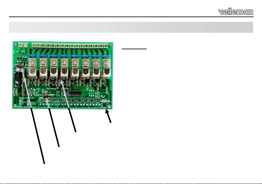
Channel indication LED’s: lights up if the corresponding relay is activated
'Data in' LED: lights up if a transmitter signal is received
Power LED: lights up if correct power is supplied to the card
4
RECEIVER :
FEATURES
eight high quality relay contacts, 5A/230VAC max.
relay outputs are transient suppressed using VDR’s.
LED confirmation on each relay contact.
SPECIFICATIONS
• power: 12Vac / 500mA
Test button, each press will activate the next relay
Page 5
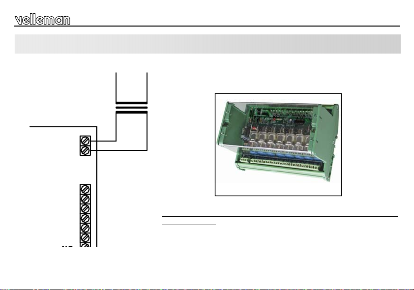
POWER SUPPLY
AC
INPUT
12V
NO
1
NO
2
NO
3
MAINS
1 x 12V / 500mA
Receiver
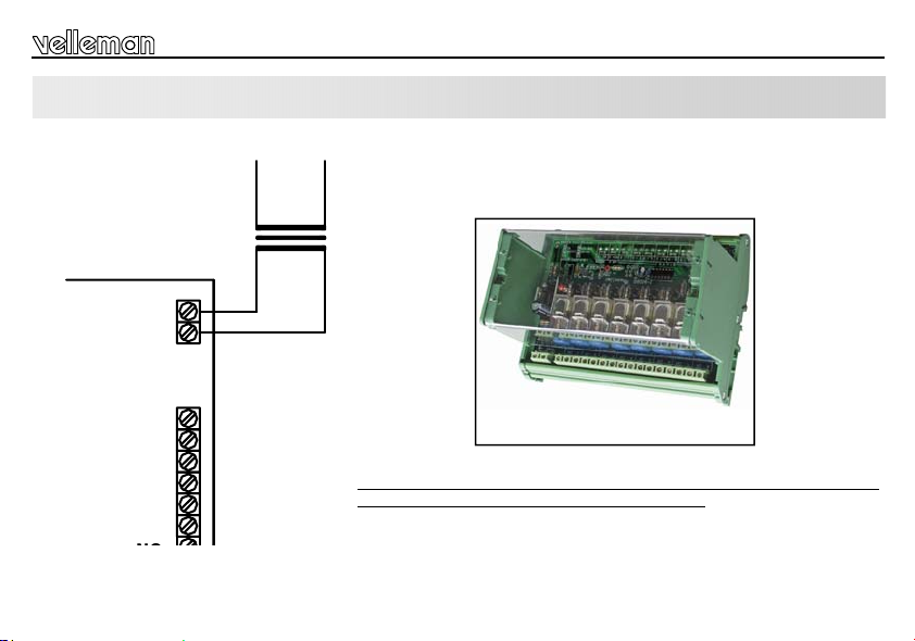
Choose a suitable location for the unit. Probably, the best location is near
the fuse box. An optional enclosure (B8006) is available, for safe installation
of the unit on a DIN rail.
The drawings on the next pages shows connection examples with different
input possibilities.
B8006 Optional Din rail enclosure
Make sure your wiring complies with the local safety requirements.
If doubt, consult a licensed technician !
5
Page 6
Receiver
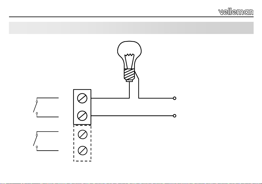
OUTPUT CONNECTION EXAMPLE
NO
1
NO
2
6
230V
N
230V
MAINS AC
L
Page 7
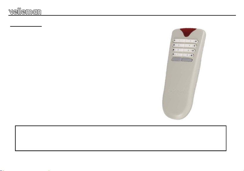
TRANSMITTER :
FEATURES
8 addresses allow the use of multiple receivers
'all clear'- function
Toggle or momentary mode for each key
Open-field range up to 50m
Rubber keypad
SPECIFICATIONS
8 digital encoded channels
433MHz operation
LED function/mode indication
Power supply: 3 AAA batteries (not included)
Dimensions: 150x58x23mm
FCC approved ID code: NLO8058
Velleman hereby certifies that the device VM118 meets the essential requirements and all other relevant
For the complete conformity declaration check out :http://www.velleman.be/downloads/doC/declaration_VM118.pdf
stipulations of directive 1999/5/EG and 1995/5/EC.
Transmitter
7
Page 8

Transmitter
USE
Insert the batteries in the battery
compartment as indicated in figure
and close the compartment.
Remark : Respect your
national and local laws when
disposing of empty batteries.
8
CHANNEL SELECTION
LED
1
3
5
7
• Channels 1..8 can be configured as 'toggle' (on/off) or pulse (see set-up)
• The indicator LED will briefly light when a button is pressed.
• Briefly pressing the shift button turns off all relays.
Note: All settings remain in memory after battery replacement
2
4
6
8
SHIFT
Page 9

Transmitter
SET-UP
(1) Relay action output set-up
Each relay can be individually configured to behave as a toggle (ON/OFF) or as a pulse contact.
Hold ‘shift’ until the LED on the remote lights to enter the ‘set-up’-mode then press ‘1’ to enter output setup mode :
Press a button (1..8) to change the function of the corresponding output:
Next, press ‘shift’ several times until the LED turns off to leave setup mode (*).
(2) Card address selection set-up (see also page 10)
In order to operate multiple units in close proximity without interference, each unit must have a unique address.
8 addresses are available, default address is 1.
Addr LD5 ... LD8
1
2
3
4
5
6
7
8
LED flashes once: pulse mode,
•
• LED flashes twice: toggle mode.
>> > First make sure the card is powered see page 5 !
How to check the current address:
Hold ‘shift’ until the LED lights to enter the ‘set-up’-mode.
Press ‘2’ to display the current address, the relay LED's LD5..LD8 indicate current address (see table).
Next, press ‘shift’ several times until the LED turns off to leave setup mode (*).
How to change the address:
Hold ‘shift’ until the LED lights to enter the ‘set-up’-mode.
Press ‘3’ to allow address change, pressing a button (1..8) will change the address of the remote and the relay card
Next, press ‘shift’ several times until the LED turns off to leave setup mode (*).
If more than one transmitter is used, please repeat point 2 using the other transmitter
(see table).
Attention: All active cards will respond to this comman d. Remove power from cards which do not need to change their address.
(*) NOTE: If no button is pushed for about 15s, the unit will leave ‘setup’-mode automatically.
9
Page 10
Safety & warning instructions
HINT: Return to default card address 1
If an unknown card is used, or the transmitter is not longer at the same address as the card, it is possible to force the card to
address 1.
>> > First make sure the card is powered see page 5 !
How to force to address “1”:
Hold ‘shift’ until the LED lights to enter the ‘set-up’-mode.
Press ‘4’ to force the current address to 1, LED LD8 on the card must light.
Next, press ‘shift’ several times until the LED turns off to leave setup mode.
WARNINGS
All repairs should be executed by qualified technicians.
Avoid the installation of the module in locations with standing or running water or excessive humidity. Indoor use only !
SAFETY INSTRUCTIONS
Handle the module gent ly and c arefu lly . Dro pping it c an damag e t he cir cuit boar d.
Never exceed the protection limit values indicated in the specifications.
As safety requirement vary , pl ease c hec k wit h your local au thoriti es.
Facilitate the operation of the device by familiarising yourself with its adjustments and indications.
Velleman modules are not suitable for use or as part of life support systems, or systems that might create hazardous situations of kind.
Repair under warranty is only possible with date and proof o f purchase .
10
Page 11
Hartelijk dank voor de aanschaf van deze module. Lees de gebruiksaanwijzing aandachtig, zodat u het apparaat op de juiste
manier gebruikt.
WAARBORG
Dit produkt is gewaarborgd wat betreft gebreken in materialen en vakmanschap op het ogenblik van de aankoop en dit gedurende een periode van TWEE
JAAR vanaf de aankoop. De waarborg geldt enkel indien het produkt voorgelegd wordt samen met het origineel aankoop bewijs. De verplichtingen van
VELLEMAN COMPONENTS N.V. beperken zich tot het herstellen van defecten of, naar vrije keuze van VELLEMAN COMPONENTS N.V., tot het vervangen
of herstellen van defecte onderdelen. Kosten en risico’s van transport; het wegnemen en terugplaatsen van het produkt, evenals om het even welke andere
kosten die rechtstreeks of onrechtstreeks verband houden met de herstelling, worden niet door VELLEMAN COMPONENTS N.V. vergoed. VELLEMAN
COMPONENTS N.V. is niet verantwoordelijk voor schade van gelijk welke aard, veroorzaakt door het falen van een product.
INHOUD :
ONTVANGER :....................................................................................................................................................................................12
KENMERKEN & SPECIFICATIES................................................................................................................................................................12
VOEDING .......................................................................................................................................................................................................13
AANLSUITINGSVOORBEELD VOOR DE UITGANG................................................................................................................................14
ZENDER :............................................................................................................................................................................................15
KENMERKEN & SPECIFICATIES................................................................................................................................................................15
GERBUIK........................................................................................................................................................................................................ 16
INSTELLING................................................................................................................................................................................................... 17
VEILIIGHEIDSAANWIJZINGEN EN WAARSCHUW INGEN............................................................................................................ 18
LEES DE GEBRUIKS - EN ONDERHOUDSAANWIJZINGEN VAN DE
HANDLEIDING ZORGVULDIG DOOR.
11
Page 12

Ontvanger
EIGENSCHAPPEN & TECHNISCHE GEGEVENS
Testknop, elke druk op deze knop brengt het volgende relais
in werking.
KanaalLED: licht op wanneer het overeenstemmende relais actief is.
'Data in' LED: licht op wanneer de kaart een signaal van de zender ontvangt.
VoedingsLED: licht op wanneer de kaart de juiste voeding krijgt.
12
ONTVANGER:
EIGENSCHAPPEN
8 hoogwaardige relaiscontacten, 5A/230Vac max.
relaisuitgangen onderdrukken pieken d.m.v. VDRs
bevestiging via LED op ieder relaiscontact
TECHNISCHE GEGEVENS
• voeding: 12Vac / 500mA
Page 13
VOEDING
INPUT
AC
12V
NO
NO
NO
1
2
3
MAINS
1 x 12V / 500mA
Ontvanger
Kies een geschikte locatie voor de installatie van de unit. Waarschijnlijk zult
u de unit installeren in de nabijheid van een zekeringkast. Een geschikte
behuizing voor DIN-rail montage is leverbaar, zodat de unit op een nette en
veilige wijze kan ingebouwd worden (ordercode B8006).
De figuren op de volgende pagina’s tonen u één van de verschillende
mogelijkheden voor het aansluiten van de ingangen
B8006 Optionele DIN-rail behuizing
Zorg ervoor dat de montage en aansluiting voldoet volgens de
geldende veiligheidsvoorschriften. B ij t wijfel, raadpleeg een vakman !
13
Page 14

Ontvanger
AANSLUITINGSVOORBEELD VOOR DE UITGANG
NO
1
NO
2
14
230V
N
230V
AC NETSPANNING
L
Page 15

Zender
ZENDER :
EIGENSCHAPPEN
Dankzij de 8 adressen kunnen meerdere ontvangers worden gebruikt
'All clear'- functie
Voor elke uitgang kunt u momentcontact of wisselcontact instellen
Bereik tot 50m (ononderbroken gezichtslijn)
Rubberen toetsenbord
TECHNISCHE GEGEVENS
8 digitaal gecodeerde kanalen
Werkt op 433MHz
LED indicatie functie/mode
Voeding : 3 AAA batterijen (niet bijgeleverd)
Afmetingen: 150x58x23mm
FCC goedgekeurd ID code : NLO8058
Hierbij verklaart Velleman components N.v. dat het toestel VM118 in overeenstemming is met de essentiële eisen
Voor d e v o l l e d i g e o v e reenstem m e n d e v e r k laring zi e : http://www.velleman.be/downloads/doC/declaration_VM118.pdf
en de andere relevante bepalingen van richtlijn 1999/5/EG en 1999/5/EC.
15
Page 16

Zender
GEBRUIK
Plaats drie AAA batterijen in de
batterijhouder (zie figuur)
Opmerking : Respecteer de
nationale en lokale wetten
wanneer u lege batterijen
weggooit.
16
KANAALKEUZE
LED
1
3
5
7
• Kanalen 1...8 kunnen als wisselcontact (on/off) of als momentcontact
worden ingesteld (zie configuratie).
• De indicatie LED licht eventjes op wanneer u een knop indrukt.
• Druk kort op de shift toets om alle relais uit te schakelen.
Opmerking: Alle instellingen blijven opgeslagen na vervanging van de
batterij.
2
4
6
8
SHIFT
Page 17

Zender
CONFIGURATIE
(1) Configuratie van de relaisuitgangen
Elk relais kan afzonderlijk geconfigureerd worden om te werken als wisselcontact (ON/OFF) of als momentcontact.
Houd ‘shift’ ingedrukt tot de LED op de afstandsbediening oplicht om aan te geven dat de instelmode is geactiveerd.
Druk vervolgens op ‘1’ om de instelmode voor de uitgang te activeren:
Druk op een knop (1...8) om de functie van een desbetreffende uitgang te wijzigen:
Om de instelmode te verlaten, moet u herhaaldelijk ‘shift’ indrukken tot de LED dooft (*).
(2) Configuratie van het kaartadres (zie blz 18)
Om ervoor te zorgen dat meerdere afstandsbedieningen op geringe afstand van elkaar kunnen werken zonder storing, heeft
elke afstandsbediening een eigen adres nodig. Er zijn 8 adressen beschikbaar, standaard is adres 1 ingesteld.
Addr LD5 ... LD8
1
2
3
4
5
6
7
8
LED knippert 1 x : momentcontact.
•
• LED knippert 2 x : wisselcontact.
>>> Zorg ervoor dat de voeding van de kaart is aangesloten (zie blz. 13)!
Het huidige adres controleren:
Houd ‘shift’ ingedrukt tot de LED oplicht om om aan te geven dat de instelmode is geactiveerd.
Druk op ‘2’ om het huidige adres weer te gev en. De r el ais LEDs LD5…LD8 geven dit adres wee r (z ie tabel).
Om de instelmode te verlaten, moet u herhaaldelijk ‘shift’ indrukken tot de LED dooft (*).
Het adres wijzigen:
Houd ‘shift’ ingedrukt tot de LED oplicht om om aan te geven dat de instelmode is geactiveerd.
Druk op ‘3’ om het adres te wijzigen, wijzig het adres van de afstandsbediening en de relaiskaart door op een knop te
drukken (1..8) (zie tabel).
Om de instelmode te verlaten, moet u herhaaldelijk ‘shift’ indrukken tot de LED dooft (*).
Gebruikt u meer dan één zender, herhaal punt 2 en gebruik de andere zender.
Opgelet: Alle actieve kaarten reager en op dit b evel. Sluit de voeding a f op die ka arten waarv an het adres ongewijzigd moet blijven .
(*) OPMERKING: Het toestel verlaat automatisch de instelmode wanneer er gedurende
15 sec. geen enkele knop wordt ingedrukt.
17
Page 18

Veiligheidsaanwijzingen en waarschuwingen
TIP: Terugkeren naar het standaard kaartadres 1
Wanneer u een onbekende kaart gebruikt of wanneer de zender niet langer hetzelfde adres als de kaart heeft, kan u de kaart
naar adres 1 dwingen.
>>> Zorg ervoor dat de voeding van de kaart is aangesloten (zie blz. 13)!
Hoe naar adres “1”dwingen:
Houd ‘shift’ ingedrukt tot de LED oplicht om aan te geven dat de instelmode is geactiveerd.
Druk ‘4’ om het huidige adres naar 1 te dwingen. LED LD8 op de kaart moet oplichten.
Om de instelmode te verlaten, moet u herhaaldelijk ‘shift’ indrukken tot de LED dooft.
WAARSCHUWING
Reparaties mogen uitsl uit end uitg evo erd w orden door v akku ndig e p ers onen .
Installeer de module niet op plaatsen met staand of stromend water of in ruimtes met een te hoge vochtigheidsgraad. Binnengebruik enkel!
Vermijd een ruwe behandeling. Stoten of laten vallen kunnen ernstige schade aanbrengen.
VEILIGHEIDSAANWIJZINGEN
Overschrijdt nooit de opgegeven veiligheidswaarden in de specificaties.
Vermits de veiligheid vereisten verschillen van plaats tot plaats, dient U erv oor te zorgen dat Uw montage voldoet aan de plaatselijke geldende vereisten.
Zorgt ervoor dat u met alle bedieningselementen vertrouwd raakt, wanneer U met het toestel zal werken.
Velleman modules zijn niet geschikt voor gebruik in of als gedeelte van systemen welke levensfuncties in stand houden of system en welke gevaarlijke
situaties van gelijk welke aard kunnen veroorzaken.
Herstelling onder garantie is enkel mogelijk met aankoopbewijs.
18
Page 19

Nous vous félicitons pour l’achat de ce module. Lisez attentivement le mode d’emploi de façon à utiliser l’appareil de man ière
adéquate.
GARANTIE
Ce produit est garanti contre les défauts des composantes et de fabrication au moment de l’achat, et ce pour une période de DEUX ANS à partir de la date
d’achat. Cette garantie est uniquement valable si le produit est accompagné de la preuve d’achat originale. Les obligations de VELLEMAN COMPONENTS
S.A. . se limitent à la réparation des défauts ou, sur seule décision de VELLEMAN COMPONENTS S.A. au remplacement ou à la réparation des pièces
défectueuses. Les frais et les risques de transport, l’enlèvement et le renvoi du produit, ainsi que tous autres frais liés directement ou indirectement à la
réparation, ne sont pas pris en charge par VELLEMAN COMPONENTS S.A.
VELLEMAN COMPONENTS S.A. n’est pas responsable des dégâts, quels qu’ils soient, provoqués par le mauvais fonctionnement d’un produit.
CONTENTS :
RECEPTEUR:......................................................................................................................................................................................20
CARACTERISTIQUES & DONNEES TECHNIQUES.................................................................................................................................20
ALIMENTATION............................................................................................................................................................................................. 21
EXEMPLE DE CONNEXION DE SORTIE................................................................................................................................................... 22
EMETTEUR :....................................................................................................................................................................................... 23
CARACTERISTIQUES & DONNEES TECHNIQUES.................................................................................................................................23
EMPLOI...........................................................................................................................................................................................................24
CONFIGURATION.........................................................................................................................................................................................25
CONSIGNES DE SECURITE ET MISES EN GARDE.......................................................................................................................26
LIRE ATTENTIVEMENT LES INSTRUCTIONS DE SERVICE ET DE
MAINTENANCE DU PRESENT MANUEL.
19
Page 20

récepteur
DONNEES TECHNIQUES ET SPECIFICATIONS
Bouton test: chaque pression met en marche le relais qui suit
LED indicateur de canal: s’allume quand le relais correspondant est activé.
LED 'Data in' : s’allume dès que la carte reçoit un signal de l’émetteur.
LED d’alimentation: s’allume dès que la carte est alimentée de manière correcte.
20
RECEPTEUR :
DONNEES TECHNIQUES
huit contacts relais de qualité supérieure, 5A/230Vac max.
les sorties relais contiennent des surtensions au moyen de
VDRs
confirmation LED sur chaque contacte relais
SPECIFICATIONS :
• Alimentation: 12Vac / 500mA
Page 21

ALIMENTATION
AC
INPUT
12V
NO
1
NO
2
NO
3
MAINS
1 x 12V / 500mA
récepteur
Choisissez un endroit approprié pour l'installation de l'appareil. Vous
installerez probablement l'appareil à proximité d'un boîtier pour fusibles. Un
boîtier approprié pour un montage sur rail (DIN) est disponible (numéro de
commande B8006).
Les figures sur les pages suivantes montrent des exemples de connexion
avec différentes possibilités d'entrée.
B8006 Optional Din rail enclosure
Effectuez le montage et le raccordement suivant les règles du métier et
veillez à ce que l'installation satisfasse aux consignes de sécurité en
vigueur. En cas de doute, consultez un spécialiste
21
Page 22

Récepteur
EXEMPLE DE CONNEXION DE SORTIE
NO
1
NO
2
22
230V
N
230V
SECTEUR
L
Page 23

EMETTEUR :
DONNEES TECHNIQUES
8 adresses permettent d'utiliser plusieurs récepteurs
Fonction 'All clear'
Contact momentané ou déclenchement par commutation pour chaque sortie
Portée jusqu'à 50m (rayon visuel sans obstacles)
Clavier en caoutchouc
SPECIFICATIONS
8 canaux numériques encodés
Opération 433MHz
Indication par LED de fonction/mode
Alimentation : 3 piles R03 (non inclus)
Dimensions : 150x58x23mm
FCC approuvé, code ID : NLO8058
Velleman déclare que l'appareil VM118 satisfait aux exigences et toute autre stipulation pertinente de la directive
Lisez la déclaration de conformité dans son entièreté : http://www.velleman.be/downloads/doC/declaration_VM118.pdf
1999/5/EG et 1999/5/EC.
Émetteur
23
Page 24

Émetteur
EMPLOI
Insérez trois piles LR3 dans le
compartiment des piles avant
l'usage!, voir figure.
Remarque : Respectez les
lois nationales et locales
quand vous jetez vos piles
usées.
24
SELECTION DU CANAL
LED
1
3
5
7
• Les canaux 1...8 peuvent être configurés comme ‘interrupteur à bascule’
(marche/arrêt) ou comme contact d'impulsion (voir configuration)
• La LED d'indication s'allume momentanément lorsque vous pressez un
bouton.
• Pressez la touche shift pour désactiver tous les relais.
Remarque: Chaque configuration reste mémorisée, même après
réinstallation de la pile.
2
4
6
8
SHIFT
Page 25

Émetteur
CONFIGURATION
(1) Configuration des sorties du relais
Chaque relais peut être configuré de manière différente pour faire fonction de commutateur d’inversion (ON/OFF) ou de
contact d'impulsion.
Maintenez enfoncé ‘shift’ jusqu’à ce que la LED sur la commande à distance s’allume pour indiquer l’activation du mode de
configuration. Ensuite, enfoncez ‘1’ pour activer le mode de configuration de la sortie:
Enfoncez une touche (1...8) pour modifier la fonction d’une sortie:
•
La LED clignote 1 x: contact d'impulsion .
• La LED clignote 2 x: commutateur d’inversion.
Pour quitter le mode de configuration, enfonce z la tou che ‘shift’ à plusieurs reprises jusqu’à ce que la LED s’éteigne (*).
(2) Configuration de l’adresse de la carte (voir page. 26)
Pour que plusieurs commandes à distance puissent fonctionner sans interféren ce dans un ray on limité, chaq ue commande à distance
nécessite sa propre adresse. Huit adresses sont dispo nibles avec adresse 1 par défa ut.
Addr LD5 ... LD8
1
2
3
4
5
6
7
8
>>> Vérifiez que l’alimentation du circuit imprimé soit branché (voir page 21)!
Vérification de l’adresse actuelle.
Maintenez enfoncé ‘shift’ jusqu’à ce que la LED s’allume pour indiquer que le mode de configuration est activé.
Enfoncez ‘2’ pour montrer l’adresse actuelle. Les LEDs de relais LD5… LD8 montrent cette adresse (voir table).
Pour quitter le mode de configuration, enfoncez ‘shift’ à plusieurs reprises jusqu’à ce que la LED s’éteigne (*).
Modifier l’adresse:
Maintenez enfoncé ‘shift’ jusqu’à ce que la LED s’allume pour indiquer que le mode de configuration est activé.
Enfoncez ‘3’ pour modifier l’adresse. Modifiez l’adresse de la commande et de la carte relais en enfonçant un bouton
(1..8) (voir table).
Pour quitter le mode de configuration, enfoncez ‘shift’ à plusieurs reprises jusqu’à ce que la LED s’éteigne (*).
Si vous utilisez plus d’un émetteur, répétez l’étape 2 et utilisez l’autre émetteur.
Attention: Chaque carte activ ée réagit à cette commande. Coupez l’alimentation des cartes dont l’adresse doit re ster inchangée.
(*) REMARQUE: L’appareil quitte automatiquement le mode de configuration aprè s 15 sec. d’inactivité.
25
Page 26

Consignes de sécurité et mises en garde
TUYAU: Retour vers l’adresse par défaut 1
Si vous utilisez une carte inconnue ou si l’émetteur n’a plus la même adresse que celle de la carte, il est possible de forcer la
carte vers l’adresse 1.
>>> Veillez à alimenter la carte au préalable (voir page 21)!
Comment forcer vers l’adresse“1” :
Maintenez enfoncé ‘ shift’ jusqu’à ce que la LED s’allume pour indiquer que le mode de configuration est activé.
Enfoncez ‘4’ pour forcer l’adresse actuelle vers 1. La LED LD8 doit s’allumer sur la carte.
Enfoncez ‘shift’ à plusieurs reprises jusqu’à ce que la LED s’éteigne pour quitter le mode configuration.
AVERTISSEMENT
Toute réparation doit être exécutée par du personnel qualifié.
Év itez l’installation de ce module à proximité d’eau courante ou dormante ou à une endroit avec un taux d’humidité trop élevé.
CONSIGNES DE SÉCURITÉ
Evitez les manipulations brutales. Un chute pourrait endommager le boîtier ou les plaque et pourrait causer des défauts.
Ne jam ais excé der les v ale urs l imi tes de pr otecti on indi qu ées d ans l es spéci fi cati ons .
Etant donné que les exigences en matière de sécurité varient d’un lieu à l’autre, vous devez vous assurer que votre montage satisfait aux exigences.
Familiarisez-vous avec tous les configurations et indications de l'appareil afin de faciliter l'opération.
Les modules Velleman ne conviennent pas pour une utilisation dans ou comme parties de systèmes servant à assurer des fonctions de survie ou des systèmes
pouvant entraîner des situations dangereuses, de quelque nature qu‘ elles soient.
La réparation sous garanie est uniquement possible avec la preuve de l‘achat !
26
Page 27

Herzlichen Dank für den Kauf dieses module. Lesen Sie Bitte aufmerksam die Bedienunggsanleitung, so dass sie das Gerät
richtig benutzen.
GARANTIE
Dieses Produkt trägt eine Garantie für fehlerhaftes Material oder Verarbeitungsschäden im Moment des Ankaufs. Sie ist ZWEI JAHRE gültig ab Ankaufsdatum.
Die Garantie kann nur beansprucht werden, wenn das Produtk mit der Originalrechnung abgegeben wird. Die Verpflichtungen der VELLEMAN
COMPONENTS AG beschränken sich auf die Aufhebung der Fehler, oder, nach freier Wahl der VELLEMAN COMPONENTS AG , auf den Austausch oder die
Reparation der fehlerhaften Teile. Kosten und Risiken des Transports; das Entfernen und Wiedereinsetzen des Produkts, sowie alle anderen Kosten die direkt
oder indirekt mit der Reparation in Verbindung gebracht werden können, werden durch die VELLEMAN COMPONENTS AG nicht zurückerstattet. VELLEMAN
COMPONENTS AG ist nicht für Schäden gleich welcher Art, entstanden aus der fehlerhaften Funktion des Produkt, haftbar.
CONTENTS :
EMPFÄNGER :.................................................................................................................................................................................... 28
SPEZIFIKATIONEN UND TECHNISCHE KENNDATEN...........................................................................................................................28
SPEISUNG.....................................................................................................................................................................................................29
AUSGANGSANSCHLUSS-BEISPIEL..........................................................................................................................................................30
SENDER :............................................................................................................................................................................................ 31
SPEZIFIKATIONEN UND TECHNISCHE KENNDATEN...........................................................................................................................31
GEBRAUCH...................................................................................................................................................................................................32
EiNSTELLUNG...............................................................................................................................................................................................33
SICHERHEITS– UN D W ARN H INW EI SE...........................................................................................................................................34
LESSEN SIE DIE BETRIEBS– UND WARTUNGSANWEISUNGEN
DIESES HANDBUCHS SORGFÄLTIG DURCH.
27
Page 28

Empfänger
SPEZIFIKATIONEN & TECHNISCHE DATEN
Kanal-LED: leuchtet wenn das entsprechende Relais eingeschaltet ist.
'Data in'-LED: leuchtet wenn die Karte ein Signal vom Sender
Stromversorgungs-LED: leuchtet wenn die Karte die genaue Stromversorgung empfängt.
28
EMPFÄNGER:
TECHNISCHE DATEN :
8 hochwertige Relaiskontakte, 5A/230Vac max.
Relaisausgänge sind über VDRs vor Überspannung geschützt
LED-Bestätigung auf jedem Relaiskontakt
SPEZIFIKATIONEN :
• Spannungsversorgung : 12Vac / 500mA
Test-Taste, jeder Druck auf die Taste schaltet das nächste
Relais ein.
Page 29

SPEISUNG
INPUT
AC
12V
NO
NO
NO
1
2
3
MAINS
1 x 12V / 500mA
Empfänger
Wählen Sie einen geeigneten Ort für die Installation der Einheit.
Wahrscheinlich werden Sie die Einheit in der Nähe eines Sicherungskastens
installieren. Ein geeignetes Gehäuse für DIN-Schienenmontage ist lieferbar
(Bestellnummer B8006).
Die Abbildungen auf den nächsten Seiten zeigen Anschlussbeispiele mit
verschiedenen Eingangsmöglichkeiten.
B8006 Optional Din rail enclosure
Achten Sie darauf, dass die Verkabelung den lokalen Sicherheits-
vorschriften entspricht. Falls Zweifel bestehen, wenden Sie sich an
einen qualifizierten Techniker !
29
Page 30

Empfänger
AUSGANGSANSCHLUSS-BEISPIEL
NO
1
NO
2
30
230V
N
230V
NETZSPANNUNG
L
Page 31

SENDER :
TECHNISCHE DATEN
8 Adressen ermöglichen die Anwendung verschiedener Empfänger
'Alles Löschen'- Funktion
'Latching' oder 'Momentary'-Modus für jeden Ausgang
Reichweite (ohne Hindernisse) bis zu 50m
Gummitastatur
SPEZIFIKATIONEN
8 codierte digitale Kanäle
433MHz-Betrieb
LED-Funktion/Modusanzeige
Stromversorgung : 3 AAA-Batterien (nicht mitgeliefert)
Abmessungen : 150x58x23mm
FCC-genehmigter ID-Code : NLO8058
Sender
Velleman Components N.v. erklärt, dass das Gerät VM118 den Grundanforderungen und anderen relevanten
Bestimmungen der Richtlinie 1999/5/EG entsprechen und 1999/5/EC.
Für die völlig übereinstimmende Erklärung siehe :http://www.velleman.be/downloads/doC/declaration_VM118.pdf
31
Page 32

Sender
GEBRAUCH
Legen Sie vor Gebrauch 3 x AAABatterien in das Batteriefach ein
(Siehe Abbildung)
Anmerkung: Entsorgen Sie die
leeren Batterien den nationalen
und örtlichen Gesetzen
entsprechend.
32
KANALAUSWAHL
LED
1
3
5
7
• Kanäle 1...8 können als 'Kippschalter' (ein/aus) oder als ’Impulskontakt ’
konfiguriert werden (siehe Konfiguration)
• Die LED-Anzeige wird kurz blinken wenn eine Taste eingedrückt wird.
• Ein kurzer Druck auf die 'Shift'-Taste deaktiviert alle Relais
Bemerkung: Alle Einstellungen bleiben gespeichert, auch nachdem Sie die
Batterie ersetzt haben.
2
4
6
8
SHIFT
Page 33

Sender
KONFIGURATION
(1) Konfiguration des Relaisausgangs
Jedes Relais kann individuell als Wechselkontakt (EIN/AUS) oder Momentkontakt konfiguriert werden.
Halten Sie die ‘Shift’-Taste gedrückt bis die LED der Fernbedienung aufleuchtet um den ‘Set-up’-Modus zu öffnen.
Drücken Sie danach die ‘1’-Taste um in den Einstellmodus des Ausgangs zu aktivieren.
Drücken Sie die Taste (1...8) um die Funktion eines Ausgangs zu ändern::
Drücken Sie danach wiederholt die ‘Shift’-Taste bis die LED erlischt um den ‘Set-Up’-Modus zu verlassen (*).
(2) Kartenadresse wählen (siehe S. 34):
Um verschiedene Einheiten in nächster Nähe ohne Störung betreiben zu können, muss jede Einheit eine einzigartige Adresse
haben. 8 Adressen sind verfügbar, die Standardadresse ist 1
Addr LD5 ... LD8
1
2
3
4
5
6
7
8
Achtung: Alle aktiven Karten reagieren auf diesen Befehl. Schalten Sie die Stromversorgung der Karten, deren Adresse
unverändert bleiben soll, aus.
LED blinkt einmal: Momentkontakt
•
• LED blinkt zweimal: Wechselkontakt
>>> Sorgen Sie dafür, dass Sie die Karte zuerst mit Strom versehen (siehe S. 29)!
Die jetzige Adresse überprüfen:
Halten Sie die ‘Shift’-Taste gedrückt bis die LED aufleuchtet, um den Konfigurationsmodus zu öffnen.
Drücken Sie ‘2’ um die aktuelle Adresse, Relais LEDs LD5… LD8, wiederzugeben (siehe Tabelle).
Drücken Sie danach wiederholt die ‘Shift’-Taste bis die LED erlischt um den ‘Set-Up’-Modus zu verlassen (*).
Die Adresse ändern :
Halten Sie die ‘Shift’-Taste gedrückt bis die LED aufleuchtet, um den Konfigurationsmodus zu öffnen.
Drücken Sie ‘3’ um die Adresse zu wechseln, wenn Sie eine Taste drücken (1..8), wird die Adresse der Fernbedienung
und der Relaiskarte (siehe Tabelle) geändert. Drücken
Drücken Sie danach wiederholt die ‘Shift’-Taste bis die LED erlischt um den ‘Set-Up’-Modus zu verlassen (*).
Verwenden Sie mehr als 1 Sender , so wiederholen Sie Punkt 2 und verwenden Sie den anderen Sender.
(*) BEMERKUNG: Das Gerät verlässt automatisch den ‘Set-up’-Modus wenn während
15 Sek. keine Taste gedrückt wird.
33
Page 34

Sicherheits– und Warnhinweise
HINWEIS: zum Standard-Kartenadresse 1 zurückkehren
Wenn Sie eine unbekannte Karte verwenden oder wenn der Sender nicht länger dieselbe Adresse der Karte hat, können Sie
die Karte zu Adresse 1 forcieren.
>>> Sorgen Sie dafür, dass Sie die Karte erst mit Strom versehen (sieh S. 29)!
Wie zu Adresse “1”forcieren?:
Halten Sie die ‘Shift’-Taste gedrückt bis die LED aufleuchtet, um den Konfigurationsmodus zu aktivieren.
Drücken Sie ‘4’ um die aktuelle Adresse zu 1 zu forcieren. LED LD8 auf die Karte muss leuchten.
Drücken Sie danach wiederholt ‘shift’ bis die LED erlischt um den ‘set-up’-Modus zu verlassen (*).
WARNUNG
Lassen Sie Reparaturen durch Fachleute erfolgen
Installieren Sie das Modul nicht in einer Umgebung mit stehendem oder fließ endem Wasser oder in einer sehr feuchten Umgebung
SICHERHEITSHINWEISE
Gehen Sie behutsam mit dem Modul um. Es fallen lassen, kann die Leiterplatte und das Gehäuse beschädigen.
Überschreiten Sie nie die in den technischen Daten erwähnten Eingangsgröß en.
Sicherheitsvorschriften können sich ändern, bitte beachten Sie die lokalen Vorschriften Ihres Landes.
Machen Sie sich mit allen Bedienungselement vertraut, wenn Sie mit diesem Gerät arbeiten.
Der von Ihnen gekaufte Bausatz ist aber für den Privatgebrauch konzipiert und nich für den Einsatz in Lebenserhaltenden oder
Reparatur unter Garantiebedingungen ist nur bei Vorlage des Kau fbeleges möglich.
34
Page 35

Gracias por haber comprado el modulo. Lea cuidadosamente todas las instrucciones antes de usar el dispositivo.
GARANTÍA
Este producto está garantizado contra defectos de componentes y construcción a partir de su adquisición y durante un período de TRES AÑO a partir de la
fecha de venta. Esta garantía sólo es válida si la unidad se entrega junto con la factura de compra original. VELLEMAN COMPONENTS Ltd. limita su
responsabilidad a la reparación de los defectos o, si VELLEMAN COMPONENTS Ltd. lo estima necesario, a la sustitución o reparación de los componentes
defectuosos. Los gastos y riesgos con respecto al transporte, el desmontaje o la instalación del dispositivo, o cualquier otro gasto directa o indirectamente
vinculado con la reparación, no será reembolsado por VELLEMAN COMPONENTS Ltd. VELLEMAN COMPONENTS Ltd no responderá de ningú n daño
causado por el mal funcionamiento de la unidad.
CONTENIDO :
RECEPTOR :....................................................................................................................................................................................... 36
CARACTERÍSTICAS & ESPECIFICACIONES ..........................................................................................................................................36
ALIMENTACIÓN............................................................................................................................................................................................37
EJEMPLOS DE CONEXIÓN DE SALIDA ....................................................................................................................................................38
TRANSMISOR :...................................................................................................................................................................................39
CARACTERÍSTICAS & ESPECIFICACIONES ..........................................................................................................................................39
USO.................................................................................................................................................................................................................40
AJUSTES........................................................................................................................................................................................................ 41
SEGURIDAD Y AVI SOS..................................................................................................................................................................... 42
LEA ESTE MANUAL EN SU TOTALIDAD Y SIGA
CUIDADOSAMENTE LAS INSTRUCCIONES DE MANTENIMIENTO.
35
Page 36

Receptor
ESPECIFICARTIONES Y CARACTERÍSTICAS
Indicador LED de canal: se ilumina si el relé correspondiente está activado.
LED de "Data in': se ilumina en cuanto la tarjeta reciba una señal del emisor.
LED de alimentación: se ilumina en cuanto la tarjeta esté alimentada de manera correcta.
36
RECEPTOR :
CARACTERÍSTICAS :
Ocho contactos relé de calidad superior, 5A/230Vac máx.
Las salidas relé reprimen sobretensiones con VDRs
Confirmación por LED en cada contacto relé
ESPECIFICACIONES :
• Alimentación: 12Vac / 500mA
Botón de prueba, pulse este botón para activar el siguiente relé.
Page 37

Ordernr
Transf ormer : 112006C
ALIMENTACIÓ N
INPUT
AC
12V
NO
NO
NO
1
2
3
MAINS
1 x 12V / 500mA
Receptor
Seleccione un lugar apropiado para la instalación del aparato.
Probablemente, instalará el aparato cerca de una caja de fusibles. Está
disponible una caja apropiada para un montaje en riel (DIN) (nú mero de
mando B8006).
.
Las figuras en las siguientes páginas visualizarán ejemplos de conexión con
diferentes posibilidades de entrada
B8006 Optional Din rail enclosure
Efectú e el montaje y la conexión segú n las normas y asegú rese de
que la instalación cumplan las normas de seguridad vigentes. En
37
Page 38

Receptor
EJEMPLOS DE CONEXIÓ N DE SALIDA
NO
1
NO
2
38
230V
N
230V
ALIMENTACIÓ N
L
Page 39

TRANSMISOR :
CARACTERÍSTICAS :
8 direcciones permiten utilizar varios receptores
Función 'all clear'
Contacto momentáneo o activación por conmutación para cada salida
Alcance hasta 50m (al aire libre)
Teclado de goma
ESPECIFICACIONES :
8 canales digitales codificados
Operación 433MHz
Indicación de la función y del modo por LED
Alimentación : 3 pilas AA (no incl.)
Dimensiones : 150x58x23mm
Cumple con la norma FCC, código ID : NLO8058
Velleman declara que el aparato VM118 cumple los requisitos esenciales y las otras estipulaciones
relevantes de la Directiva 1999/5/EG y 1999/5/EC.
http://www.velleman.be/downloads/doC/declaration_VM118.pdf
Transmisor
39
Page 40

Transmisor
USO
¡Introduzca tres pilas AAA en el
compartimiento de baterías antes del
uso!
Observación : Respete las
leyes nacionales y locales al
tirar pilas agotadas.
40
SELECCIÓ N DEL CANAL
LED
1
3
5
7
• Es posible configurar los canales 1...8 como ‘interruptor de palanca’
(on/off) o como contacto de pulsos (véase configuración)
• El LED de indicación se ilumina momentáneamente pulsando un botón.
• Pulse la tecla shift para desactivar todos los relés.
Nota: Cada ajuste se guarda en la memoria, incluso después de haber
reemplazado la pila
2
4
6
8
SHIFT
Page 41

Transmisor
CONFIGURACIÓ N
(1) Configurar las salidas del relé
Es posible configurar cada relé de otra ma nera para ha cerle fun cionar como conmutador de palanca (ON/OFF) o contacto momentáneo .
Mantenga pulsado ‘shift’ hasta que el LED del mando a distancia se ilumine para indicar la activación del modo de
ajuste. Luego, pulse ‘1’ para activar el modo de ajuste de la salida:
Pulse una tecla (1...8) para modificar la función de una salida:
Para salirse del modo de ajuste, pulse la tecla ‘shift’ varias veces hasta que el LED se apague (*).
(2) Configurar la dirección de la tarjeta (véase p.42)
Para hacer funcionar varios mandos a distancia sin interferencias en un rayo limitado, cada mando a distancia necesita su
propia dirección. Ocho direcciones están disponibles Dirección 1 es la dirección por defecto.
Addr LD5 ... LD8
1
2
3
4
5
6
7
8
El LED parpadea 1 x: contacto momentáneo.
•
• El LED parpadea 2 x: conmutador de palanca.
>>> ¡Asegú rese de que la alimentación del CI esté conectada (véase p. 37)!
Controlar la dirección actual.
Mantenga pulsado ‘shift’ hasta que el LED se ilumine para indicar que el modo de ajuste está activado.
Pulse ‘2’ para visualizar la dirección actual. Los LEDs de relé LD5… LD8 visualizan esta dirección (véase lista).
Para salirse del modo de ajuste, pulse la tecla ‘shift’ varias veces hasta que el LED se apague (*).
Modificar la dirección:
Mantenga pulsado ‘shift’ hasta que el LED se ilumine para indicar que el modo de ajuste está activado.
Pulse ‘3’ para modificar la dirección. Modifique la dirección del mando y de la tarjeta relé al pulsar un botón (1..8) (véase lista).
Para salirse del modo de ajuste, pulse ‘shift’ varias veces hasta que el LED se apague (*).
Al utilizar más de un emisor, repita el paso 2 y utilice el otro emisor.
¡Ojo!: Cada tarjeta activada rea cciona a e ste orden. Desa ctive la alimen tació n de las ta rjetas cuya dirección no debe cambiar.
(*) NOTA: El aparato se sale automáticamente del modo de ajuste después de 15 seg. de inactividad.
41
Page 42

Seguridad y avisos
CONSEJO: Volver a la dirección por defecto 1
Al utilizar una tarjeta no conocida o si el emisor ya no tiene la misma dirección como la de la tarjeta, es posible forzar la
tarjeta hacia la dirección 1.
>>> ¡Primero, asegú rese de que alimente la tarjeta (véase p. 37)!
El servicio debe ser realizado por personal especializado
No instale el módulo en un lugar con agua estancada o agua corriente, ni en lugares excesivamente húmedos.
¿ Cómo forzar la dirección “1”?:
Mantenga pulsado ‘shift’ hasta que el LED se ilumine para indicar que el modo de ajuste está activado.
Pulse '4' para forzar la dirección actual hacia 1. El LED LD8 debe iluminarse en la tarjet a.
Luego, pulse la tecla ‘shift’ varias veces hasta que el LED se apague y sálgase del modo ‘set-up’ (*).
AVISOS
LAS MEDIDAS DE SEGURIDAD
Manéjese con cuidado. Dejar caer el dispositivo puede dañar el circuito impreso y la caja.
Nunca exceda los valores límites indicados en las especificaciones.
Las exigencias en materia de seguridad varían de un lugar a otro. Asegú rese que el montaje realizado sea conforme a las exigencias en
vigor de su localidad.
Siga cuidadosamente todas las instrucciones y familiarícese con los ajustes al operar este dispositivo.
Los modulo Velleman no son adecuados para una utilización dentro o corno sistema destinado a garantizar funciones para sobrevivir o
sistemas conllevando situaciones peligrosas sea cual su naturaleza.
42
La reparación en garantía sólo es posible con el tick et y la fecha d e co mpra .
Page 43

Page 44

EIGHT CHANNEL RF REMOTE CONTROL SET
EIGHT CHANNEL RF REMOTE CONTROL SET
VM118
USER MANUAL
Belgium [Head office] Velleman Components +32(0)9 384 36 11
France Velleman Electronique +33(0)3 20 15 86 15
Netherlands Velleman Components +31(0)76 514 7563
USA Velleman Inc. +1(817)284-7785
Spain Velleman Components +32(0)9 384 36 11
EIGHT CHANNEL RF REMOTE CONTROL SET
5410329 343903
Modifications and typographical errors reserved - © Velleman Components nv - HVM118G - 2005 - ED1 (rev 2.0)
 Loading...