

Page 1
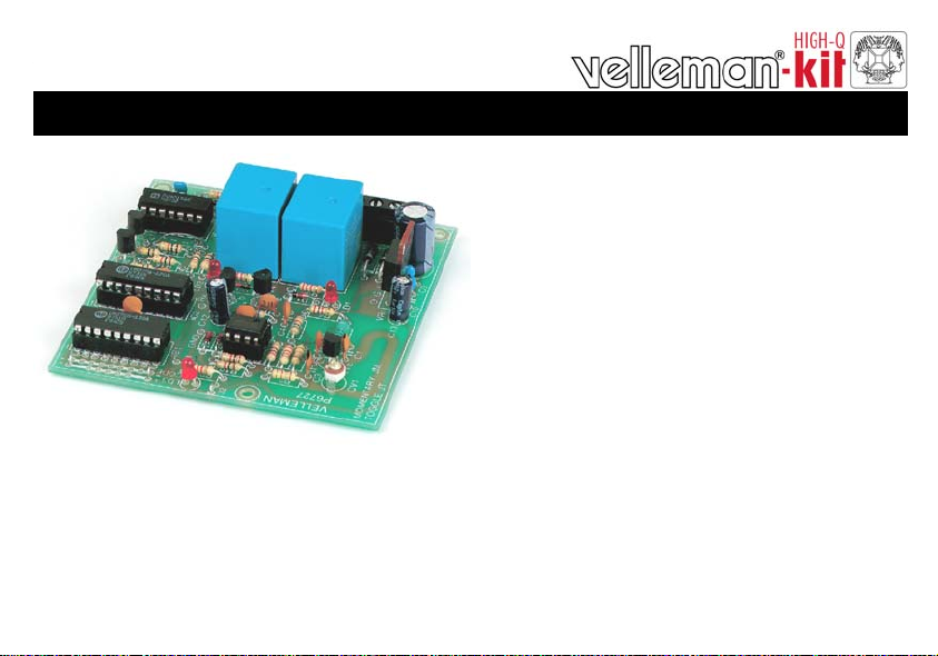
Total solder points: 224
Difficulty level: beginner 1 2 3 4 5 advanced
Two channel codelock receiver
K6727
,
s
m
e
t
s
y
s
m
r
a
l
O
n
e
p
o
t
r
o
p
r
a
c
.
.
c
t
e
,
s
t
s
i
d
e
t
a
r
e
p
a
m
o
r
f
.
.
e
c
n
a
g
n
i
t
h
g
i
l
o
f
m
o
c
a
m
r
a
,
e
l
b
a
t
r
ILLUSTRATED ASSEMBLY MANUAL H6727IP-2
1
Page 2
Features & Specifications
Features:
Easy to build: no coils to be made!
Works together with the K6706/K6706A two channel transmitter.
For operating garage door.
Operating outdoor or indoor lights.
Remote control of electrical door locks.
Remote control of pool lights or fountain…
Two power relays included.
Each output selectable for toggle or pulse contact.
It is possible to put two receivers in cascade at same location, for four channel output (in combination with
two transmitters).
Specifications:
Two code channels.
8.748 possible codes.
On / off LED indication for each channel.
Two 10A relay outputs.
Dimensions: 85 x 85mm
Power supply: 2x9VAC or 12 to 16VDC / 120mA
* modifications reserved.
NOT SUITED TO OPERATE MACHINES OR OTHER
!
EQUIPMENT THAT COULD CAUSE INJURIES .
2
Page 3
Assembly hints
0
.
0
0
0
1. Assembly (Skipping this can lead to troubles ! )
Ok, so we have your attention. These hints will help you to make this project successful. Read them carefully.
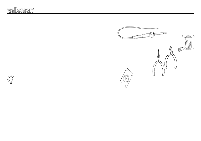
1.1 Make sure you have the right tools:
• A good quality soldering iron (25-40W) with a small tip.
• Wipe it often on a wet sponge o r c loth , to ke ep it c lean ; th en apply so lder to th e t ip, to g ive it a wet look. This is called ‘thinn ing’ an d w ill
protect the tip, an d enab les you t o make good conn ections. When so lder ro lls of f th e tip, it ne eds clean ing.
• Thin raisin-core solder. Do not use any flux or grease.
• A diagonal cutter to trim excess wires. To avoid in jury wh en cutting ex cess leads, ho ld the lead so th ey
cannot fly towards the eyes.
• Needle nose pliers, for bending leads, or to hold components in place.
• Small blade and Phillips screwdrivers. A basic range is fine.
For some projects, a basic multi-meter is required, or might be handy
1.2 Assembly Hints :
⇒ Make sure the skill level matches your experience, to avoid disappointments.
⇒ Follow the instructions carefully. Read and understand the entire step before you perform each operation.
⇒ Perform the assembly in the correct order as stated in this manual
⇒ Position all parts on the PCB (Printed Circuit Board) as shown on the drawings.
⇒ Values on the circuit diagram are subject to changes.
⇒ Values in this assembly guide are correct*
⇒ Use the check-boxes to mark your progress.
⇒ Please read the included information on safety and customer service
* Typographical inaccuracies excluded. Always look for poss ible last m inu te manu al updates, indicated as ‘NOTE ’ on a separate leaflet.
3
Page 4
Assembly hints
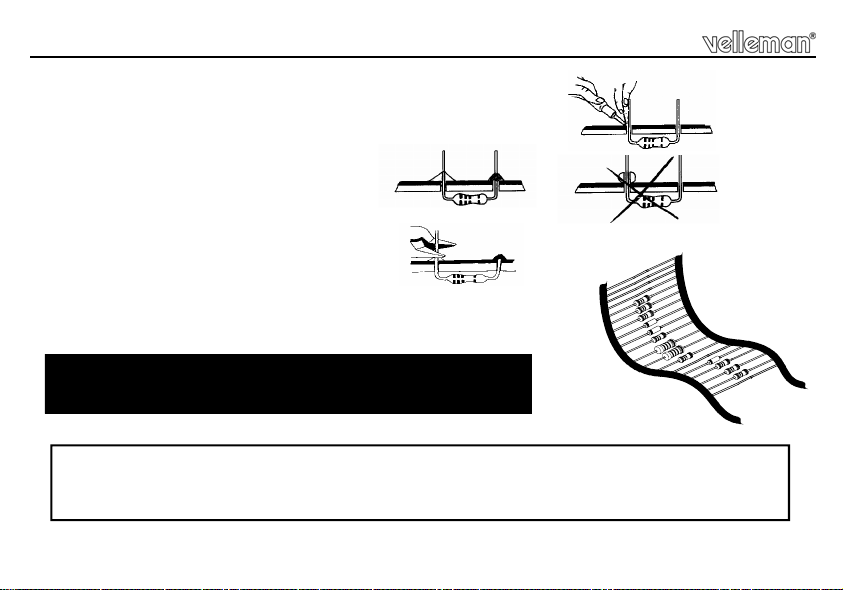
1.3 Soldering Hints :
1- Mount the component against the PCB surface and carefully solder the leads
2- Make sure the solder joints are cone-shaped and shiny
3- Trim excess leads as close as possible to the solder joint
REMOVE THEM FROM THE TAPE ONE AT A TIME !
AXIAL COMPONENTS ARE TAPED IN THE CORRECT
MOUNTING SEQUENCE !
Velleman hereby certifies that the device K6727 meets the essential requirements and all other relevant stipulations
For the complete conformity declaration check out :http://www.velleman.be/downloads/doC/CE_K6727.pdf
of directive 1999/5/EG an d 199 5/5 /EC .
4
Page 5
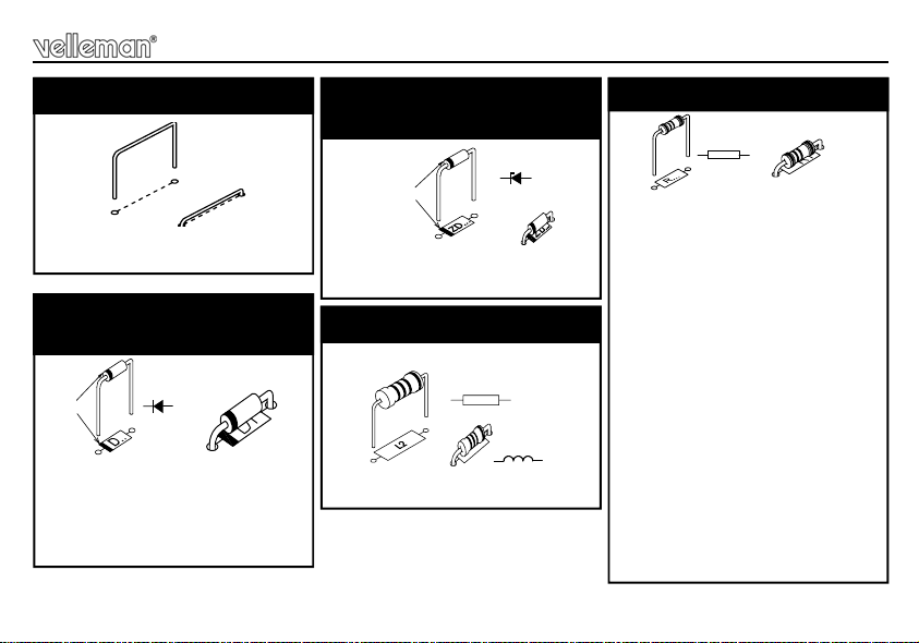
Construction
1. Jumper wires
J1
J2
2. Diodes.
Watch the polarity !
CATHODE
D1 : 1N4148
D2 : 1N4148
D3 : 1N4148
D4 : 1N4007
D5 : 1N4007
D...
3. Zener diodes
Watch the polarity !
CATHODE
ZD1 : 4V3
ZD2 : 4V7 (5V1)
4. SAW resonator.
L1 : 1µH (1-0-B)
ZD...
L2
L...
5. Resistors
R1 : 270 (2-7-1-B)
R2 : 18K (1-8-3-B)
R3 : 18K (1-8-3-B)
R4 : 33K (3-3-3-B)
R5 : 5K6 (5-6-2-B)
R6 : 2K7 (2-7-2-B)
R7 : 6K8 (6-8-2-B)
R8 : 6M8 (6-8-5-B)
R9 : 1K (1-0-2-B)
R10 : 1K (1-0-2-B)
R11 : 100K (1-0-4-B)
R12 : 100K (1-0-4-B)
R13 : 100K (1-0-4-B)
R14 : 100K (1-0-4-B)
R15 : 10K (1-0-3-B)
R16 : 10K (1-0-3-B)
R17 : 10K (1-0-3-B)
R18 : 10K (1-0-3-B)
R19 : 10K (1-0-3-B)
R20 : 2K2 (2-2-2-B)
R21 : 2K2 (2-2-2-B)
R22 : 2k2 (2-2-2-B)
R...
5
Page 6

Construction
LD1
CATHODE
6. IC sockets. (check the
position of the notch)
IC1 : 18p
IC2 : 18p
IC3 : 8p
IC4 : 14p
7. Capacitive trimmer
CV1 : 5pF
Set the tuning capacitor to
6
1
around the middle of its adjustment range.
IC...
CV...
C1 : 1p
C2 : 2p (2p2)
C3 : 22p
C4 : 82p
C5 : 330p (331)
C6 : 330p (331)
C7 : 330p (331)
C8 : 330p (331)
C9 : 100n (104)
C10 : 100n (104)
C11 : 100n (104)
8. Capacitors
10. LED’s. Watch the polarity!
C...
LD1
LD2
3mm Red
LD3
11. Screw connectors
First slide the connectors together
one by one.
SK1 : 3p
SK2 : 3p
SK3 : 3p
9. Transistors
T1 : BF199
T2 : BC557B
T3 : BC557B
T4 : BC547B
T5 : BC547B
Page 7

Construction
12. Capacitors.
Watch the polarity !
C12: 1µ
C13: 1µ
C14: 470µ
13. Voltage regula-
Mind the orientation !
VR1 : 7809
14. Relays
RY1 : VR15
RY2 : VR15
16. Sticker
Affix the supplied sticker to the
housing.
RY...
Velleman
433,92 MHz
SRFCE
C...
15. ICs. (check the position of
the notch)
VR...
IC1: UM3758-120A
IC2: UM3758-120A
IC3: RV4558 - LM258 - 2904
IC4: CD4013
1
PIN 1
IC...
7
Page 8

Personal code
17. Create your code
You can select your own code for a transmitter/receiver combination. There is a 9 row jumper island located directly
next to IC1 for setting the code. The code is set by connecting one or more code poin ts to a neighboring ‘+’ or ‘-‘ point
using the small jumpers. Code points may also be left unconnected (open): see figure.
: certain points cannot be connected to ‘+’
Note
8
a) No connection
b) Code connection to ‘-’ c) Example of a possible code
c) Code connection to ‘+’
Page 9

Operating mode
18. Operating mode
By using the jumpers JM1 or JT1, channel 1 of the receiver can be set up for two output possibilities:
1. Output channel 1 is o n w hile t he transmit ter i s pre ssed (MOM EN T), thi s is mo stly u sed for opera ting a do or lock,
garage door, etc.
JM1
2. Output channel 1 switches (on/off) every time the transmitter is pres sed (TOGGLE), this setting is mo stly used for
switching alarms in and out , for operati ng cen tral door lo cking syste ms, for sw itching a la mp on and off, e tc.
JT1
By using the jumpers JM2 or JT2, channel 2 from the receiver can be set up for two output possibilities:
1. Output channel 2 i s on w hile the t ransmitter is pr e ssed (MOM ENT).
JM2
2. Output channel 2 switches (on/off) every time the transmitter i s pressed (TOGGLE).
JT2
9
Page 10

Test & set-up
19. Test and set-up
IMPORTANT:
• For adj usting the receiver, a com pletely plastic tuning sc rewdriver (including plas tic blade) is needed. This is
supplied with the receiver.
• The t ransm itt er must be in its housing with the c over on, and fi tt ed with a ne w battery t ype V23GA or GP 23A.
Check the polarity which is shown in the housing.
• The receiver may not be in the vicinity of any metal objects.
• The transmitter and receiver must have the same code.
1) Use of the new K6706A transmitter:
• Set the tuning capacitor CV1 of the receiver to around the middle of its adjustment range (see fig. 7).
Check that the tuning LED of the receiver is not lit up, or is just on the verge of lighting up. If not, the tuning
capacitor will have to be adjus ted a little. Do not touch the circuit with your hand.
• Activate the transmitter and very carefully turn the tuning capacitor CV1 on the receiver until the tuning LED
lights up. If all is well, one of the relays should now switch, if of course the codes of the transmitter and receiver
are the same.
• For more precise tuning, get someone else to activate the transmitter from a few meters away and then finetune the receiver.
• Once the re ceiv er has be en set to a tra n smitt er, the n it will a lso be se t fo r oth er tran smi tte rs of the K670 6A ty pe .
2) Use of the old K6706 transmitter:
• Remove capacitor C1 from the transmitter.
• Set the tuning capacitor CV1 of the receiver to around the middle of its adjustment range (see fig. 7).
Check that the tuning LED of the receiver is not lit up, or is just on the verge of lighting up. If not, the tuning
capacitor will have to be adjusted a little. Do not touch the circuit with your hand.
10
Page 11

Test & set-up
• The transmitter must be in its housing with the cover off.
• Activate the transmitter (do not touch any other parts other than the push button) and then very carefully turn
the tuning capacitor CV on the transm itter unt il the tuning LED of the recei ver lights up. I f all is well, one of
the relays should now switch, if of course the codes of the transmitter and receiver are the same.
• For more precise tuning, activate the transmitter from a few meters away and then fine-tune the transmitter.
If the transmitter cannot be tuned to the receiver, then it might be that the tuning capacitor of the
receiver needs to be adjusted.
3) Use of a new K6706A transmitter together with an old K6706 transmitter:
• Do the receiver set-up and adjustment as in point 1 together with the new transmitter type K6706A.
• When using the old K6706 transmitter type, capacitor C1 of the transmitter must be removed.
• The transmitter must be in its housing with the cover off.
• Activate the transmitter (do not touch any other parts other than the push button) and then very carefully turn
the tuning capacitor CV on the transm itter unt il the tuning LED of the recei ver lights up. I f all is well, one of
the relays should now switch, if of course the codes of the transmitter and receiver are the same.
• For more precise tuning, activate the transmitter from a few meters away and then fine-tune the transmitter.
REMARK: When a new receiver K6727 is used in conjunction with a one channel receiver K6707, then on
the K6707 capacitor C1 must be a 1pF type.
11
Page 12

Connection
20. Connection
DC supply: AC supply:
CHANNEL 2
RELAY
OUTPUT
CHANNEL 1
RELAY
OUTPUT
K6727
NC2
COM2
NO2
NC1
COM1
NO1
GND
VB
VA
-
12...16 VDC
+
Other connections:
When using the relay output there is a choice between a normal ly closed contact (NC) or a normally open contact (NO). The common output is at COM.
12
CHANNEL 2
RELAY
OUTPUT
CHANNEL 1
RELAY
OUTPUT
K6727
NC2
COM2
NO2
NC1
COM1
NO1
GND
VB
VA
9VAC
9VAC
TRANSFO
L
MAINS
N
Page 13

Connection
21. Using 2 receivers at the same place
K6727
GND
J1
J2
Rx
K6727
GND
J1
J2
Rx
J1 & J2 CLOSED
ADJUST ONLY THIS RECEIVER
J1 & J2 OPEN
DO NOT ADJUST THIS RECEIVER
From one receiver, the jumpers J1 and J2 must be cut, this receiver must not be adjusted with the transmitter.
22. About the housing
The circuit can also be installed in a plastic housing (NOT A METAL BOX) e.g. WCAH2851.
Place the housing in a pl ace where there are few metal parts. It may be the case that after installation, the circuit
will have to be retuned. This is because of the influence of metal parts in the vicinity of the circuit.
13
Page 14

PCB
23. PCB layout.
14
Page 15

24. Diagram
V
Diagram
+
R1
270
R2
18K
82p
C4
L2
BF199
18KR36K8
330p
CV1
5p
1p
T1
C1
+V
L1
1uH
R6
2K7
4V3
C3
22p
R4
33K
R5
C8
5K6
330p
+V
D
9
12
FF1
10
JT1: TOGGLE
D
5
2
FF2
4
1
Q
JT2: TOG GLE
JM2: MOMENTARY
+V
Q
C11
100n
RST
Q
RST
T2
BC557B
CLK
R13
100K
R14
100K
11
R15
8Q13
10K
SET
JM1: MOMENTARY
+V
T3
BC557B
CLK
3
R16
10K
6
SET
C2
2p
R8
C12
R7
1u
C7
R9
1K
ZD1
R20
2K2
RED 3mm
LD1
R17
1N4 148
10K
D3
6M8
2
3
1/2 RV4 558
R1 0
1N4148
R18
10K
+V
5
8
A1
+V
1K
4V7
7
A2
1
4
R22
6
2K2
1/2 RV4558
LD3
RED 3mm
+V
100K
+V1
RY1
VR15M12I'C
BC5 47B
R11
C5
330p
NC
NO
COM1
T4
ZD2
D1
+V1
RED 3mm
R21
2K2
1N4148
LD2
D2
R19
10K
RY2
VR15M12I'C
T5
BC5 47B
NC
NO
COM2
J1
+V
Rx IN
OSC
IC1136
OUT
171011
14
VSS15MODE
IC1, IC 2 (UM 37 58-1 20A)
A1,A2 = IC3 (RV455 8)
FF1, FF 2 = IC4 ( CD 4013)
Rx
GND
VDD
A116 18
1
A2
2
A3
3
A4
4
A5
5
C6
A6
330p
7
A8
8
A9
9
A10
NC
A11
NC
A12
12
VA
GND
VB
+V
VDD
Rx IN
16 18
1
+V
2
3
100K
4
R12
OSC
5
IC2136
7
8
9
OUT
171011
12 NC
15
14
VSS
MODE
1N4 007
D4
D5
C14
100n
1N4 007
470u
+V
A1
A2
A3
A4
A5
A6
A7A7
A8
A9
A10
NC
A11
A12
+V1
J2
+VR
7809
+V
VR1
C9
C10
C13
1u
100n
15
Page 16

VELLEMAN Components NV
www.velleman-kit.com
Modifications and typographical errors reserved
© Velleman Components nv.
H6727IP - 2004 - ED2
16
Legen Heirweg 33
9890 Gavere
Belgium Europe
www.velleman.be
5 410329 291426
 Loading...