

Page 1

Total solder points: 187
Difficulty level: beginner 1 2 3 4 5 advanced
Code lock
K6400
d
l
o
e
s
o
h
t
f
o
d
i
r
d
e
G
s
a
f
ILLUSTRATED ASSEMBLY MANUAL H6400IP-2
d
e
n
o
i
h
s
y
e
k
Page 2

Features & Specifications
Features:
More than 3000 codes possible.
State indication by LED.
Pulse or switch output.
Nine digits of which 4 code digits.
Secured against polarity reversal.
Specifications:
Power supply : 9 to 15VDC or 8 to 12VAC.
Relay output : 5A / 220V.
Time limit for code determination : +/- 5sec.
Current consumption :
2
Output OFF : 0,3µ A
Output ON : 40mA
Page 3
Assembly hints
0
.
0
0
0
1. Assembly (Skipping this can lead to troubles ! )
Ok, so we have your attention. These hints will help you to make this project successful. Read them carefully.
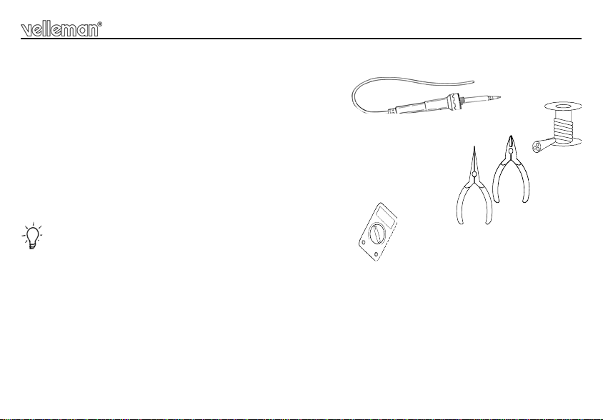
1.1 Make sure you have the right tools:
• A good quality soldering iron (25-40W) with a small tip.
• Wipe it often on a wet sponge or c loth , to kee p it c lean ; th en apply so lder to th e t ip, to g ive it a wet look. This is called ‘ thinning’ and will
protect the tip, an d enab les you t o make good conn ections. When so lder ro lls of f th e tip, it ne eds clean ing.
• Thin raisin-core solder. Do not use any flux or grease.
• A diagonal cutter to trim excess wires. To avoid in jury wh en cutting ex cess leads, ho ld the lead so th ey
cannot fly towards the eyes.
• Needle nose pliers, for bending leads, or to hold components in place.
• Small blade and Phillips screwdrivers. A basic range is fine.
For some projects, a basic multi-meter is required, or might be handy
1.2 Assembly Hints :
⇒ Make sure the skill level matches your experience, to avoid disappointments.
⇒ Follow the instructions carefully. Read and understand the entire step before you perform each operation.
⇒ Perform the assembly in the correct order as stated in this manual
⇒ Position all parts on the PCB (Printed Circuit Board) as shown on the drawings.
⇒ Values on the circuit diagram are subject to changes.
⇒ Values in this assembly guide are correct*
⇒ Use the check-boxes to mark your progress.
⇒ Please read the included information on safety and customer service
* Typographical inaccuracies excluded. Always look for poss ible last m inu te manu al updates, indicated as ‘NOTE’ on a separate leaflet.
3
Page 4
Assembly hints
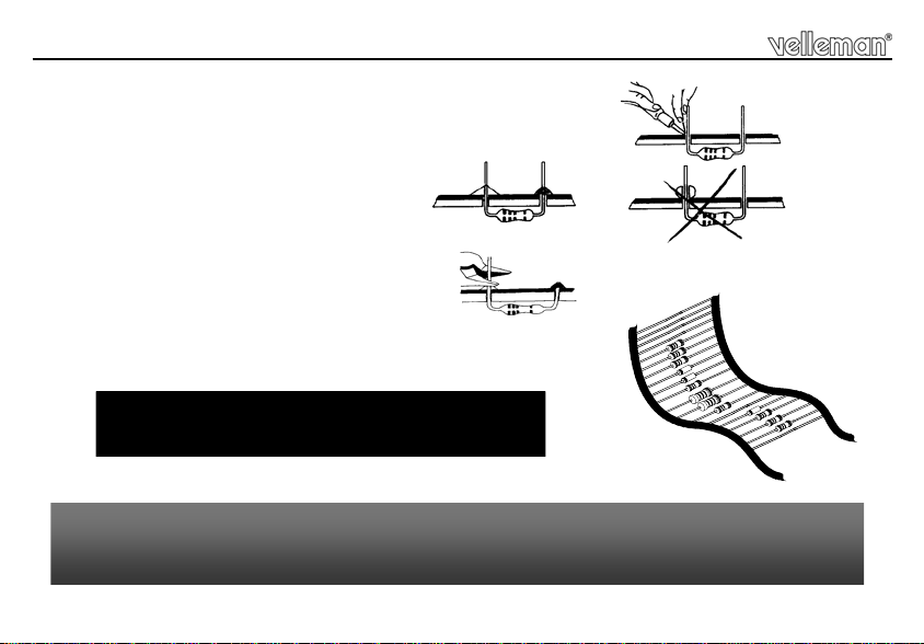
1.3 Soldering Hints :
1- Mount the component against the PCB surface and carefully solder the leads
2- Make sure the solder joints are cone-shaped and shiny
3- Trim excess leads as close as possible to the solder joint
REMOVE THEM FROM THE TAPE ONE AT A TIME !
AXIAL COMPONENTS ARE TAPED IN THE COR-
RECT MOUNTING SEQUENCE !
You will find the colour code for the resistances and the LEDs on our website:
http://www.velleman.be/common/service.aspx
4
Page 5

Assembly of the keyboard module : P6400S
LD1
CATHODE
CODE 1234
SW1
SW2
SW3
SW4
SW5
SW6
SW7
SW8
SW9SW9
SW8
SW7
SW6
SW5
SW4
SW3
SW2
SW1
P6400S
NABDC
Construction
1. Push button
SW1
SW2
SW3
SW4
SW5
2. Led’s. Watch the polarity!
LD1
SW6
SW7
SW8
SW9
3. Determining the code
The four code digits are determined by fitting wire jumpers, see figure 1.0.
Drawing 2 shows the connections for code 1234 as an example.
P6400S
CD BAN
SW1
SW2
SW3
SW4
SW5
SW6
SW7
SW8
SW9 SW9
Fig. 1
SW1
SW2
SW3
SW4
SW5
SW6
SW7
SW8
Fig. 2
Attention : the wire jumpers that build the code must be as close
to the pcb as possible, because otherwise they will touch the
aluminium front panel!
The code sequence is determined by connecting the lines A,
respectively B, C and D to the connecting t erminals (keys 1 through 9)
at the inside of the pcb, where line A is the fi rst code, B the second
code and so on. The unused keys (normally 5) are connected to line N.
5
Page 6

Construction
4. Preparation
Fit seven non insulated wires at the solder side of the pcb. These wires will be used later on for through
connection to the master module (see fig. 3.0).
Attention : the wires at the component side must be cut off as close to the pcb as possible.
P6400S
Fig. 3
6
Page 7

Assembly of the Master module : P6400B
Construction
1. Jumpers
J
on/off function of the key lock.
J1
Fit wire jumper J1 in case you intend to use the on/off function of the
key lock. If you don't fit this wire jumper, then, at the input of the code,
the code lock will only generate a pulse (in general this mode is used
with door locks).
"closed" contact or "open" contact .
NC or NO
Fit wire jumper NC if you intend to use the normally "closed" contact
of the relay, or wire jumper NO if you intend to use the normally "open"
contact of the relay.
ATTEN T ION : aft er the rela y has been fitted, t hese wire jum pers are
no longer accessible.
2. Diodes. Watch the polarity!
D1 : 1N4148
D2 : 1N4148
D3 : 1N4148
D4 : 1N4148
D5 : 1N4007
For D2 … D4 :
CATHODE
D...
The side with the mark comes
in the smallest hole marked C !
3. Resistors
R8 : 10 (1 - 0 - 0 - B)
R9 : 220 (2 - 2 - 1 - B)
R10 : 220 (2 - 2 - 1 - B)
R11 : 1K5 (1 - 5 - 2 - B)
R...
7
Page 8

RY...
C...
Construction
PIN 1
1
4. IC sockets, Watch the
position of the notch!
IC1 : 14p
5. Transistor
T1 : BC547B
T2 : BC547B
6. Resistors
R1 : 470K (4 - 7 - 4 - B)
R2 : 47K (4 - 7 - 3 - B)
R3 : 47K (4 - 7 - 3 - B)
R4 : 47K (4 - 7 - 3 - B)
R5 : 10K (1 - 0 - 3 - B)
R6 : 10K (1 - 0 - 3 - B)
R7 : 10K (1 - 0 - 3 - B)
8
7. Electrolytic capacitor.
Watch the polarity !
C1 : 10µ F
C2 : 470µ F
8. Screw connectors
10. IC. Check the position of
the notch!
IC1 : CD4066
J2 : 2p + 2p
9. Relay
R...
RY1 : VR15M121C
Page 9

Final assembly
Final Assembly
CHECK THE WHOLE MOUNTING ONCE
M2 BOLT
M2 NUT
MORE THOROUGHLY AND DON'T
FORGET THE CODE, BECAUSE AFTER
!
THE FOLLOWING ASSEMBLY IT
WON'T BE ACCESSIBLE ANY MORE.
10mm
SPACER
LOCK
WASHER
M2 NUT
P6400B
P6400S
Pass two 2mm bolts through the front panel and
fix th em usi ng a nut.
Then pass a lock washer over the bolts followed by
the keyboard module. Take care that the LED is in the front panel.
ALU FRONT
Fig. 4
Normally, neither the LED nor the push buttons may pass through the front panel. The push buttons
must be flush with the front side.
Pass a 10mm distance tube over the two bolts, followed by the master module. Also take care that the
through connections pass through the master module.
Now fix both modules using two nuts, where after you can solder the through connections (pay attention
to short-circuits).
9
Page 10

Test & usage
Test & usage
Connect a 9 to 15VDC or a 8 to 12VAC to the points V and GND. (V is the plus pole in the case of direct
current).
Put the front panel film next to the keyboard and enter the right code (in the case of a pulse out put this has
to be done within 5 seconds). If everything is going on well, now the relay should close and open again in
case pulse output mode has been selected. If however you have chosen for a constant switch position, then
you can cause the relay to open by entering a digit NOT belonging to the code digits.
Tip: should the opening tim e of the relay (in the case of the pulse output mode) be too short, fit a 22µ F
capacitor instead of C1 to change that time.
Building in
In case you use the key lock outside, it is advisable to mount it sunk, so that no water can soak in. For safety
you better first fix the code lock into the wall where aft er you stick the film to it, so that the fixation screws are
hidden "behind" the film.
Take care that, when sticking the film, the "LED WINDOW" corresponds with the hole in the aluminium.
10
Page 11

Schematic diagram & PCB
Schematic diagram (Control section)
GND
D5
V
1 2 3 4 5 6 7 8 9
C2
NOT USED
CODE A
CODE B
CODE C
CODE D
CODE ABCD
+V
R6
R9
R8
T2
R7
PCB
D1
+
SW3
SW6
SW9
N
B
A
D
C
NABDC
D5
VELLEMAN P6400B'1
C2
11
L
LD1
SW2
+V
R10
ES1
J1
C1
R1
ES2
D2
R2
ES3
+V
D3
R3
D4
R4
LD1
ES4
R11
R5
NC
+V
NO
RY1D1
COM
T1
SW1
VELLEMAN
SW4
P6400S'1
SW7
ABCD+
N
R7 R6
T2
1
R10
J1
C1
SW5
SW8
L
R9
R8
J
IC1
D3D2
CCC
R2R3R4
R1
OUT V GND
J2
RY1
R11
NC NO
D4
T1
R5
Page 12

VELLEMAN Components NV
www.velleman-kit.com
Modifications and typographical errors reserved
© Velleman Components nv.
H6400IP - 2004 - ED2 (rev.1.0)
Legen Heirweg 33
9890 Gavere
Belgium Europe
www.velleman.be
5 410329 291327
 Loading...