

Page 1

Total solder points: 186
Difficulty level:
Beginner 1o 2þ 3o 4o 5o Advanced
K4305
2 x 10 LED STEREO VU METER
• For instant visualization of audio signal levels.
• Easy hook up to a LINE level ( LOW input) signal source.
• For use with mixing panels, amplifiers, CD players, radio’s, ...
• A special input (HIGH INPUT) is provided, which allows direct con-
nection to a SPEAKER* output .
• DOT or BAR display mode selectable to suit your application.
• Attractive display window supplied, which can be used both horizontal
as vertical.
• If wanted, the unit can be calibrated by means of a trim potentiometer.
*NOT SUITED FOR CONNECTION TO HIGH POWER CAR STEREO
SYSTEM
Specifications:
• 2 X 10 LED’s
• BAR OR DOT MODE
• INDICATION RANGE: 0dB = 0.775mVrms.
-20dB, -10dB, -7dB, -5dB, -3dB, -1dB, 0dB, +1dB, +2dB, +3dB
• FREQUENCY RANGE: 20Hz tot 30KHz
• LOW INPUT FOR 0dB: 150mV to 6Vrms (47K)
• HIGH INPUT FOR 0dB: 1.5V to 60Vrms (470K).
• POWER SUPPLY: 10 to 15VDC / 250mA max.
• PCB DIMENSIONS 2X: 68X37mm
modifications reserved
PARTLIST H4305P-ED1
Page 2
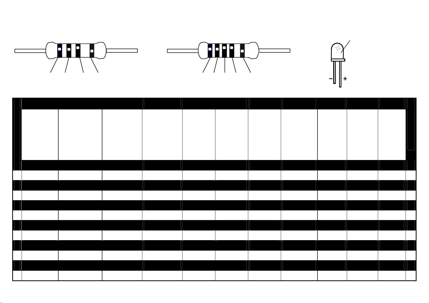
5%
1
2
3
4
5
6
7
8
9
A
B
1%
COLOR= 2… 5
4K7= ( 4 - 7 - 2 - B )
4K7= ( 4 - 7 - 0 - 1 - 1 )
I P E SF S DK N D GB F NL
CODICE
C
COLORE
O
D
E
CODIGO
DE
CORES
CODIGO
DE
COLORES
VÄRI
KOODI
FÄRG
SCHEMA
FARVE
KODE
FARGE
KODE
FARB
KODE
COLOUR
CODE
CODIFICATION
DES
COU-
LEURS
KLEUR
KODE
0
Nero Preto Negro Musta Svart Sort Sort Schwarz Black Noir Zwart
Marrone Castanho Marrón Ruskea Brun Brun Brun Braun Brown Brun Bruin
Rosso Encarnado Rojo Punainen Röd Rød Rød Rot Red Rouge Rood
Aranciato Laranja Naranjado Oranssi Orange Orange Orange Orange Orange Orange Oranje
Giallo Amarelo Amarillo Keltainen Gul Gul Gul Gelb Yellow Jaune Geel
Verde Verde Verde Vihreä Grön Grøn Grønn Grün Green Vert Groen
C
O
D
E
0
1
2
3
4
5
Blu Azul Azul Sininen Blå Blå Blå Blau Blue Blue Blauw
Viola Violeta Morado Purppura Lila Violet Violet Violet Purple Violet Paars
Grigio Cinzento Gris Harmaa Grå Grå Grå Grau Grey Gris Grijs
Bianco Branco Blanco Valkoinen Vit Hvid Hvidt Weiss White Blanc Wit
Argento Prateado Plata Hopea Silver Sølv Sølv Silber Silver Argent Zilver
Oro Dourado Oro Kulta Guld Guld Guldl Gold Gold Or Goud
6
7
8
9
A
B
Page 3

__________________________________________________________________________________________________________________________________________________________
ASSEMBLY STEPS
Required tools to assemble the kit:
A small soldering iron of max. 40W.
Thin (1mm) solder, do not use any flux.
A small cutter to trim the excess wires.
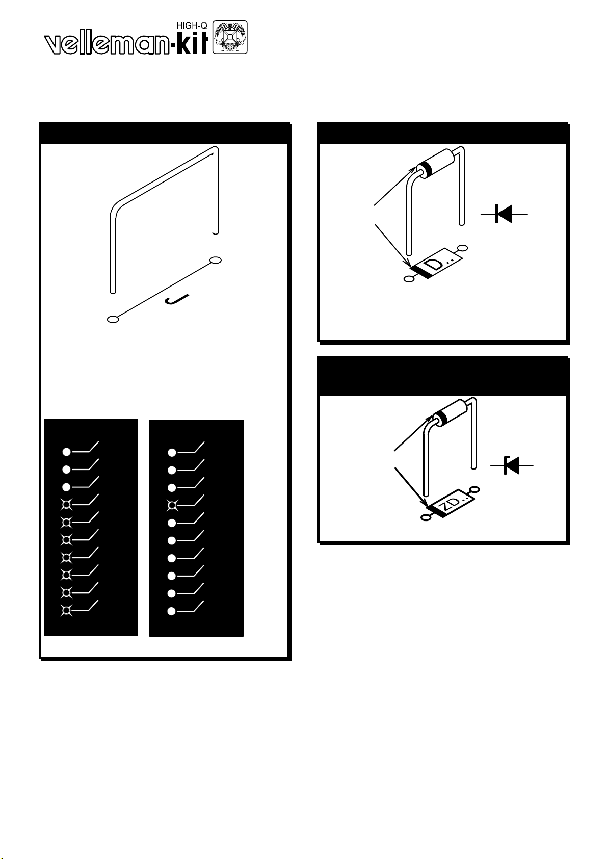
1.
Mount the components against the
PCB surface and
carefully solder the
leads.
2.
Obtain cone- shaped,
shiny soldered joints
by heating the component leads sufficiently.
3.
This solder joint
results in a bad
connection.
4.
Trim the excess
wires up to the
level of the solder
• Careless assembly will certainly lead to troubles.
• Insert the part, oriented correctly, into its correct holes on the PCB.
• Mount the components in the correct order as stated in this manual.
• The component values in the diagram are for reference only. The val-
ues in this partlist are correct and must be followed.
• Use the boxes q to tick off your progress.
F Before starting to build, also read the general guidelines
3
Page 4
_______________________________________________________________________________________________________________________________________________________
Assembly
Mount all components onto the PC boards (mount the two boards)
1. JUMPERS
q J1
q J2, mount for BAR mode, do
not mount for DOT mode.
BAR DOT
2. DIODES (Check the polarity)
D...
CATHODE
q D1: 1N4148
q D2: 1N4148
q D3: 1N4000… 1N4007
3. ZENER DIODES
(Check the polarity)
+3
+2
+1
0dB
-1
-3
-5
-7
-10
-20
+3
+2
+1
0dB
-1
-3
-5
-7
-10
-20
ZD...
CATHODE
q ZD1: 6,2V (6V2)
4
Page 5
__________________________________________________________________________________________________________________________________________________________
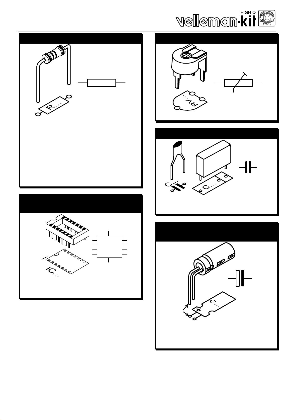
4. ¼W RESISTORS
R...
q R1: 47K (4-7-3-B)
q R2: 47K (4-7-3-B)
q R3: 330 (3-3-1-B)
q R4: 10K (1-0-3-B)
q R5: 10K (1-0-3-B)
q R6: 2K2 (2-2-2-B)
q R7: 470K (4-7-4-B)
5. IC SOCKETS
(Check the position of the notch)
6. RESISTOR TRIMMERS
RV...
q RV1: 220K (250K)
7. CAPACITORS
C...
q C1: 220nF (0.22µF, 224)
q C2: 220nF (0.22µF, 224)
1
q IC1: 8P
q IC2: 18P
IC...
8. ELECTROLYTIC CAPACITOR
(Check the polarity)
C...
+
q C3: 47µF
q C4: 47µF
q C5: 47µF
5
Page 6

_______________________________________________________________________________________________________________________________________________________
9. 1W RESISTORS
q R8: 68 (6-8-0-B)
R...
2mm
6
Page 7

__________________________________________________________________________________________________________________________________________________________
10. MOUNT THE LEDs, BEND THE LEADS CAREFULLY
(Check the polarity)
LED
SOLDER
SIDE
PCB
COLOR = 2...5
q LD1: green (5)
q LD2: green (5)
q LD3: green (5)
q LD4: green (5)
q LD5: green (5)
q LD6: green (5)
q LD7: green (5)
q LD8: yellow (4)
q LD9: yellow (4)
q LD10: red (2)
LD...
CATHODE
7
Page 8

_______________________________________________________________________________________________________________________________________________________
11. Insert the IC’s in the socket (Check the position of the notch)
1
PIN 1
IC...
q IC1: 741
q IC2: LM3916
Mount the units in a suitable housing or on a suitable panel:
12. Mounting possibility:
A. Make or search for suitable bracket:
8
Page 9

__________________________________________________________________________________________________________________________________________________________
B. Make the holes in the housing or panel and mount the bracket:
7
15
7
4.5
Ø3.5
52
FRONTPANEL
BRACKET
60
10mm M3 COUNTERSUNK-HEAD BOLT
2...3mm FRONTPANEL
LOCK WASHER
M3 NUT
BRACKET
LOCK WASHER
M3 NUT
9
Page 10

_______________________________________________________________________________________________________________________________________________________
C. Mount the PCB’s with spacers onto the bracket:
M3 NUT
LOCK WASHER
FRONTPANEL
15mm SPACER
15mm SPACER
2...3mm FRONTPANEL
SOLDER
SIDE
M3 NUT
LOCK WASHER
PCB
15mm SPACER
PCB
15mm SPACER
BRACKET
BRACKET
40mm M3 BOLT
40mm M3 BOLT
10
Page 11

__________________________________________________________________________________________________________________________________________________________
Connect the unit to a suitable signal, this can be line level (LOW input) :
13. Connecting to a line level output (tuner, preamp, cd player… )
and connecting a power supply from 10 to 15VDC / 250mA max..
HIGH IN
LOW IN
LEFT
+
P4304
L
TAPE
OUT
R
FROM AUDIO AMPLIFIER
MAINS
MAINS
1N4007
12V/250mA
12V/250mA
1N4007
12V/250mA
1000uF/25V
HIGH IN
LOW IN
+
+
1000uF/25V
RIGHT
+
+
10...15VDC
POWER
SUPPLY
P4304
Connect the unit to a suitable supply voltage between 10VDC and
15VDC, this can also be a standard DC adapter. You can also build
your own power supply, see diagram. Use a 2x12V transformer, two
rectifier diodes and a electrolytic capacitor or use a single 12V transformer with a bridge rectifier and a electrolytic capacitor.
11
Page 12

_______________________________________________________________________________________________________________________________________________________
Connect the unit to a speaker output (HIGH input):
14. Connecting to a speaker level output and connecting a power
supply from 10 to 15VDC / 250mA max..
SPEAKER LEFT
INPUT (0)
SPEAKER RIGHT
-
+
+
-
FROM POWER AMPLIFIER
MAINS
MAINS
1N4007
12V/250mA
12V/250mA
1N4007
12V/250mA
1000uF/25V
+
+
1000uF/25V
HIGH IN
LOW IN
HIGH IN
LOW IN
LEFT
+
RIGHT
+
+
10...15VDC
POWER
SUPPLY
P4304
P4304
Connect the unit to a suitable supply voltage between 10VDC and
15VDC, this can also be a standard DC adapter. You can also build
your own power supply, see diagram. Use a 2x12V transformer, two
rectifier diodes and a electrolytic capacitor or use a single 12V transformer with a bridge rectifier and a electrolytic capacitor.
12
Page 13

__________________________________________________________________________________________________________________________________________________________
Connect the unit to a car radio:
15. Connecting to a speaker output from a regular car radio.
LEFT SPEAKER
RIGHT SPEAKER
+12V ANTENNE POWER OUT
CAR RADIO
L+
L-
R+
R-
HIGH IN
LOW IN
HIGH IN
LOW IN
LEFT
+
RIGHT
+
P4304
P4304
The 12VDC car battery power or car radio antenna output can be used
to supply the VU meter.
REMARK: Do not connect the unit to a high power car booster or car
stereo, this equipment uses isolated ground connection. The connection
to this kind of amplifier can cause permanent damage to the amplifier or
car radio!
• Adjust the units sensitivity according to your preference by means of
the trim potentiometer RV1
13
Page 14

_______________________________________________________________________________________________________________________________________________________
14
 Loading...