

Page 1
Total solder points: 33
Difficulty level: beginner 1 2 3 4 5 advanc ed
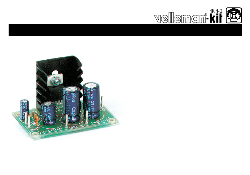
7W MONO AMPLIFIER
K4001
e
s
o
p
r
u
p
i
t
l
u
m
l
u
f
r
e
w
o
p
t
u
b
l
l
a
m
S
Specifications
Music output power : 7W/4ohm
RMS output power : 3.5W/4ohm or 2W/8ohm
Power supply : 8-18VDC/0.5A
Dimensions : 55x35mm (2.2” x 1.4”)
ILLUSTRATED ASSEMBLY MANUAL H4001IP-1
m
a
.
r
e
i
f
i
l
p
Page 2

VELLEMAN NV
Legen Heirweg 33
9890 Gavere
Belgium Europe
www.velleman.be
www.velleman-kit.com
Page 3

Features & Specifications
Features:
This small am plifier is constructed around the TDA2003 IC, capable of deli vering 4Wrms at 4ohms. The IC is completely
thermally and short-circuit protected. A conventional direct current can be connected as suppl y.
Specifications :
Music output power : 7W /4ohm
RMS output power : 3.5W /4ohm or 2W/8ohm
T otal harmonic distortion : 0.05% (1W/1KHz)
Frequency response : 20Hz-20KHz (-3dB)
Input sensitivity : 40mV/15 0Kohm
Signal/noise ratio : 86dB (A weighted)
Power supply : 8-18VDC/0.5A
Dimensions : 55x35mm (2.2” x 1.4”)
3
Page 4
Assembly hints
0
.
0
0
0
1. Assembly (Skipping this can lead to troubles ! )
Ok, so we have your attention. These hints will help you to make this project successful. Read them carefully.
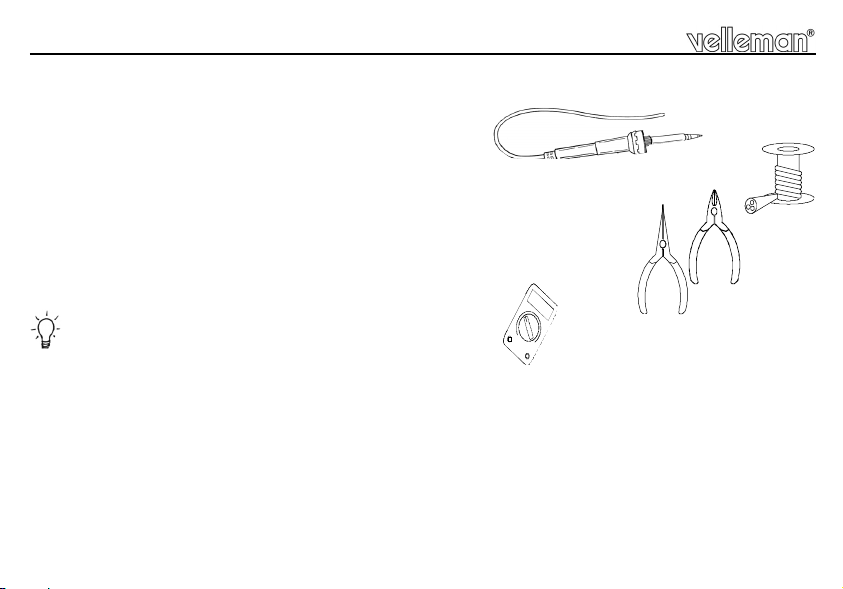
1.1 Make sure you have the right tools:
• A good quality soldering iron (25-40W) with a small tip.
• Wipe it often on a wet sponge or cloth, to keep it clean; then apply solder to the tip, to give it a wet look. This is called ‘thinning’ and will
protect the tip, and enables you to make good connections. When solder rolls off the tip, it needs cleaning.
• Thin raisin-core solder. Do not use any flux or grease.
• A diagonal cutter to t rim exc ess wires. To avoid injury when cutting excess l eads, hold the le ad so they
cannot fly towards the eyes.
• Needle nose pliers, for bending leads, or to hold components in place.
• Small blade and Phillips screwdrivers. A basic range is fine.
For some projects, a basic multi-meter is required, or might be handy
1.2 Assembly Hints :
⇒ Make sure the skill level matches your experience, to avoid disappointments.
⇒ Follow the instructions carefully. Read and understand the entire step before you perform each operation.
⇒ Perform the assembly in the correct order as stated in this manual
⇒ Position all parts on the PCB (Printed Circuit Board) as shown on the drawings.
⇒ Values on the circuit diagram are subject to changes.
⇒ Values in this assembly guide are correct*
⇒ Use the check-boxes to mark your progress.
⇒ Please read the included information on safety and customer service
* Typograp hical inaccuracies excluded. Always look f or possible last minute manua l upda tes, indicated as ‘ NOTE’ on a s eparate l eaflet.
4
Page 5

1.3 Soldering Hints :
1- Mount the component against the PCB surface and carefully solder the leads
2- Make sure the solder joints are cone-shaped and shiny
3- Trim excess leads as close as possible to the solder joint
DO NOT BLINDLY FOLLOW THE ORDER OF THE
COMPONENTS ONTO THE TAPE. ALWAYS CHECK
THEIR VALUE ON THE PARTS LIST!
REMOVE THEM FROM THE TAPE ONE AT A TIME !
Assembly hints
5
Page 6

Construction
1. Resistors.
R1 : 470 (4 - 7 - 1 - B)
R2 : 4,7 (4 - 7 - B - B)
R3 : 100 (1 - 0 - 1 - B)
2. Metal film resistor.
R4 : 1 (1 - 0 - B - B - 9)
3. Capacitors.
R...
R...
C1 : 8n2 (822)
C2 : 100nF (104)
C3 : 100nF (104)
6
4. PCB tabs
IN
GND
LS
GND
+V
GND
5. Electrolytic Capacitors.
Watch the polarity !
C4 : 10µF
C5 : 470µF
C6 : 1000µF
C7 : 1000µF
6. IC.
IC1 : TDA2003!
C...
Page 7

Supply c onnection
7. Supply connection
Figure 1 is an example of a suitable mains supply f or this circuit. Naturally, you can also use batteries to
power the circuit.
FUSEH OLDER
MAINS
STRAIN RE LIEF
FUSE 1A T
POWE R SWITCH 240V 3A
TRANSFORMER
12V AC 6VA
RECTIFIER BRIDGE
1.5A 50V
+-
ELECTROLYTIC CAPACITOR 2200µF 25 V
Fig. 1.0
7
Page 8

Volume c ontrol
8. Volume control
Adjust the volume by connecting a 47K logarithmic potentiometer as indic ated in figure 2.0.
TO AMPLIFIER
POTE NTIOME TER
Signal IN
GND
FROM SOURCE
SHIELDED CABLE
47K OHM LOG
GND
SIGNAL (+)
Fig. 2.0
8
Page 9

Connection example
9. Connection example
Figure 3.0 is an example of a connection diagram of a 4 or 8 ohm speaker that is connected to the pins LS
and GND. The input signal should be c onnect ed with the IN and GND pins.
FROM AUDIO SOURCE
4/8 OHM SPEAKER
-
+
47K LOG POTENTIOMETER
+
-
8..18VDC / 0.5A
+
-
Fig. 3.0
9
Page 10

PCB
10. PCB layout.
10
Page 11

11. Diagram
Diagram
11
Page 12

Modifications and typographical errors reserved - © Velleman nv. H4001IP - 2004 - ED1_rev.1
5 410329 289003
 Loading...