

Page 1
Total solder points: 166+116
Difficulty level:
beginner 1o 2o 3o 4þ 5oadvanced
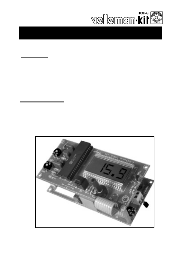
Thermostat with LCD-display
Features:
þ Wide measuring and regulating range: -50 to +150°C (-60 to +300°).
þ Adjustable hysteresis: 0,2°C (0,4°F) to 10°C (18°F).
þ Resolution of the display: 0,1°C or 1°F.
þ Can be set for degrees Celsius or Fahrenheit.
þ Connecting capability for economy switch.
K2649
Specifications :
• Power supply and transformer included.
• Mains voltage: 220/240V (110 for USA and Canada).
• Relay output: 240V, 3A max.
• Dimensions: 123.5x62x65 mm.
ILLUSTRATED ASSEMBLY MANUAL H2649IP-1
Page 2
2
VELLEMAN Components NV
Legen Heirweg 33
9890 Gavere
Belgium Europe
www.velleman.be
www.velleman-kit.com
Page 3
0.000
Assembly hints
1. Assembly (Skipping this can lead to troubles ! )
Ok, so we have your attention. These hints will help you to make this project successful. Read them carefully.
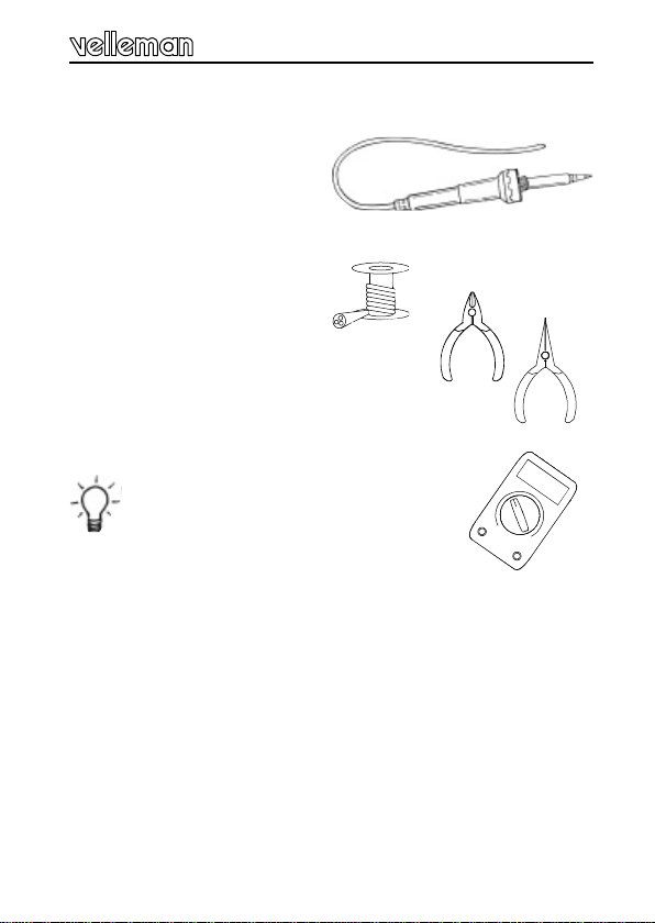
1.1 Make sure you have the right tools:
• A good quality soldering iron (2540W) with a small tip.
• Wipe it often on a wet sponge or cloth, to keep it clean; then apply solder to the
tip, to give it a wet look. This is called ‘thinning’ and will protect the tip, and enables you to make good connections. When solder rolls off the tip,
it needs cleaning.
• Thin raisin-core solder. Do not use
any flux or grease.
• A diagonal cutter to trim excess wires. To avoid injury
when cutting excess leads, hold the lead so they
cannot fly towards the eyes.
• Needle nose pliers, for bending leads, or to hold components in
place.
• Small blade and Phillips screwdrivers. A basic range is fine.
For some projects, a basic multi-meter is required, or
might be handy
1.2 Assembly Hints :
⇒ Make sure the skill level matches your experience, to avoid disappointments.
⇒ Follow the instructions carefully. Read and understand the entire step before you
perform each operation.
⇒ Perform the assembly in the correct order as stated in this manual
⇒ Position all parts on the PCB (Printed Circuit Board) as shown on the drawings.
⇒ Values on the circuit diagram are subject to changes.
⇒ Values in this assembly guide are correct*
⇒ Use the check-boxes to mark your progress.
⇒ Please read the included information on safety and customer service
* Typographical inaccuracies excluded. Always look for possible last minute manual
updates, indicated as ‘NOTE’ on a separate leaflet.
3
Page 4
Assembly hints
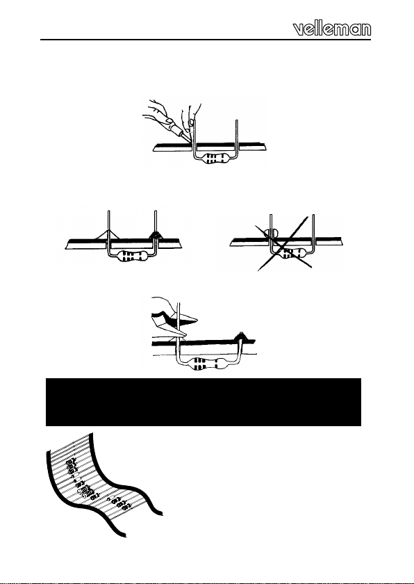
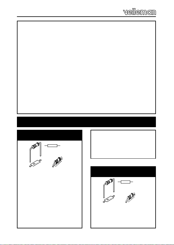
1.3 Soldering Hints :
Mount the component against the PCB surface and carefully solder the
leads
Make sure the solder joints are cone-shaped and shiny
Trim excess leads as close as possible to the solder joint
AXIAL COMPONENTS ARE TAPED IN THE CORRECT
MOUNTING SEQUENCE !
REMOVE THEM FROM THE TAPE
ONE AT A TIME !
4
Page 5
5%
4K7= ( 4 - 7 - 2 - B )
1%
4K7= ( 4 - 7 - 0 - 1 - 1 )
COLOR= 2… 5
C O D
E
KODE
COLOR= 2...5
KLEUR
CODIFI-
CATION
DES COU-
CODE
COLOUR
FARB
KODE
KODE
FARGE-
KODE
FARVE-
FÄRG
SCHEMA
VÄRI
KOODI
ORES
CODIGO
DE COL-
LEURS
I P E SF S DK N D GB F NL
CODIGO
DE CORES
CODICE
COLORE
C O D E
0 Nero Preto Negro Musta Svart Sort Sort Schwarz Black Noir Zwart 0
1 Marrone Castanho Marrón Ruskea Brun Brun Brun Braun Brown Brun Bruin 1
2 Rosso Encarnado Rojo Punainen Röd Rød Rød Rot Red Rouge Rood 2
3 Aranciato Laranja Naranjado Oranssi Orange Orange Orange Orange Orange Orange Oranje 3
4 Giallo Amarelo Amarillo Keltainen Gul Gul Gul Gelb Yellow Jaune Geel 4
5 Verde Verde Verde Vihreä Grön Grøn Grønn Grün Green Vert Groen 5
6 Blu Azul Azul Sininen Blå Blå Blå Blau Blue Bleu Blauw 6
7 Viola Violeta Morado Purppura Lila Violet Violet Violet Purple Violet Paars 7
8 Grigio Cinzento Gris Harmaa Grå Grå Grå Grau Grey Gris Grijs 8
9 Bianco Branco Blanco Valkoinen Vit Hvid Hvidt Weiss White Blanc Wit 9
A Argento Prateado Plata Hopea Silver Sølv Sølv Silber Silver Argent Zilver A
B Oro Dourado Oro Kulta Guld Guld Guldl Gold Gold Or Goud B
Page 6
Construction
R...
R...
The very precise digital display of both the set and actual
temperature makes this thermostat very easy to use.
Also very useful is the connecting capability for an
'economy switch': when the contact is closed then the set
temperature is decreased by a number of degrees.
No measuring apparatus is needed for adjustments.
Thanks to the wide setting range of both the hysteresis
and the desired temperature, this kit can also be used for
a lot more applications than only regulating room temperature.
Assembling instructions :
The whole consist out of two parts : the regulating and
power supply module P2649V and the display module
P2649D
A. Power supply mode
1. Resistors
q R1 : 560 (5-6-1-B)
q R3 : 100K (1-0-4-B)
q R4 : 100K (1-0-4-B)
q R6 : 100K (1-0-4-B)
q R15 : 220K (2-2-4-B)
q R16 : 220K (2-2-4-B)
q R17 : 560K (5-6-4-B)
q R18 : 560K (5-6-4-B)
q R26 : 820 (8-2-1-B)
q R27 : 1K (1-0-2-B)
q R28 : 10K (1-0-3-B)
q R29 : 82 (8-2-1-B)
q R34 : 6K8 (6-8-2-B)
q R35 : 5M6 (5-6-5-B)
2. Metalfilm resistors
q R20 : 10K (1-0-0-2)
q R21 : 10K (1-0-0-2)
q R22 : 47K (4-7-0-2)
q R23 : 47K (4-7-0-2)
6
Page 7
Construction
C...
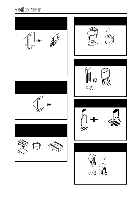
3. Diodes
Watch the polarity !
CATHODE
D...
q D1: 1N4007
q D2: 1N4007
q D3: 1N4007
q D4: 1N4007
q D5: 1N4148
4. Zenerdiode
Watch the polarity !
CATHODE
ZD...
q ZD1: 8V2
5. IC socket, watch the
position of the notch!
q IC2 : 14p
6. Potentiometers
R4
q RV4 : 10K
7. Transistor
q T1: BC557B
8. Ceramic Capacitor
q C3: 100nF (104)
9. Potentiometers
RV...
q RV5 : 4M7
7
Page 8
Construction
C...
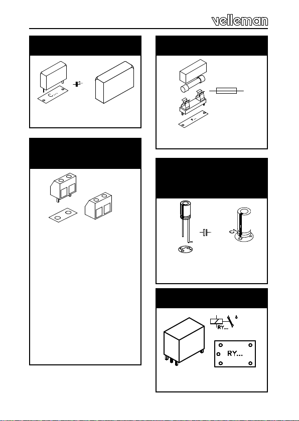
10. Capacitor
q C10 : 1µF/63V
11. Terminal blocks
connectors
q J1 : Mains.
q J4 : “ES” Economy
switch.
q J2 :
— For heaters use the
contacts : ‘C’ & ‘NO’.
— For coolers use the
contacts : ‘C’ & ‘NC’.
G The connection side of
the connectors must point
to the PCB-opening!
12. Fuseholder & Fuse
F...
q F1 : 100mA (slow)
13. Electrolytic
Capacitors.
Watch the polarity !
q C2 : 100µF
q C1 : 1000µF
14. Relay
q RY1 : VR15M121C
8
Page 9
Construction
15. Transformer
220V 12V
17. Flatcable
TRANSFORMER
q TRAFO1 : 12V - 0,1A
q J3 : FC8 “9 wire”
16. Flat cable. watch
the position of the
notch!
q IC2 : LM324
18. Choosing hysteresis
— Small hysteresis
If you desire a small hysteresis (adjustable from 0,2 to 1°
C or from 0,4 to 4°F), then fit for R24 and R25 a 180K
metal film resistor (brown, grey, black, orange).
— Larger hysteresis
If you prefer a larger hysteresis (between 1 and 10°C or
2 and 20°F, for instance for water heaters and such-like),
then fit a wire link for R24 an R25.
9
Page 10

Construction
R...
B. Display module
1. Jumpers
q J (4x)
Choose temperature
display :
q JC for Temperature in
degrees Celsius.
q JF for degrees Fahren-
heit.
2. Resistors
q R2 : 91K (9-1-0-2)
q R5 : 100K (1-0-4-B)
q R9 : 1K8 (1-8-2-B)
Mount for R10 :
q 390 (3-9-1-B)
for Degrees Celsius.
q 330 (3-3-1-B)
OR
for Degrees Fahrenheit.
10
q R11 : 120K (1-2-4-B)
q R12 : 18K (1-8-3-B)
Mount for R13 :
q 1M (1-0-5-B)
for Degrees Celsius.
OR
q 150K (1-5-4-B)
for Degrees Fahrenheit
- - - - -
q R19 : 4M7 (4-7-5-B)
q R30 : 47K (4-7-3-B)
q R31 : 10K (1-0-3-B)
q R33 : 22K (2-2-3-B)
GFor degrees Celsius,
the following resistors
must be fitted too :
q R7 : 100K (1-0-4-B)
q R8 : 100K (1-0-4-B)
q R14 : 150K (1-5-4-B)
Page 11

Construction
3. IC socket, watch the
position of the notch
4. Potentiometers
R4
q RV1 : 4K7 (5K2)
q RV2 : 100
q RV3 : 10K
q IC1 : 40p
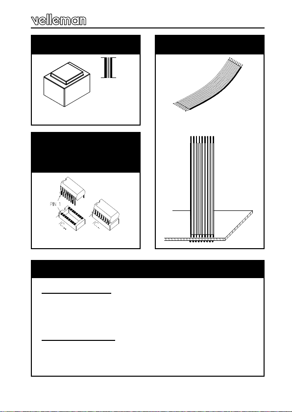
5. LCD display
LCD
FIG. 1.0
G Pay attention to the position : the upper surface
must be at 8mm (0,3 inch) above the pcb surface (see
drawing 1.0).
You may put some pieces of paper between the LCD and
the pcb, to help you holding the display on the right
height.
q First solder only the pins at the four corners.
q Verify the height, and correct if necessary.
q Then solder the remaining pins.
GBe very careful, for this part is not cheap!
11
Page 12

Construction
C...
6. Ceramic Capacitors
q C4 : 100nF (104)
q C6 : 100pF (101)
7. Capacitor
q C5 : 10nF / 250V
q C7 : 100nF / 250V
q C8 : 220nF / 100V
q C9 : 470nF / 63V
8. Transistor
q T2 : BC557B
Attention : For degrees
Fahrenheit this transistor
should not be fitted!
12
9. LED
Watch the polarity !
LD1
CATHODE
q LD1: 5mm Red
10. Pushbutton
q S1 : S500
Page 13

Construction
11. Flat cable
P2649D
!
P2649V
Attention : The connecting order (whit regard to the pcb-
edge) must be the same as on the power supply module
(see fig. 2.0).
FIG. 2.0
12. IC, watch the position of the notch!
q IC1 : ICL7106
13
Page 14

Sensor
13. Sensor
Calibration is performed by alternately adjusting the meter
at the freezing respectively boiling-point of water. Therefore the sensor first has to be prepared.
G DON'T shorten the connection wires of the sensor,
unless you are not going to fit it directly onto the pcb in the
future.
q Solder two isolated wires (75 cm or 30“) to the sensor
(see fig. 3.0)
Make use of a cable of the desired length (max 10m, and
preferably screened to avoid interferences) if you are not
going to fit the sensor onto the pcb in the future.
Make the connections waterproof with heat-shrinkable
tubing :
q Cut off a piece of shrinking tube with a lenght equal to
5cm.
q Slide the shrinking tube over the wires and over the
sensor (Fig. 4.0).
FIG. 3.0
14
Page 15

Sensor
q Heat the shrinking tube using a hair dryer or , better
still, using a paint stripper.
FIG. 4.0
G Take care that everything is well covered.
Connect the whole to the place marked with 'R32 SENSOR'. The connection order is unimportant, unless with
screened cable: the screen then comes on the side
marked with 'SENSOR'. Connect a mains cable to the
screw connector J1-MAINS.
15
Page 16

Adjustment
14. Adjustment
During assembly you already made your choice for degrees Celsius or degrees Fahrenheit version.
The adjusting method is the same for both, only the values on the display are different. The figures for Fahrenheit are mentioned within brackets.
The first adjustment is done at the freezing-point.
— Fill a beaker with ice cubes and plunge the sensor into
the melting-water (Fig. 5.0). As long as not all the ice
is molten, the temperature of the melting-water is kept at
0°C (32°F), and after a few minutes the sensor will be at
0°C too.
Fig. 5.0
— Then adjust with RV2 until the display reads 00.0 (32°F).
— After zero-adjustment, the sensitivity of the meter has to
be adjusted.
— Plunge the sensor into boiling water, but see to it that
the sensor does not come too close to the bottom or wall
of the kettle.
— After a few minutes, the sensor temperature has risen to
100°C (212°F).
— Then adjust with RV3 until the display reads 100.0
(212°F).
— Now let it cool down for about half an hour, and do the
complete adjustment over again once more.
G Remark : when the sensor has to be replaced for any
reason, then you have to readjust completely!
16
Page 17

Use
15. Use
The set temperature is displayed when you push the button
S1.
You can change it by gradually turning potentiometer RV1
until the display shows the desired temperature.
With the standard values for R2 and R33 (91K resp. 22K),
the adjusting range is about 5 to 30°C (40 to 85°F).
You can change this range by using other values for R2
and R33 :
-50°C (-60°F) to 0°C (32°F) 51K 7K5
+50°C (120°F) to 100°C (212°F) 33K 12K
+100°C (212°F) to 150°C (300°F) 33K 16K
Range R2 R3
G You can also experiment yourself in order to obtain an
optimum adjusting range for your application.
— Solder a 1M trimmer parallel to both R2 and R33 (see fig.
6.0).
— Adjust both trimmers so that you obtain the optimum range.
— Afterwards replace the trimmers by normal resistors which
approximate the set value as close as possible.
17
Page 18

Use
R2
R33
1M
1M
FIG. 6.0
You can lower the set temperature by a number of degrees
(preset with RV5), e.g. by night or during your absence, by
connecting a switch or a relay contact (e.g. a timer such like
K2603 or K1682) at the place marked with 'E.S.' (Economy
Switch).
The hysteresis is the difference between the temperatures at which the output is switched on resp. switched off.
Depending on the application, a smaller or larger hysteresis may be desired: to regulate the room temperature for
instance, a small hysteresis is desirable. On the contrary,
this makes no sense with water-heaters, so, in this case,
you should select a larger hysteresis.
You can adjust the hysteresis with RV4.
The adjusting range is about 0,2 to 2°C (0,4 to 4°F) when
R24 and R25 are 180K resistors, and 1 to 10°C (2 to 18°F)
when you fitted wire links.
18
Page 19

Use
The setting of the hysteresis does not depend on the set
temperature. Do not set the minimum hysteresis right
from the beginning: in this case the regulation is most
precise, however it could happen that the heating gets
switched on and off much too fast and too often (e.g.
when the thermostat is located near the radiator).
This is not too healthy for the heating installation and/or
relay, and too much energy is consumed. Therefore start
with RV4 in the middle position, and then search the ideal
position for your application.
Suppressing inductive loads :
Should the operation of the thermostat get disturbed by
the switching of inductive loads (even if the switched
power is not so high), then this is due to the sparks produced in the relay. In most cases this can be remedied by
putting a VDR (e.g. VDR300) over the contacts. Moreover
a series connection of a 100 ohm resistor with a 47 or
100nF/400V capacitor can be placed in parallel with the
VDR in order to further reduce the sparks (see Fig. 7.0).
LOAD
100 ohm / 0,5W
VDR
(VDR300)
100nF/400V
MAINS
FIG. 7.0
19
Page 20

Mounting
16. Mounting
* Spacers & screws are not included.
FIG. 8.0
FLAT CABLE
SENSOR
The rectangular opening in the power supply module is
used as a passage for the wiring to the mains input, the
relay output and the E.S. (Economy Switch), see fig. 9.0
Mains
Economy switch
FIG. 9.0
Relay output
20
Page 21

Mounting
The display module can be mounted above the power
supply module using spacers (See fig. 10).
FIG. 10
This thermostat exactly fits into the box type B2649.
In case you use this box, you can fit the sensor onto the
pcb in such a way that it passes through the opening in the
side of the bottom. In this way, the sensor reacts more
quickly and accurately upon the room temperature, and it
doesn't get influenced by the heat-dissipation of the transformer and such-like.
21
Page 22

Mounting
In case of panel-mounting, you may use a some what
longer flat cable, so you can simply mount the pcb's with
their solder sides towards each other, and the connections are easily accessible.
You also could use screw connectors for the sensor
connection. Wherever and for whatever application the
thermostat may be used, always take into account that
the mounting of the sensor determines the quality of the
regulation: the quicker it reacts upon the changing temperature, the better.
In case of liquids, this is not such a problem: you can
attach the sensor on the outside of the metal pipe or boiler
(you could use a little bit of heat-conducting paste), or make
the sensor waterproof and plunge it into the liquid.
Air however is a much worse heat-conductor, so that the
body of the sensor does not heat up/cool down that
quickly. This can be improved by circulating the air
around the sensor.
Especially in large rooms, which are heated by means of
hot air, it can be interesting to place the sensor in the
(cold) air circulation, for instance nearby the air inlet of
the convector.
The intake air (which has the actual room temperature)
then makes the sensor warm up quickly as the room temperature increases.
22
Page 23

PCB
&
DIAGRAM
23
Page 24

PCB
17. PCB layout. (Display module)
24
Page 25

Power module
PCB
25
Page 26

Schematic diagram
18. Schematic diagram.
COM
NO
NC
26
JC
D1...D4
TRAF01
F1
JF
+V1
1
16
40392832301127
38
37
36
35
34
LCD1
33
12
8
7
6
5
4
R1
C1
220VAC
+V2
+V2
2
20
2524232221
3
19
9
18
31
17
29
16
10
15
13
14
26
13
25
12
24
11
15
10
14
9
17
8
23
7
22
6
21
31/2 DIGIT LCD MODULE
+V1
5
20
4
19
3
18
2
26
1
+V2
C4
+V2
R11
R9
+V2
C2
C3
R34
R2
4
11
+V2
A1 ... A4 = IC2
RV3
RV2
RV1
T14
T2
T1
+V1
R8
LD1
RY1
R29
D5
+V1
R27
R7
R28
C8
R30
C9
IC1
C7
NC
C6
R5
R19
R13 C5
R12
R20 R17 R24
R31
R3 R17
R10
R6
A4
+
RV4
+V2
A3
+
-
R21 R23 R25 R26
S1
R18
A1
-
A2
+
-
+
R4
R15
R16
R32
RV5
R33
R35
E.S.
Page 27

27
Page 28

VELLEMAN Components NV
Legen Heirweg 33
9890 Gavere
Belgium Europe
www.velleman.be
www.velleman-kit.com
Modifications and typographical errors reserved
© Velleman Components nv.
H2649IP - 2002 - ED1
 Loading...