

Page 1

HAMGSM133
GSM BIDIRECTIONAL REMOTE CONTROL 2IN/2OUT
DUPLEX AFSTANDSBEDIENINGMODULE 2 IN/2 OUT
MODULE DE TÉLÉCOMMANDE BIDIRECTIONNELLE GSM 2 IN/2 OUT
MÓDULO DE MANDO A DISTANCIA BIDIRECCIONAL MÓVIL 2 I/2 O
DUPLEX FERNBEDIENUNGSMODUL 2 IN/2 OUT
USER MANUAL 6
GEBRUIKERSHANDLEIDING 16
NOTICE D’EMPLOI 26
MANUAL DEL USUARIO 36
BEDIENUNGSANLEITUNG 46
Page 2

A
1
H
u
n
3
m
t
–
n
n
AMGSM1
3
H
MGSM
33/USB
* not incl
(not i
ded – niet
cluded, nie
eegelev.
meegelev.,
pas livré –
non fourni,
nicht mitgel
nicht mitge
iefert – no i
liefert, no in
cl.
cl.)
V.
02 – 15/05/2
012
2
©Vellema
nv
Page 3
HAMGSM133
A B
C D
V. 02 – 15/05/2012 3 ©Velleman nv
Page 4
HAMGSM133
E F
G H
V. 02 – 15/05/2012 4 ©Velleman nv
Page 5
HAMGSM133
I J
K
V. 02 – 15/05/2012 5 ©Velleman nv
Page 6

.
oIm
e
.3.
.
p
o
n
n
m
s
t
e
eand
e
A
n
y
a
e
a
n
g
e
c
c
e
o
S
n
n
e
E
t
h
n
t
a
n
e
n
u
e
s
a
c
m
w
t
a
d
h
o
c
y
e
n
s
o
d
M
1
n
t
r
t
c
a
o
m
m
u
e
i
u
w
u
y
e
o
i
n
a
S
t H
t
o
.
e
r
n
s
t
e
a
s
t
e
n
u
y
r
e
z
3
N
t
c
t
o
e
o
c
u
t
r
e
.
e
y
t
e
f
b
v
r
o
r
o
p
n
e
a
e
a
i
o
a
o
b
d
b
u
z
n
r
e
r
s
m
w
t
o
t
m
l
a
d
n
l
s
AMGSM1
3
1
Intr
T
all reside
portant e
Th
ank you for
th
device wa
2
Safe
• The H
• Disco
• Strictl
• Read
This
har
shou
distri
If in
Ke
Th
Ke
duction
ts of the
vironmen
symbol on t
the enviro
ld be taken
butor or to
doubt, co
choosing V
damaged i
y Instr
p the devic
re are no u
/or spare p
p this devi
MGSM133
nect the po
comply wi
nd underst
uropean U
al informa
e device o
ment. Do n
o a speciali
local recy
tact your l
lleman! Ple
transit, d
ctions
away fro
er-servicea
rts.
e away fro
ust be mo
er from th
h the techn
nd the full
USE
ion
ion about
the packag
ot dispose
zed compan
ling service
ocal waste
se read th
n't install o
children a
ble parts in
rain, mois
nted into a
device wh
cal specific
ser manual
R MA
his produ
e indicates
f the unit (
y for recycli
Respect th
disposal a
manual th
use it and
d unauthori
ide the dev
ure, splashi
suitable ho
n handling.
tions at all
before ope
UAL
t
hat disposa
r batteries)
ng. This de
local envi
uthorities.
roughly bef
ontact you
sed users.
ice. Refer t
ng and drip
sing (not i
imes.
ating the d
l of the devi
as unsorte
ice should
onmental r
re bringing
dealer.
an authori
ing liquids.
cluded) bef
vice.
ce after its l
municipal
e returned
les.
this device
ed dealer f
ore use.
ifecycle cou
aste; it
o your
into service
r service
d
. If
Gen
• Famili
• All mo
• Only u
• Dama
• Nor V
4
Prer
Fo
llowing list
• power
• valid
• housi
O
tional:
• USB i
to the
warra
dealer
indire
produ
For th
ral Gui
Keep t
Protect
rise yourse
difications o
device is n
se the devi
ty.
e caused b
will not acc
lleman nor
t) – of any
t.
quisite
f items is n
supply (9V
IM card
g
terface HA
HAMGSM
elines
is device a
this device
lf with the f
f the device
t covered b
e for its int
disregard
pt respons
its dealers c
ature (fina
t included
c to max. 3
GSM133/U
33/USB,
ay from du
from shock
nctions of
are forbidd
the warra
nded purpo
f certain g
bility for an
an be held
cial, physic
nd must b
2Vdc stabili
B
he driver so
st and extr
and abuse
he device b
n for safet
ty.
se. Using th
idelines in
ensuing d
esponsible
al…) arising
purchased
ed)
ftware can
me temper
Avoid brut
fore actuall
reasons. D
e device in
his manual
fects or pr
or any dam
from the p
separately
e found on
tures.
force whe
y using it.
amage caus
n unautho
s not cover
blems.
ge (extrao
ssession, u
y the user:
www.velle
operating
ed by user
ised way wi
d by the w
dinary, inci
e or failure
an.be
he device.
odification
l void the
rranty and
ental or
of this
the
V.
02 – 15/05/2
012
6
©Vellema
nv
Page 7

HAMGSM133
5. Overview
Refer to the illustrations on page 2 of this manual.
1 power supply 3 SIM card (not included)
2 USB interface (optional) * 4 antenna connector
* HAMGSM133/USB, not included
O1 output 1 I1 input 1
O2 output 2 I2 input 2
LD1 relay 1 active
LD2 relay 2 active
LD3 input 1 active (logical condition reached)
LD4 input 2 active (logical condition reached)
LD5 GSM network connection status
U1 transmit LED U3 mini USB connector
U2 receive LED
6. Installation
• When applicable install the USB interface HAMGSM133/USB [2] (not included). The mini USB connector
must be on top.
• Insert a valid SIM card [3]. Make sure the PIN code of the SIM card is disabled. Use a normal mobile
phone for this.
• Connect the antenna to the antenna connector [4].
• Make all necessary connections (I1, I2, O1, O2). Only connect a SELV (Safety Extra Low Voltage) load
to the outputs. Tension applied to the contacts of each relay must not exceed 60Vdc; switching current
on the relays must not exceed 10A (short peak). The maximum tension applied to the digital inputs is
32Vdc.
• Connect the power supply [1] (not included). Use a stabilized current-limited power supply (not
included) providing 9~32Vdc and at least 500mA current (able to deal with absorption peaks of 1A).
Note that the centre tip is positive.
• Close the housing (not included).
7. Introduction
• The HAMGSM133 is a bidirectional remote control module capable of remotely controlling two relays
(in monostable or bistable mode) through the use of special SMS commands sent from any mobile
phone.
• Memory for up to 8 telephone numbers to which SMS and/or ringtones can be sent when input status
changes (master list).
• It is also possible to use the HAMGSM133 as a gate control receiver controlled by up to 200 entered
phone numbers (gate control list).
• To facilitate programming, it is possible to connect a USB interface module and manage the device via
PC through downloadable software. This module must be purchased separately; order code
HAMGSM133/USB.
8. Configuration
There are 3 ways to set up the device:
• through call (only at start-up)
• through SMS
• through USB (USB interface required, not included).
8.1 Through call (only at start-up)
When the device is supplied with power, “LD5” will immediately flash at 1 Hz frequency. The HAMGSM133 will
try to connect to the GSM network. When connected, “LD5” will briefly flash every 2 seconds. After the system
initialization (which may take several seconds), the device alternately illuminates yellow LEDs “LD3” and “LD4”
to indicate the “configuration call” on hold mode for 3 minutes. If during this time the unit receives a call, it
stores the caller’s number (to which reply SMS will be sent) in the first memory location and LD3 and LD4 turn
off.
V. 02 – 15/05/2012 7 ©Velleman nv
Page 8

HAMGSM133
Note: the caller ID of the used mobile phone must not be hidden (callers’ phone number must be visible when
calling another mobile phone).
At the end of the hold mode the yellow LEDs are switched off and the device waits for a configuration SMS.
With the same phone used to make the first setup call, it is also possible to switch the relay status.
8.2 Through SMS
This mode takes full advantage of the device with operations as output switch, output status query, inclusion of
additional phone numbers to activate the relay, inclusion of numbers for door opening function, reception of
reply messages; change output signals timing and, in general, set the HAMGSM133 with all parameters via
simple SMS. A full reset to restore the default settings can also be made via SMS. See below for the syntax for
all available commands.
8.3 SMS syntax
• Commands and settings can be sent from any mobile phone as long as the message includes the
password.
• For some commands a password is not required when the message was sent from a telephone number
which is stored in the HAMGSM133. However, some commands that change critical information always
require a password.
• The HAMGSM133 replies with a confirmation or information SMS.
• Multiple commands can be combined in 1 SMS by placing a comma in between.
• Note: commands never contain spaces.
Refer to overview of all configuration SMS commands below.
Change password
Password required
Command PWDxxxxx;pwd
xxxxx = new password (5 digits)
pwd = current password (default = 12345)
Example PWD54321;12345
Store numbers
Password required for overwrite or from unknown phone
Command NUMx+YYnnnnnnnnnn;pwd
YY = country code
x = position of the number in the list (1~8)
nnnnnnnnnn = phone number (max. 19 digits)
pwd = current password (default = 12345)
Example NUM7+324851234567;12345
Result Number +324851234567 is stored on location 7 in the master list.
Remove numbers
Password Required
Command NUMx;pwd
x = position of the number in the list (1~8)
pwd = current password (default = 12345)
Example NUM5;12345
Result The number on location 5 is removed from the master list.
List stored numbers
Password required
Command NUM?;pwd
pwd = current password (default = 12345)
Example NUM?;12345
Result Show the master list.
V. 02 – 15/05/2012 8 ©Velleman nv
Page 9

HAMGSM133
Factory reset
Password required
Command RES;pwd
pwd = current password (default = 12345)
Example RES;12345
Enable SMS reception
Password required
Command SMSxxxxxxxx:ON;pwd
xxxxxxxx = position of the number in the list (1~8)
pwd = current password (default = 12345)
Example SMS15:ON;12345
Result Phone numbers on position 1 and 5 will receive an SMS when input status
changes. Other numbers are not affected. By default all eight phone numbers
receive an SMS.
Disable SMS reception
Password required
Command SMSxxxxxxxx:OFF;pwd
xxxxxxxx = position of the number in the list (1~8)
pwd = current password (default = 12345)
Example SMS27:OFF;12345
Result Phone numbers on position 2 and 7 will NOT receive an SMS when input
status changes. Other numbers are not affected.
Enable ringtone reception
Password required
Command VOCxxxxxxxx:ON;pwd
xxxxxxxx = position of the number in the list (1~8)
pwd = current password (default = 12345)
Example VOC15:ON;12345
Result Phone numbers on position 1 and 5 will receive a ringtone when input status
changes. Other numbers are not affected. By default all eight phone numbers
receive ringtones.
Disable ringtone reception
Password required
Command VOCxxxxxxxx:OFF;pwd
xxxxxxxx = position of the number in the list (1~8)
pwd = current password (default = 12345)
Example VOC36:OFF;12345
Result Phone numbers on position 3 and 6 will NOT receive a ringtone when input
status changes. Other numbers are not affected.
Set logic alarm level to HIGH (alarm when input under tension)
Password
Command LIVx:A
x = 1 (input 1) or 2 (input 2)
Example LIV2:A
Result Set alarm level on input 2 to high, alarm is activated when input 2 is under
tension. Default both inputs are set to level HIGH.
V. 02 – 15/05/2012 9 ©Velleman nv
Page 10

HAMGSM133
Set logic alarm level to LOW (alarm when input tensionless)
Password
Command LIVx:B
x = 1 (input 1) or 2 (input 2)
Example LIV1:B
Result Set alarm level on input 1 to low, alarm is activated when input 1 loses
tension.
Set logic alarm level to switching (alarm when input tension changes)
Password
Command LIVx:V
x = 1 (input 1) or 2 (input 2)
Example LIV1:V
Result When tension changes on input 1, e.g. from low to high, the alarm is
activated.
Request logic alarm level
Password
Command LIV?
Example LIV?
Result Get a list of logic alarm levels on both inputs.
Inhibition time input 1
Password
Command INI1:mm
mm = time in minutes (00~59)
Example INI1:02
Result After alarm activation, the device will not check the alarm level on input 1 for
2 minutes (inhibition time). Default = 5 minutes
Inhibition time input 2
Password
Command INI2:mm
mm = time in minutes (00~59)
Example INI2:15
Result After alarm activation, the device will not check the alarm level on input 2 for
15 minutes (inhibition time). Default = 5 minutes
Request inhibition times
Password
Command INI?
Example INI?
Result Get a list of the inhibition time on both inputs.
Reset inhibition time input 1
Password
Command TIZ1x
x = 0 (no reset) or 1 (reset)
Example TIZ11
Result Inhibition time reset on input 1 when input 1 is idle. Default = no reset
V. 02 – 15/05/2012 10 ©Velleman nv
Page 11

HAMGSM133
Reset inhibition time input 2
Password
Command TIZ2x
x = 0 (no reset) or 1 (reset)
Example TIZ20
Result Inhibition time does not reset on input 2 when input 2 is idle. Default = no
reset
Request status of reset function
Password
Command INI?
Example INI?
Result Receive the status of the reset function on the inputs.
Alarm condition time-out input 1
Password
Command OSS1:ss
ss = time in seconds (00~59)
Example OSS:08
Result The alarm on input 1 must remain for 8 seconds before the alarm is passed
on. Default = 1 second
Alarm condition time-out input 2
Password
Command OSS2:ss
ss = time in seconds (00~59)
Example OSS2:15
Result The alarm on input 2 must remain for 15 seconds before the alarm is passed
on. Default = 1 second
Request alarm condition time-outs
Command OSS?
Example OSS?
Result Get a list of the alarm condition time-outs on both inputs.
Alarm SMS content when input 1 tension is high
Password
Command TIN1A:xxxxxxxx
xxxxxxxx = message (max. 100 characters, all capitals)
Example TIN1A: TENSION ON INPUT 1
Result When tension is detected on input 1, an SMS is sent out with text “TENSION
ON INPUT 1”. Default: ALARM! INPUT 1 HIGH
Note: a semi colon (;) is not allowed inside the message
Alarm SMS content when input 1 tension is low
Password
Command TIN1B:xxxxxxxx
xxxxxxxx = message (max. 100 characters, all capitals)
Example TIN1B1: NO TENSION ON INPUT 1
Result When no tension is detected on input 1, an SMS is sent out with text “NO
TENSION ON INPUT 1”. Default: ALARM! INPUT 1 LOW
Note: a semi colon (;) is not allowed inside the message
V. 02 – 15/05/2012 11 ©Velleman nv
Page 12

HAMGSM133
Alarm SMS content when input 2 tension is high
Password
Command TIN2A:xxxxxxxx
xxxxxxxx = message (max. 100 characters, all capitals)
Example TIN2A: TENSION ON INPUT 2
Result When tension is detected on input 1, an SMS is sent out with text “TENSION
ON INPUT 2”. Default: ALARM! INPUT 2 HIGH
Note: a semi colon (;) is not allowed inside the message
Alarm SMS content when input 2 tension is low
Password
Command TIN2B:xxxxxxxx
xxxxxxxx = message (max. 100 characters, all capitals)
Example TIN2B: NO TENSION ON INPUT 2
Result When no tension is detected on input 1, an SMS is sent out with text “NO
TENSION ON INPUT 2”. Default: ALARM! INPUT 2 LOW
Note: a semi colon (;) is not allowed inside the message
Activate a relay output
Password
Command OUTx:ON
x = 1 (output 1) or 2 (output 2)
Example OUT1:ON
Result Activate output relay 1
Deactivate a relay output
Password
Command OUTx:OFF
x = 1 (output 1) or 2 (output 2)
Example OUT2:OFF
Result Deactivate output relay 2
Invert the condition of a relay for a certain time
Password
Command OUTx:ss
x = 1 (output 1) or 2 (output 2)
ss = time in seconds (00~59)
Example OUT1:10
Result Deactivate (when already active) or activate (when deactivated) output relay
1 for the next 10 seconds.
Request condition of outputs
Password
Command STA?
Example STA?
Result Get an overview of the condition of the output relays.
Store and restore relay status after power cut
Password
Command RIPx
x = 0 (disabled) or 1 (enabled)
Example RIP1
Result Relay statuses are automatically stored when a power outage occurs and
restored when power is restored. Default: 1 (enabled)
V. 02 – 15/05/2012 12 ©Velleman nv
Page 13

HAMGSM133
Request current setting of relay status backup
Password
Command RIP?
Example RIP?
Result Get an overview of the current setting for the output relay backup.
Start-up SMS content
Password
Command TSU:xxxxxxxx
xxxxxxxx = message (max. 100 characters, all capitals)
Example TSU: SYSTEM START-UP
Result When enabled (see AVVx command), this message is send to phone number
on the first position in the list. Default: SYSTEM STARTUP
Note: a semi colon (;) is not allowed inside the message
Activate start-up SMS
Password
Command AVVx
x = 0 (disabled) or 1 (enabled)
Example AVV1
Result Enable sending an SMS to the phone number on the first position in the list
when the device is started or restarted. Default: 0 (disabled)
Gate control activation (relay 1)
Password
Command TAC:ss
ss = time in seconds (00~59)
Example TAC:12
Result When receiving a call from any of the 200 gate control numbers or 8
numbers in the master list, the relay will remain activated for 12 seconds.
Default: 3 seconds
Note: When setting the time to 00, the relay operates in bi-stable mode;
relay 1 will switch status every time the device receives a call.
Store gate control phone numbers (max. 200)
Password required
Command MAC+YYnnnnnnnnnn;pwd
YY= country code
nnnnnnnnnn = phone number (max. 19 digits)
pwd = current password (default = 12345)
Example MAC+324851234567;12345
Note: There are no specific locations for gate control phone numbers.
Delete gate control phone numbers
Password required
Command DAC+YYnnnnnnnnnn;pwd
YY= country code
nnnnnnnnnn = phone number to delete
pwd = current password (default = 12345)
Example DAC+324851234567;12345
Disable reply SMS
Password
Command RISP (commands)
Commands: series of commands separated by commas (,)
Example RISP, OUT1:ON, DAC, INI1:10
V. 02 – 15/05/2012 13 ©Velleman nv
Page 14

HAMGSM133
8.4 With a PC and USB interface
Refer to the illustrations on pages 3, 4 and 5 of this manual.
This mode allows setting up HAMGSM133 with a computer and software (English) you can download from the
Velleman website connected through a USB interface (not included, order ID HAMGSM133/USB).
Install the software on the PC before connecting the HAMGSM133 to the USB port.
With the software, you can manage all programming and settings as well as change the list of enabled users.
This speeds up the initial setup and saves on the cost of SMS.
After starting the software, make sure the communication speed is set to 9600 Baud (8, N, 1).
Refer to the full user manual for more information on the installation and use of the software.
Note: While the device is connected to a PC, managing via SMS is disabled.
Installing the software
• Go to www.velleman.be
• On the product page, click Software and then Save.
• Run the setup file and follow the instructions on the screen.
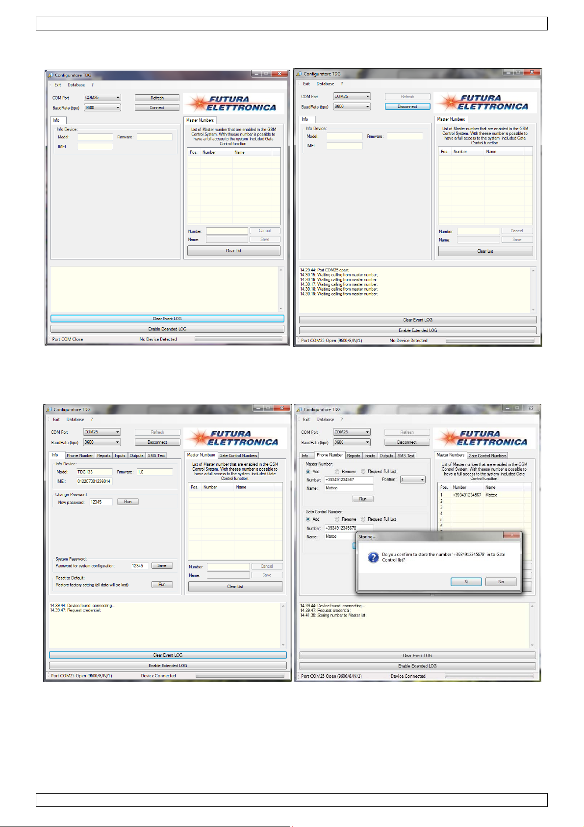
• When installation is completed, start the software. The configuration window [A] appears.
• Connect the HAMGSM133 to the USB port of the computer using an appropriate cable (not included).
• Select the desired COM port (top left).
• Click on ‘Connect’ (top centre) to activate the connection. When data is already present inside the
module, it will be shown.
• If no master number is available in the module, the “Waiting for Call for Master Number Storage”
message appears in the log window [B] (at the bottom of the screen). Make a call to the HAMGSM133
before proceeding. A confirmation message is shown in the log window.
• The configuration window now shows a number of tabs.
• In the “Info” tab [C] you can find model number, firmware version and IMEI (International Mobile
Equipment Identity). It is also possible to change the password in this tab.
To be able to change the settings, enter the current password into the “system password” field and click
“Save”.
If the device does not react to commands from the computer, make sure the password stored in the PC
is the same as the one specified in the management program.
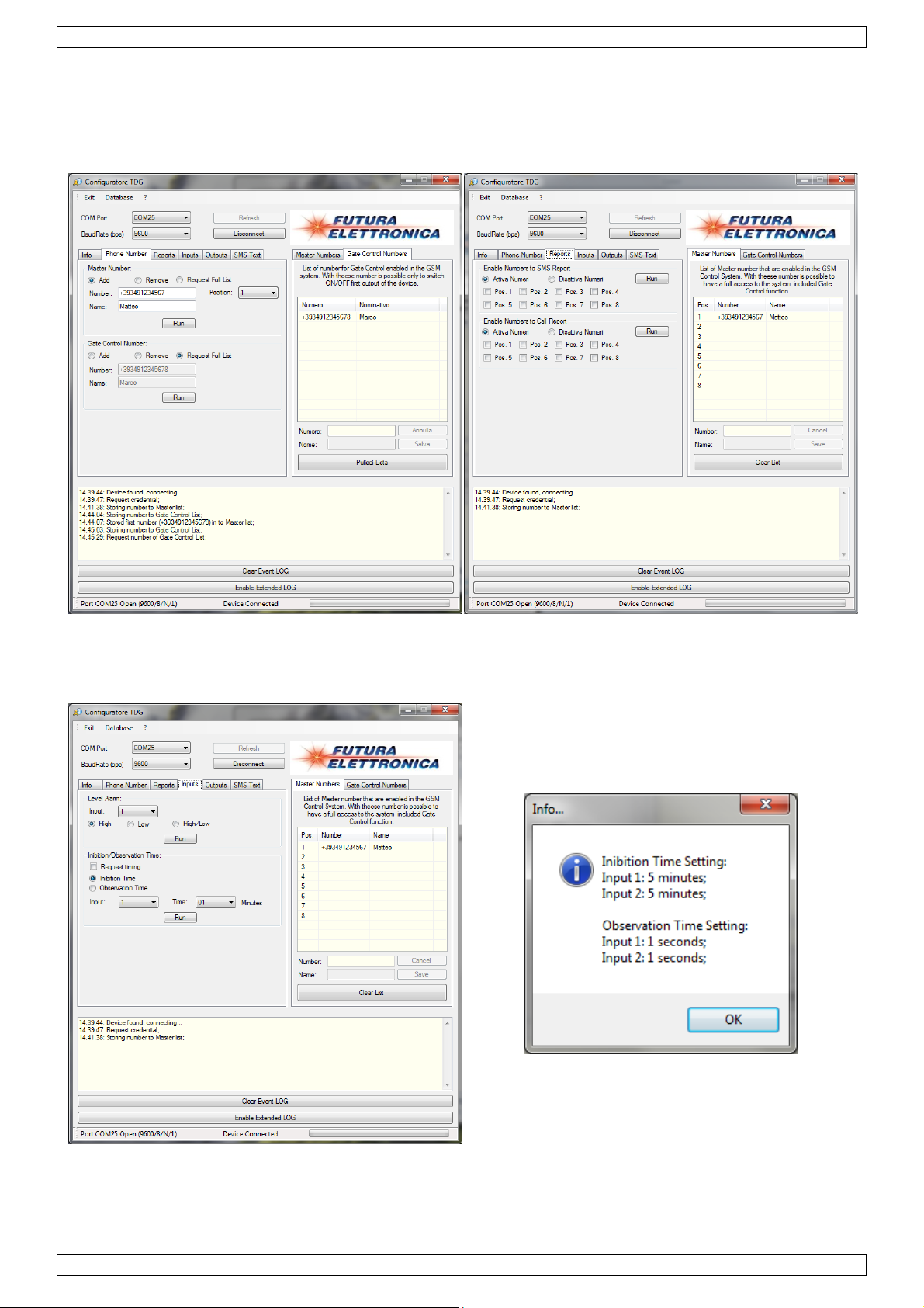
• The “Phone Number” tab [D] is used to manage phone numbers. Store or delete numbers, or request a
full list (shown on the right). The overview window has two tabs, one for “Master Numbers” [D] and
another for “Gate Control Numbers” [E].
Each action must be confirmed.
• Use the tab “Notice” [F] to enable or disable numbers on specific positions in the list. Enable to let them
receive SMS or alarm calls.
• Configure the activation logic (high/low/switch-over) of the two inputs in the tab “Inputs” [G].
Check the “Request timing” checkbox and click “Run” to see the current settings in a pop-up window
[H].
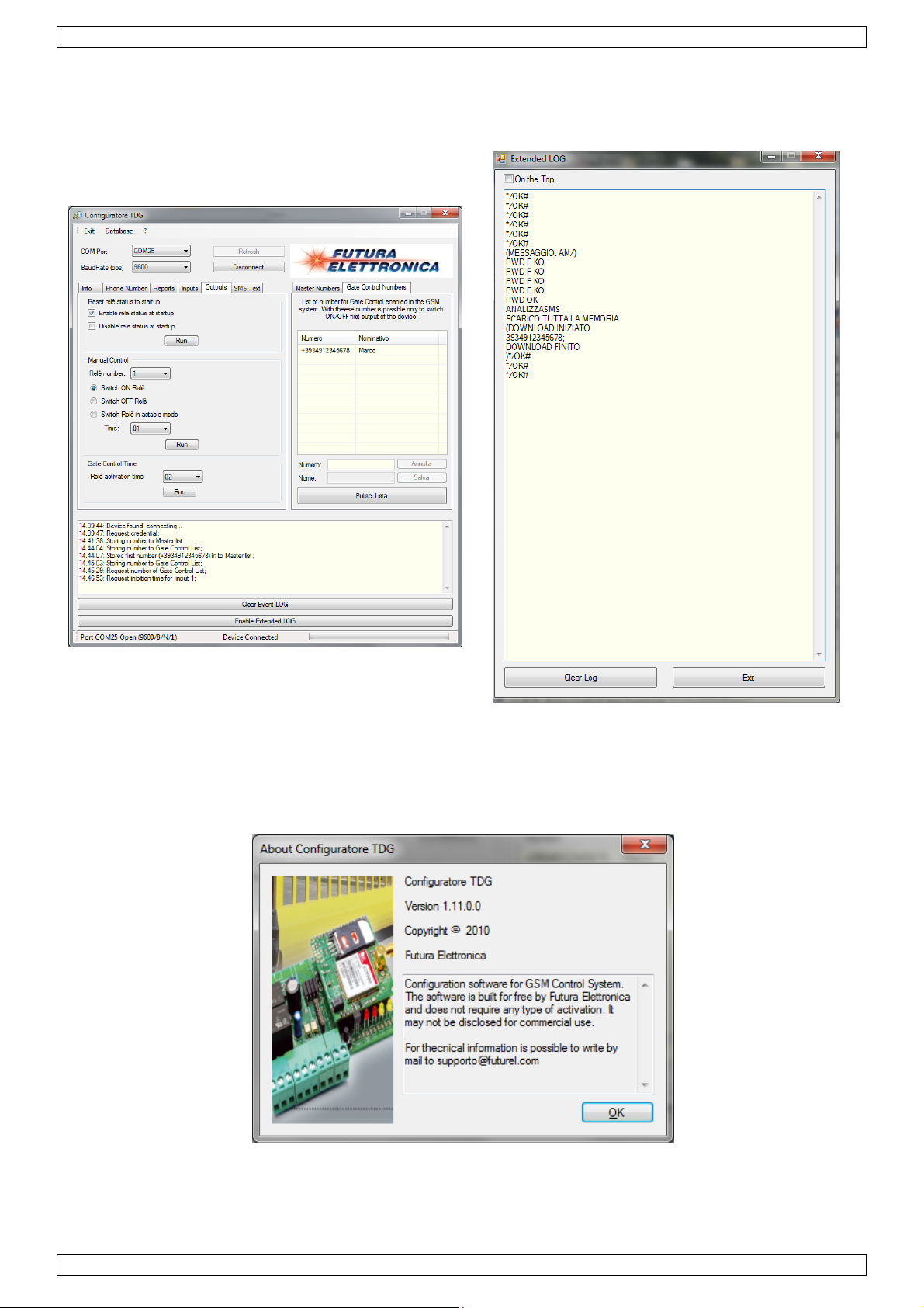
• The “Outputs” tab [I] is used to control the relays manually.
• In every window it is possible to see an extended log showing all communication that goes through the
communication port. Click on “Enable extended LOG” at the bottom of the screen. The extended log
window pops up [J].
and search for the product ID HAMGSM133/USB.
V. 02 – 15/05/2012 14 ©Velleman nv
Page 15

HAMGSM133
9. Troubleshooting
Problem Possible reason Possible solution
Green LED LD5 is off No supply tension or inverted
polarity
Green LED LD5 flashes
cyclically at 1 Hz frequency
The device does not send a reply to the
configuration SMS
During the first start-up LEDs LD1 and
LD3 do not light up alternatively
The device does not react to the call
from an enabled number
The device cannot engage in the GSM
network
No GSM network available or signal
not strong enough
Reply to the message with
command RISP is disabled or there
is no credit in the SIM Card.
The device has already been
started
The mobile used for the call has a
hidden ID
The PIN on the SIM Card has not
been disabled
Check power supply cable
Change the position of the external
GSM antenna
Do not use the RISP command in
the SMS, or recharge the SIM Card.
Completely reset the device using
the RES command.
Enable sending caller ID on the
used mobile phone
Disable the PIN request from the
SIM Card
10. Technical specifications
GSM/GPRS module SIM900 Quad (850/900/1800/1900MHz)
GPRS multi-slot class 10/8
mobile station class B
output power class 4 2W @ 850-900MHz
class 1 1W @ 1800-1900MHz
power supply 9 to 32 Vdc stabilized (or Li-Ion battery 800~1000mAh (not included))
current 50mA (idle), 1A max.
relay outputs 2 (to control low tension loads), type SELV (<60Vdc)
max. current relay contacts 10A
digital inputs 2 (logic 1 = 5~32Vdc; logic 0 = 0Vdc
master users 8
dimensions 103 x 67 x 28mm (L x W x H)
weight ±100g
operating temperature -10 ~ 55°C (14 ~ 131°F)
Use this device with original accessories only. Velleman nv cannot be held responsible in
the event of damage or injury resulted from (incorrect) use of this device.
For more info concerning this product and the latest version of this user manual, please
visit our website www.velleman.eu
The information in this manual is subject to change without prior notice.
© COPYRIGHT NOTICE
This manual is copyrighted. The copyright to this manual is owned by Velleman nv. All worldwide
rights reserved. No part of this manual may be copied, reproduced, translated or reduced to any electronic
medium or otherwise without the prior written consent of the copyright holder.
.
V. 02 – 15/05/2012 15 ©Velleman nv
Page 16

.
aBeDa
hafw
t
.3.4.
o
p
V
e
m
y
g
e
c
g
t
w
d
e
d
e
a
g
s
s
n
m
e
e
a
i
r
o
V
n
g
e
n
z
n
t
a
r
h
i
b
o
t
v
p
n
n
h
d
d
m
c
c
e
t
t
e
e
n
n
c
e
a
n
M
d
R
p
r
f
h
n
e
r
h
a
e
d
s
v
b
t
c
e
v
o
k
n
x
r
h
k
e
e
c
H
R
t
k
e
e
t
e
a
g
t
d
h
e
v
o
n
p
s
n
i
n
e
e
n
e
e
e
3
N
a
a
g
a
r
a
h
e
v
a
e
V
h
e
i
v
c
l
e
D
e
j
e
n
e
u
o
r
s
v
e
s
n
h
u
a
k
e
w
e
k
v
v
j
c
e
d
k
g
a
p
d
t
g
z
u
i
r
)
d
w
e
c
w
e
d
w
e
n
m
b
d
e
n
e
f
e
u
d
,
AMGSM1
3
1
Inlei
A
n alle ing
langrijke
nk u voor u
be
schadigd tij
sc
ade door h
ijzen voor
Di
toestel w
sc
hakelen vi
2
Veili
Dit s
weg
batt
tere
bren
Heb
Ho
Er
re
ding
zetenen v
ilieu-info
mbool op
eworpen, d
rijen) niet
htkomen v
en. Respec
u vragen,
aankoop!
ens het tra
t negeren
efecten of
rd ontwor
het GSM
heidsi
ud buiten
zijn geen
erveonder
GEB
n de Euro
matie bet
et toestel o
t toestel sc
ij het gewo
or recyclag
eer de plaa
contactee
Lees deze
nsport, inst
an bepaald
roblemen
pen om va
etwerk al
structie
et bereik
oor de ge
elen, con
UIKE
ese Unie
effende di
de verpak
ade kan to
e huishoud
. U moet di
tselijke mili
dan de pl
andleiding
lleer het da
richtlijnen
ie hier rech
nop afstan
ook voor
s
an kinder
ruiker ver
acteer uw
SHA
product
ing geeft a
brengen aa
lijke afval;
toestel na
uwetgevin
atselijke
rondig voo
n niet en ra
in deze han
streeks ver
elektrisc
et opvrag
n en onbe
angbare o
dealer.
DLEI
n dat, als h
n het milieu
het moet bi
r uw verdel
.
utoriteite
u het toest
dpleeg uw
dleiding en
band mee h
e en elekt
n van de
oegden.
nderdelen
ING
t na zijn le
. Gooi dit to
een gespe
r of naar e
betreffen
l in gebrui
dealer. De
w dealer z
uden.
onische a
tatus van
in dit toes
enscyclus
estel (en ev
ialiseerd b
n lokaal re
e de ver
neemt. W
arantie gel
l de verant
paraten in
e ingang
el. Voor o
ordt
entuele
drijf
yclagepunt
ijdering.
rd het toest
t niet voor
oordelijkh
of uit te
n via SMS.
derhoud o
el
id
Be
• De HA
• Koppe
• De tec
• Alvore
worde
Alge
• Leer e
• Om v
heeft
• Gebru
• De ga
dealer
mee h
• Noch
incide
bezit,
cherm tege
MGSM133
l het toestel
hnische spe
ns het toest
.
ene ri
Besche
Besch
van di
rst de func
iligheidsred
angebracht
k het toest
antie geldt
zal de vera
uden.
elleman no
teel of onr
ebruik of f
n regen, vo
oet voor g
los van de
ificaties m
el te gebrui
htlijne
rm tegen e
rm dit toe
toestel.
ies van het
nen mag u
valt niet on
l enkel waa
iet voor sc
twoordelij
h zijn verd
chtstreeks)
len van dit
htigheid en
bruik ingeb
oeding voo
eten te alle
en dient de
treme tem
stel tegen
toestel ken
geen wijzig
der de gara
voor het g
ade door h
heid afwijze
lers kunne
– van welk
product.
opspattend
uwd worde
raleer het a
tijde nage
uitgebreid
eraturen en
chokken.
en voor u
ngen aanbr
tie.
maakt is. B
t negeren
n voor defe
aansprake
aard dan o
e vloeistoff
n in een ge
n te raken.
leefd worde
gebruikers
stof.
ermijd br
et gaat geb
ngen. Sch
j onoordeel
an bepaald
ten of prob
ijk gesteld
ok (financie
n.
chikte behu
.
andleiding
te kracht
ruiken.
de door wij
undig gebr
richtlijnen
lemen die h
orden voo
l, fysisch…
izing (niet
elezen en
tijdens de
igingen die
ik vervalt
in deze han
er rechtstre
schade (bu
voortvloei
eegelev.).
egrepen te
bediening
de gebruik
e garantie.
dleiding en
eks verban
itengewoon
nd uit het
r
w
Vere
V
lgende ond
• Voedi
• Geldig
• Behui
O
tioneel:
• USB-i
oor deze in
V.
02 – 15/05/2
isten
rdelen zijn
g (9Vdc tot
e SIM-kaart
ing
terface HA
erface kan
012
iet meegel
max. 32Vd
GSM133/
e driver-so
verd en di
, gestabilis
USB.
ftware gevo
nen afzond
erd)
nden worde
16
rlijk aange
op: www.
ocht te wor
elleman.be
en door de
gebruiker:
©Vellema
nv
Page 17

HAMGSM133
5. Overzicht
Raadpleeg de afbeeldingen op pagina 2 van deze handleiding.
1 voedingsaansluiting 3 SIM-kaart (not meegelev.)
2 USB interface (optioneel)* 4 Antenne-aansluiting
* HAMGSM133/USB, niet meegeleverd.
O1 uitgang 1 I1 ingang 1
O2 uitgang 2 I2 ingang 2
LD1 relais 1 actief
LD2 Relais 2 actief
LD3 Ingang 1 actief (logische voorwaarde voldaan)
LD4 Ingang 2 actief (logische voorwaarde voldaan)
LD5 GSM netwerk verbindingsstatus
U1 zender LED U3 mini USB aansluiting
U2 ontvanger LED
6. Installatie
• Indien van toepassing, installeer de USB interface HAMGSM133/USB [2] (niet meegelev.). De mini
USB-aansluiting moet zich bovenaan bevinden.
• Schuif een geldige SIM-kaart [3] in het slot. Zorg ervoor dat de Pincode functie van de SIM-kaart
uitgeschakeld is. Gebruik een gewone GSM om dit te doen.
• Verbind de antenne met de antenneaansluiting [4].
• Maak de gewenste verbindingen (I1, I2, O1, O2). Verbind enkel een SELV (Safety Extra Low Voltage,
extra lage veiligheidsspanning) belasting met de uitgangen. Spanning op de contacten van elk relais
mag maximaal 60Vdc bedragen, schakelstroom op de relais maximaal 10A (kortstondige piek). De
maximale spanning op de digitale ingangen is maximum 32Vdc.
• Sluit de voeding aan [1] (niet meegelev.). Gebruik een gesta biliseerde stroombegrensde voeding (niet
meegelev.) die 9~32Vdc en minstens 500mA stroom levert (moet bestand zijn tegen 1A
absorptiepieken). Merk op dat de centrale pin positief i s.
• Sluit de behuizing (niet meegelev.).
7. Inleiding
• De HAMGSM133 is een bi-directionele bedieningsmodule waarmee vanop afstand twee relais (in
mono-stabiele of bi-stabiele modus) kunnen bediend worden door gebruik te maken van speciale SMS
commandoberichten gestuurd door eender welke mobiele telefoon.
• Geheugen voor 8 telefoonnummers naar dewelke SMS berichten en/of beltonen kunnen verstuurd
worden wanneer de ingangsstatus veranderd (hoofdlijst).
• Het is ook mogelijk om de HAMGSM133 als automatische deuropener te gebruiken, bestuurd door tot
200 opgegeven telefoonnummers (deuropenerlijst).
• Om de programmatie te vereenvoudigen kan een USB interface module aangesloten worden. De
HAMGSM133 kan dan geprogrammeerd worden met behulp van een PC (niet meegelev.) en
downloadbare software. De module hiervoor dient echter afzonderlijk aangekocht te worden. Bestelcode
HAMGSM133/USB.
8. Configuratie
Er zijn 3 manieren om het toestel in te stellen:
• Via telefoon (enkel bij opstarten)
• Via SMS
• Via USB (USB-interface vereist, niet meegelev.)
8.1 Via telefoon (enkel bij opstarten)
Zodra de voeding aangesloten wordt zal LD5 beginnen knipperen (1x per seconde). De HAMGSM133 probeert
nu een verbinding te maken met het GSM netwerk. Zodra de verbinding gemaakt is knippert LD5 om de 2
seconden. Na de initialisatie (die enkele seconden kan duren) lichten beurtelings de gele leds LD3 en LD4 op
om aan te geven dat het toestel in ‘configuratie via telefoon’ wachtstatus staat. Indien binnen de 3 minuten
een telefoongesprek ontvangen wordt wordt het nummer opgeslagen (om later een antwoord-SMS te kunnen
sturen) in het eerste geheugen. LD3 en LD4 gaan uit.
V. 02 – 15/05/2012 17 ©Velleman nv
Page 18

HAMGSM133
Opmerking: de identificatie van de beller mag niet verborgen zijn op de gebruikte mobiele telefoon (nummer
van de beller moet zichtbaar zijn wanneer naar een andere GSM gebeld wordt).
Na de 3 minuten wachtstatus gaan de gele leds uit en wacht het toestel op een configuratie-SMS.
8.2 Via SMS
Deze mode benut alle voordelen van het toestel, onder andere schakelen van uitgangen, opvragen van de
status van uitgangen, toevoegen van extra telefoonnummers om de relais aan te sturen, toevoegen van
nummers voor de deur-open functie, ontvangen van antwoordberichten, wijzigen van uitgangssignaal-tijdstip
en meer algemeen, stel alle parameters van de HAMGSM133 in via eenvoudige SMS’en. Ook het volledige
terugzetten naar fabrieksinstellingen behoort tot de mogelijkheden. De syntax van de beschikbare
commando’s staat hierna.
8.3 SMS syntax
• Commando’s en instellingen kunnen vanaf eender welke mobiele telefoon doorgesturud worden zolang
het bericht het paswoord bevat.
• Voor sommige commando’s is een paswoord niet nodig indien het commando verstuurd werd vanaf een
telefoonnummer dat opgeslagen is in de HAMGSM133. Sommige commando’s die kritische informatie
wijzigen hebben echter altijd een paswoord nodig.
• De HAMGSM133 stuurt een bevestiging of de gevraagde informatie via SMS.
• Meerdere commando’s kunnen in één SMS gebundeld worden door ze te scheiden door een komma.
• Opmerking: commando’s bevatten nooit spaties!
Een overzicht van alle beschikbare SMS-commando’s is hieronder weergegeven.
Wachtwoord wijzigen
Wachtwoord Vereist
Syntax PWDxxxxx;pwd
xxxxx = nieuw wachtwoord (5 cijfers)
pwd = huidige wachtwoord (standaard = 12345)
Voorbeeld PWD54321;12345
Telefoonnummer bewaren
Wachtwoord Vereist bij overschrijven of vanaf ongekend toestel
Syntax NUMx+YYnnnnnnnnnn;pwd
YY = landencode
x = positie van het nummer in de lijst (1~8)
nnnnnnnnnn = telefoonnummer (max. 19 cijfers)
pwd = huidige wachtwoord (standaard = 12345)
Voorbeeld NUM7+324851234567;12345
Result Nummer +324851234567 wordt opgeslagen op positie 7 in the hoofdlijst.
Telefoonnummer verwijderen
Wachtwoord Vereist
Syntax NUMx;pwd
x = positie van het nummer in de lijst (1~8)
pwd = huidige wachtwoord (standaard = 12345)
Voorbeeld NUM5;12345
Resultaat Het nummer op positie 5 wordt verwijderd uit de hoofdlijst.
Lijst opgeslagen nummers
Wachtwoord Vereist
Syntax NUM?;pwd
pwd = huidige wachtwoord (standaard = 12345)
Voorbeeld NUM?;12345
Resultaat Toon de hoofdlijst.
V. 02 – 15/05/2012 18 ©Velleman nv
Page 19

HAMGSM133
Fabrieksinstellingen
Wachtwoord Vereist
Syntax RES;pwd
pwd = huidige wachtwoord (standaard = 12345)
Voorbeeld RES;12345
Kies nummers die SMS zullen ontvangen
Wachtwoord Vereist
Syntax SMSxxxxxxxx:ON;pwd
xxxxxxxx = positie van het nummer in de lijst (1~8)
pwd = huidige wachtwoord (standaard = 12345)
Voorbeeld SMS15:ON;12345
Resultaat Telefoonnummers op plaatsen 1 en 5 zullen een SMS ontvangen wanneer de
status van de ingangen wijzigt. Andere nummers blijven ongewijzigd.
Standaard zullen alle 8 telefoonnummers een SMS ontvangen.
Kies nummers die geen SMS zullen ontvangen
Wachtwoord Vereist
Syntax SMSxxxxxxxx:OFF;pwd
xxxxxxxx = positie van het nummer in de lijst (1~8)
pwd = huidige wachtwoord (standaard = 12345)
Voorbeeld SMS27:OFF;12345
Resultaat Telefoonnummers op plaatsen 2 en 7 zullen geen SMS ontvangen wanneer de
status van de ingangen wijzigt. Andere nummers blijven ongewijzigd.
Kies nummers die een beltoon zullen ontvangen
Wachtwoord Vereist
Syntax VOCxxxxxxxx:ON;pwd
xxxxxxxx = positie van het nummer in de lijst (1~8)
pwd = huidige wachtwoord (standaard = 12345)
Voorbeeld VOC15:ON;12345
Resultaat Telefoonnummers op plaatsen 1 en 5 zullen een beltoon ontvangen wanneer
de status van de ingangen wijzigt. Andere nummers blijven ongewijzigd.
Standaard zullen alle 8 telefoonnummers beltonen ontvangen.
Kies nummers die geen beltoon zullen ontvangen
Wachtwoord Vereist
Syntax VOCxxxxxxxx:OFF;pwd
xxxxxxxx = positie van het nummer in de lijst (1~8)
pwd = huidige wachtwoord (standaard = 12345)
Voorbeeld VOC36:OFF;12345
Resultaat Telefoonnummers op plaatsen 3 en 6 zullen geen beltoon ontvangen wanneer
de status van de ingangen wijzigt. Andere nummers blijven ongewijzigd.
Stel logisch niveau hoog alarm in (ingang onder spanning)
Wachtwoord niet van toepassing
Syntax LIVx:A
x = 1 (ingang 1) of 2 (ingang 2)
Voorbeeld LIV2:A
Resultaat Stel het alarm niveau op ingang 2 in op hoog: het alarm wordt geactiveerd
zodra ingang 2 onder spanning komt. Standaard zijn beide ingangen
ingesteld op niveau hoog.
Stel logisch niveau laag alarm in (ingang niet onder spanning)
Wachtwoord niet van toepassing
Syntax LIVx:B
x = 1 (ingang 1) of 2 (input 2)
Voorbeeld LIV1:B
V. 02 – 15/05/2012 19 ©Velleman nv
Page 20

HAMGSM133
Resultaat Stel het alarm niveau op ingang 1 in op laag: het alarm wordt geactiveerd
zodra ingang 1 niet langer onder spanning staat.
Stel logisch niveau alarm in op omschakelen (alarm zodra toestand wijzigt)
Wachtwoord niet van toepassing
Syntax LIVx:V
x = 1 (ingang 1) of 2 (ingang 2)
Voorbeeld LIV1:V
Resultaat Wanneer de spanning op ingang 1 wijzigt, bv. van laag naar hoog, dan wordt
het alarm geactiveerd.
Aanvraag logisch alarminstelling
Wachtwoord niet van toepassing
Syntax LIV?
Voorbeeld LIV?
Resultaat Toon de logische alarminstellingen van beide ingangen.
Vertragingstijd ingang 1
Wachtwoord niet van toepassing
Syntax INI1:mm
mm = tijd in minuten (00~59)
Voorbeeld INI1:02
Resultaat Na activering van het alarm zal het toestel het alarmniveau van ingang 1 niet
controleren gedurende 2 minuten (vertragingstijd). Standaard = 5 minuten
Vertragingstijd ingang 2
Wachtwoord niet van toepassing
Syntax INI2:mm
mm = tijd in minuten (00~59)
Voorbeeld INI2:15
Resultaat Na activering van het alarm zal het toestel het alarmniveau van ingang 2 niet
controleren gedurende 15 minuten (vertragingstijd). Standaard = 5 minuten
Controle vertragingstijden
Wachtwoord niet van toepassing
Syntax INI?
Voorbeeld INI?
Resultaat Toon de vertragingstijden op beide ingangen.
Reset wachttijd voor ingang 1
Wachtwoord niet van toepassing
Syntax TIZ1x
x = 0 (geen reset) of 1 (reset)
Voorbeeld TIZ11
Resultaat Wachttijd wordt gereset op ingang 1 wanneer ingang 1 inactief is. Standaard
= geen reset
Reset wachttijd voor ingang 2
Wachtwoord niet van toepassing
Syntax TIZ2x
x = 0 (geen reset) of 1 (reset)
Voorbeeld TIZ20
Resultaat Wachttijd wordt niet gereset op ingang 1 wanneer ingang 2 inactief is.
Standaard = geen reset
V. 02 – 15/05/2012 20 ©Velleman nv
Page 21

HAMGSM133
Controle status reset-functie
Wachtwoord niet van toepassing
Syntax INI?
Voorbeeld INI?
Resultaat Toon de status van de reset-functie op de ingangen.
Observatietijd ingang 1
Wachtwoord niet van toepassing
Syntax OSS1:ss
ss = tijd in seconden(00~59)
Voorbeeld OSS:08
Resultaat Het alarm op ingang 1 moet gedurende 8 seconden aanwezig zijn alvorens
het alarm doorgegeven wordt. Standaard = 1 seconde
Observatietijd ingang 2
Wachtwoord niet van toepassing
Syntax OSS2:ss
ss = tijd in seconden(00~59)
Voorbeeld OSS2:15
Resultaat Het alarm op ingang 2 moet gedurende 15 seconden aanwezig zijn alvorens
het alarm doorgegeven wordt. Standaard = 1 seconde
Controle observatietijd
Wachtwoord niet van toepassing
Syntax OSS?
Voorbeeld OSS?
Resultaat Toon de status van de observatietijden op beide ingangen.
Inhoud alarm-SMS wanneer spanning op ingang 1 hoog is
Wachtwoord niet van toepassing
Syntax TIN1A:xxxxxxxx
xxxxxxxx = bericht (max. 100 karakters, allemaal hoofdletters)
Voorbeeld TIN1A: SPANNING OP INGANG 1
Resultaat Wanneer spanning op ingang 1 gedetecteerd wordt dan wordt een SMS met
als tekst “SPANNING OP INGANG 1” verstuurd. Standaard: ALARM! INPUT 1
HIGH
Opmerking gebruik geen puntkomma (;) in het bericht
Inhoud alarm-SMS wanneer spanning op ingang 1 laag is
Wachtwoord niet van toepassing
Syntax TIN1B:xxxxxxxx
xxxxxxxx = bericht (max. 100 karakters, allemaal hoofdletters)
Voorbeeld TIN1B1: GEEN SPANNING OP INGANG 1
Resultaat Wanneer geen spanning op ingang 1 gedetecteerd wordt dan wordt een SMS
met als tekst “GEEN SPANNING OP INGANG 1” verstuurd. Standaard:
ALARM! INPUT 1 LOW
Opmerking gebruik geen puntkomma (;) in het bericht
Inhoud alarm-SMS wanneer spanning op ingang 2 hoog is
Wachtwoord niet van toepassing
Syntax TIN2A:xxxxxxxx
xxxxxxxx = bericht (max. 100 karakters, allemaal hoofdletters)
Voorbeeld TIN2A: SPANNING OP INGANG 2
Resultaat Wanneer spanning op ingang 1 gedetecteerd wordt dan wordt een SMS met
als tekst “SPANNING OP INGANG 2” verstuurd. Standaard: ALARM! INPUT 2
HIGH
Opmerking gebruik geen puntkomma (;) in het bericht
V. 02 – 15/05/2012 21 ©Velleman nv
Page 22

HAMGSM133
Inhoud alarm-SMS wanneer spanning op ingang 2 laag is
Wachtwoord niet van toepassing
Syntax TIN2B:xxxxxxxx
xxxxxxxx = bericht (max. 100 karakters, allemaal hoofdletters)
Voorbeeld TIN2B: GEEN SPANNING OP INGANG 2
Resultaat Wanneer geen spanning op ingang 2 gedetecteerd wordt dan wordt een SMS
met als tekst “GEEN SPANNING OP INGANG 2” verstuurd. Standaard:
ALARM! INPUT 2 LOW
Opmerking gebruik geen puntkomma (;) in het bericht
Een relaisuitgang activeren
Wachtwoord niet van toepassing
Syntax OUTx:ON
x = 1 (uitgang 1) of 2 (uitgang 2)
Voorbeeld OUT1:ON
Resultaat Activateer uitgang relais 1
Een relaisuitgang deactiveren
Wachtwoord niet van toepassing
Syntax OUTx:OFF
x = 1 (uitgang 1) of 2 (uitgang 2)
Voorbeeld OUT2:OFF
Resultaat Deactiveer uitgang relais 2
De toestand van een relais tijdelijk wijzigen
Wachtwoord niet van toepassing
Syntax OUTx:ss
x = 1 (uitgang 1) of 2 (uitgang 2)
ss = tijd in seconden (00~59)
Voorbeeld OUT1:10
Resultaat Deactiveer (wanneer reeds actief) of activeer (wanneer niet actief) uitgang
relais 1 voor de volgende 10 seconden.
Status uitgangen opvragen
Wachtwoord niet van toepassing
Syntax STA?
Voorbeeld STA?
Resultaat Toon de status van de uitgangsrelais.
Opslaan en terugzetten relaisstatus na stroomonderbreking
Wachtwoord niet van toepassing
Syntax RIPx
x = 0 (niet actief) of 1 (actief)
Voorbeeld RIP1
Resultaat De status van de relais wordt automatisch opgeslagen wanneer een
stroomonderbreking optreedt en teruggezet zodra de spanning herstelt is.
Standaard: 1 (actief)
Opvragen huidige instelling back-up relaisstatus
Wachtwoord niet van toepassing
Syntax RIP?
Voorbeeld RIP?
Resultaat Toon de status van de back-upinstelling.
V. 02 – 15/05/2012 22 ©Velleman nv
Page 23

HAMGSM133
Inhoud opstart- SMS
Wachtwoord niet van toepassing
Syntax TSU:xxxxxxxx
xxxxxxxx = bericht (max. 100 karakters, allemaal hoofdletters)
Voorbeeld TSU: SYSTEM START-UP
Resultaat Indien actief (zie commando AVVx) wordt dit bericht gestuurd naar het
telefoonnummer op de eerste plaats in de lijst. Standaard: SYSTEM STARTUP
Opmerking gebruik geen puntkomma (;) in het bericht
Activeer opstart-SMS
Wachtwoord niet van toepassing
Syntax AVVx
x = 0 (niet actief) of 1 (actief)
Voorbeeld AVV1
Resultaat Er wordt een SMS gestuurd naar het telefoonnummer op de eerste plaats in
de lijst zodra het toestel (her-)opstart. Standaard: 0 (niet actief)
Activeer deurcontrolefunctie (relais 1)
Wachtwoord niet van toepassing
Syntax TAC:ss
ss = tijd in seconden (00~59)
Voorbeeld TAC:12
Resultaat Wanneer een oproep ontvangen wordt van één van de 200 mogelijke
deurcontrole-nummers of één van de 8 nummers in de hoofdlijst dan zal het
relais actief worden gedurende 12 seconden. Standaard: 3 seconden
Opmerking wanneer de tijd op 00 ingesteld wordt dan zal het relais in bi-stabiele modus
werken; relais 1 zal zijn status omschakelen telkens er een oproep ontvangen
wordt.
Opslaan deurcontrole-nummers (max. 200)
Wachtwoord Vereist
Syntax MAC+YYnnnnnnnnnn;pwd
YY= landencode
nnnnnnnnnn = telefoonnummer (max. 19 cijfers)
pwd = huidige wachtwoord (standaard = 12345)
Voorbeeld MAC+324851234567;12345
Opmerking in de lijst van deurcontrole-nummers wordt geen rekening gehouden met de
plaats.
Verwijderen deurcontrole-nummers
Wachtwoord Vereist
Syntax DAC+YYnnnnnnnnnn;pwd
YY= landencode
nnnnnnnnnn = telefoonnummer om te wissen
pwd = huidige wachtwoord (standaard = 12345)
Voorbeeld DAC+324851234567;12345
Uitschakelen antwoord- SMS
Wachtwoord niet van toepassing
Syntax RISP (commando’s)
Commando's = reeks commando’s gescheiden door komma (,)
Voorbeeld RISP, OUT1:ON, DAC, INI1:10
V. 02 – 15/05/2012 23 ©Velleman nv
Page 24

HAMGSM133
8.4 Via USB (USB-interface nodig, niet meegeleverd)
Op deze manier is het mogelijk om op een eenvoudige wijze met behulp van een computer (met de juiste
software) verbonden met de USB-interface (niet meegelev., ref. HAMGSM133/USB) in te stellen.
Het is mogelijk om alle programmatie te beheren alsook de lijst van toegestane gebruikers te wijzigen. Dit
versnelt aanzienlijk de initiële instelling en bespaart SMS-kosten. Na het starten van de software controlleer of
de communicatiesnelheid ingesteld staat op 9600 Baud (8, N, 1).
Raadpleeg de uitgebreide gebruikershandleiding voor meer informatie over de installatie en het gebruik van
de software. Download de (Engelse) software van: www.velleman.be
Opmerking: Wanneer er een verbinding is met de PC, is het beheer via SMS uitgeschakeld.
Software installeren
• Ga naar www.velleman.be
• Op de productpagina, klik op Software en vervolgens op Save.
• Start het setup-bestand en volg de instructies op het scherm.
• Wanneer de installatie voltooid is, start de software op. Het configuratiescherm [A] verschijnt.
• Verbind de HAMGSM133 met de USB poort van de computer d.m.v. een geschikte kabel (niet
meegelev.).
• Kies de gepaste COM poort (bovenaan links). Klik op ‘refresh’ om de lijst met beschikbare poorten
opnieuw op te bouwen.
• Klik op ‘Connect’ (bovenaan midden) om de verbinding tot stand te brengen. Indien er reeds data
aanwezig is in de module dan wordt deze getoond.
• Indien er geen hoofdnummer aanwezig is in de module dan zal het bericht “Waiting for Call for Master
Number Storage” getoond worden in het berichtenvenster [B] (onderaan het scherm). Doe een oproep
naar de HAMGSM133 alvorens verder te gaan. Een bevestigingsbericht wordt getoond in het
berichtenvenster.
• Het configuratiescherm toont een aantal tabs.
• In het “Info” [C] tab wordt het modelnummer, de firmware versie en de IMEI (International Mobile
Equipment Identity) getoond. Het is ook mogelijk om in deze tab het paswoord te wijzigen.
Vooraleer settings kunnen gewijzigd worden moet het huidige paswoord ingegeven worden in het veld
“system password” en klik op “Save”.
Indien het toestel niet reageert op commando’s vanuit de computer, vergewis u er dan van dat het
paswoord opgeslagen in de PC hetzelfde is als dat in het programma.
• De “Phone Number” tab [D] wordt gebruikt om telefoonnummers te beheren. Sla nummers op of
verwijder ze, of toon de volledige lijst (rechts op het scherm). Het overzichtsvenster heeft twee tabs –
één voor “Master Numbers” [D] (hoofdnummers) en een ander voor “Gate Control Numbers” [E]
(deuropener-nummers).
Elke actie moet bevestigd (confirmed) worden.
• Gebruik de tab “Notice” [F] om nummers op specifieke locaties in de lijst te laten SMSen of
alarmoproepen ontvangen of niet.
• Configureer de activatielogica (hoog/laag/overgang) van de twee ingangen in de tab “Inputs” [G].
Vin de “Request timing” checkbox aan en klik op “Run” om de huidige instellingen in een pop-up
venster [H]te bekijken.
• De “Outputs” tab [I] wordt gebruikt om de relais manueel te bedienen.
• In elk venster is het mogelijk om een uitgebreide overzicht op te roepen waarin alle communicatie die
door de USB poort gaat getoond wordt. Klik op “Enable extended LOG” onderaan het scherm. Het
uitgebreide venster verschijnt [J].
en zoek naar de productnaam HAMGSM133/USB.
V. 02 – 15/05/2012 24 ©Velleman nv
Page 25

HAMGSM133
9. Probleemoplossing
Probleem Mogelijke reden Mogelijke oplossing
Groene led LD5 is uit Geen spanning of verkeerde polariteit. Controller voedingskabel.
Groene led LD5 flikkert
periodisch (1Hz frequentie)
Het toestel stuurt geen
antwoord op een configuratieSMS
Tijdens het opstarten lichten
leds LD1 en LD3 niet
beurtelings op
Het toestel reageert niet op
een oproep van een actief
nummer
Het toestel geraakt niet op het
GSM netwerk
Geen GSM network beschikbaar of signal
te zwak
Antwoord werd uitgeschakeld met het
RISP commando of belkrediet SIM kaart is
op.
Toestel is reeds opgestart. Reset het toestel volledig met het
De telefoon waarmee gebeld werd
verbergt de belleridentificatie (nummer)
De PIN-code op de SIM-kaart is nog actief Schakel de PIN-code op de SIM-
Verander de plaats van de externe
GSM antenne
Vermijd het gebruik van het RISP
commando of herlaad de SIM-kaart.
RES-commando.
Laat het tonen van de beller
(nummer) toe op de gebruikte GSM
kaart uit.
10. Technische specificaties
GSM/GPRS module SIM900 Quad (850/900/1800/1900MHz)
GPRS multislot klasse 10/8
mobiel station klasse B
Uitgangsvermogen class 4 2W @ 850-900MHz
class 1 1W @ 1800-1900MHz
voeding 9 tot 32 Vdc gestabiliseerd (of Li-Ion batterij 800~1000mAh (niet
meegelev.))
Stroom 50mA (niet in werking),1A max.
Relaisuitgangen 2 (ter controle van laagspanningsbelastingen), type SELV (<60Vdc)
max. stroom relais contacten 10A
digitale ingangen 2 (logic 1 = 5~32Vdc; logic 0 = 0Vdc
hoofdgebruikers 8
Afmetingen 103 x 67 x 28mm (L x B x H)
Gewicht ±100g
werktemperatuur -10 ~ 55°C (14 ~ 131°F)
Gebruik dit toestel enkel met originele accessoires. Velleman nv is niet aansprakelijk voor schade of
kwetsuren bij (verkeerd) gebruik van dit toestel.
Voor meer informatie omtrent dit product en de meest recente versie van deze handleiding, zie
www.velleman.eu.
De informatie in deze handleiding kan te allen tijde worden gewijzigd zonder voorafgaande
kennisgeving.
© AUTEURSRECHT
Velleman nv heeft het auteursrecht voor deze handleiding.
Alle wereldwijde rechten voorbehouden. Het is niet toegestaan om deze handleiding of gedeelten ervan over te
nemen, te kopiëren, te vertalen, te bewerken en op te slaan op een elektronisch medium zonder voorafgaande
schriftelijke toestemming van de rechthebbende.
V. 02 – 15/05/2012 25 ©Velleman nv
Page 26

.
uDeNo
p
tCe
m
.3.4.
sOp
P
o
s
t
y
e
o
e
a
m
a
t
u
s
r
naup
o
c
c
m
c
s
a
e
o
c
e
v
n
S
r
a
t
n
o
n
s
e
t
v
t
p
é
e
e
a
t
gé
e
e
n
l
o
p
v
s
t
o
c
M
t
r
n
p
x
s
a
a
m
)
t
t
u
n
m
d
a
n
t
v
a
r
t
u
s
V
m
H
C
a
e
v
u
s
v
u
e
d
l
e
r
v
e
e
a
r
g
g
r
n
n
é
3
M
e
e
t
u
c
a
t
g
è
e
n
a
o
e
é
é
a
t
s
e
I
p
n
é
c
e
é
e
t
d
r
z
e
r
r
i
f
e
p
l
e
u
r
t
c
.
i
e
q
a
.
o
t
e
t
a
e
s
e
r
e
e
r
e
s
(
s
u
n
s
o
e
e
o
AMGSM1
3
1
Intr
A
x résident
s informa
us vous re
l’a
pareil. Si l’
La
garantie ne
vo
re revende
t appareil a
co
me pour e
2
Con
Ce s
pollu
parm
Renv
resp
En c
Ga
Il
duction
de l'Unio
ions envir
mbole sur l'
r l'environ
i les déchet
yer les équ
cter la régl
s de ques
ercions de
ppareil a é
s’applique
r déclinera
été dévelop
nregistrer l’
ignes d
der hors de
’y a aucune
rès votre r
europée
nnementa
appareil ou
ement. Ne
municipau
ipements u
mentation l
ions, cont
otre achat
é endomm
as aux do
toute respo
pé pour (dé
tat des ent
sécuri
portée des
pièce main
vendeur.
NOTI
ne
les import
l'emballage
as jeter un
non sujets
agés à votr
ocale relati
cter les a
! Lire la pré
gé pendant
mages sur
nsabilité po
brancher d
rées par SM
é
enfants et
enable par
E D’E
ntes conc
indique que
appareil él
au tri sélec
fournisse
e à la prote
torités loc
ente notice
le transpor
enus en né
r les probl
s appareils
S.
es personn
’utilisateur.
PLO
rnant ce
l’éliminatio
ctrique ou
if ; une dé
r ou à un s
tion de l’en
les pour
attentivem
, ne pas l’in
ligeant cer
mes et les
électriques
s non auto
Commande
roduit
d’un appa
lectronique
hèterie trai
rvice de re
vironnemen
limination
nt avant la
staller et co
aines direct
éfauts qui
et électroni
isées.
des pièces
eil en fin d
(et des pile
era l’appar
yclage local
t.
mise en se
nsulter votr
ves de cett
n résultent.
ues par le
de rechang
vie peut
éventuelle
il en questi
. Il convient
vice de
revendeur
notice et
éseau GSM
e éventuell
)
n.
de
.
s
Pr
• Incorp
• Décon
• Les sp
• Il est
Dire
• Se fa
• Toute
modifi
• N’utili
• La gar
notice
résult
• Ni Vell
occasi
disfon
téger de la
orer le HAM
necter l’app
écifications
onseillé de
tives
Tenir à
Protég
iliariser av
modificatio
ations par
er qu’à sa f
ntie ne s’a
et votre re
nt.
eman ni se
nnel ou ind
tionnemen
pluie, de l’h
GSM133 da
reil de l’ali
echniques
lire et de co
nérales
l’écart de l
r contre les
c le fonctio
est interdit
e client ne
nction pré
plique pas
endeur décl
distributeu
irect) de na
de ce prod
midité et d
s un boitie
entation a
oivent être
mprendre l
poussière
chocs et le
nement av
e pour des
ombent pas
ue. Un usa
ux domma
inera toute
s ne peuve
ure quelco
it.
s projectio
approprié
ant de le t
respectées
mode d’em
t des temp
traiter avec
nt l’emploi.
aisons de s
sous la gar
e impropre
es survenu
esponsabili
t être tenu
que (financ
s d’eau.
vant premi
ucher.
n toutes ci
ploi détaillé
ratures ext
circonspect
curité. Les
ntie.
annule d'of
s en néglig
é pour les
responsab
ière, corpor
r usage (p
constances
avant prem
êmes.
on pendant
dommages
ice la garan
ant certain
roblèmes e
es d’endom
lle…) causé
s inclus).
ier usage d
l’opération.
ccasionnés
ie.
s directives
les défaut
magement
par posses
l’appareil.
par des
de cette
qui en
exceptionn
ion, usage
l,
u
Prér
Le
unités sui
• Alime
• Carte
• Boîtie
tionnel:
• Interf
our cette in
V.
02 – 15/05/2
quis
antes ne s
tation (9Vc
IM valable
ce USB HA
erface, voi
012
nt pas inclu
à max. 32
GSM133/
www.velle
es et doive
cc, stabilis
USB.
an.be
nt être ach
)
26
tées individ
ellement p
r l’utilisate
r:
©Vellema
nv
Page 27

HAMGSM133
5. Description
Se référer aux illustrations à la page 2 de cette notice.
1 connexion d’alimentation 3 carte SIM (pas livrée)
2 interface USB (optionnelle)* 4 connexion d’antenne
* HAMGSM133/USB, pas livré
O1 sortie 1 I1 entrée 1
O2 sortie 2 I2 entrée 2
LD1 relais 1 activé
LD2 relais 2 activé
LD3 entrée 1 activée (accomplit avec la condition logique)
LD4 entrée 2 activée (accomplit avec la condition logique)
LD5 état de connexion du réseau GSM
U1 récepteur LED U3 Mini connecteur USB
U2 émetteur LED
6. Installation
• Le cas échéant, installer l’interface USB HAMGSM133/USB [2] (pas livrée). S’assurer que le mini
connecteur USB soit mis dans la partie supérieure.
• Insérer une carte SIM valable [3] dans le lecteur. Veiller à ce que la fonction PIN de la carte SIM a été
désactivée. Utiliser un GSM normal pour cela.
• Connecter l’antenne avec la connexion d’antenne [4].
• Faire les connexions souhaitées (I1, I2, O1, O2). Connecter uniquement une charge TBTS (Très Basse
Tension de Sécurité) aux sorties. Tension appliquée sur les contacts de chaque relais ne peut pas
dépasser 10A (durée d'impulsion courte). Une tension maximale de 32Vcc est appliquée sur les entrées
numériques.
• Connecter l’alimentation [1] (pas livrée). Utiliser une alimentation à découpage stabilisée (pas livrée)
fournissant une tension de 9~32Vcc. et pouvant débiter un courant minimale de 500mA (résiste aux
crêtes d’absorption de 1A). A noter: la broche centrale est positive.
• Fermer le boîtier (pas livré).
7. Introduction
• Le HAMGSM133 est un module de télécommande bidirectionnelle permettant de piloter deux relais à
distance (en mode monostable ou bistable) grâce à des messages SMS envoyés depuis n’importe quel
téléphone portable.
• Mémorise jusqu'à huit numéros de téléphone vers lesquels peuvent être envoyés des SMS et/ou des
tonalités si l’état d’entrée change (liste principale).
• Le HAMGSM133 convient également comme récepteur du système de contrôle d’accès piloté par 200
numéros de téléphone indiqués (liste du système de contrôle d’accès).
• Pour faciliter la programmation, il est possible de connecter un module d’interface USB. Le
HAMGSM133 peut donc être programmé par un ordinateur (pas livré) et logiciel à télécharger mais
pour cela, le module doit être acheté individuellement. Code de commande: HAMGSM133/USB.
8. Configuration
Il y a 3 modes pour installer l’appareil
• Par téléphone (seulement lors la mise en marche)
• Par SMS
• Par USB (interface USB exigée, pas livrée)
8.1 Par téléphone (seulement lors la mise en marche)
Du moment que l’alimentation est connectée, LD5 va commencer à clignoter (1 x par seconde). Le
HAMGSM133 essaie maintenant à faire une connexion avec le réseau GSM. Du moment que la connexion a
été faite, LD5 clignote toutes les 2 secondes. Après initialisation (qui peut durer quelques secondes) les LED
jaunes LD3 et LD4 s’illuminent alternativement pour indiquer que l’appareil est en mode veille pendant 3
minutes. Si un appel téléphonique est reçu dans un délai de 3 minutes, le numéro est enregistré dans la
mémoire initiale (afin de pouvoir envoyer une réponse au SMS). LD3 et LD4 s’éteignent.
V. 02 – 15/05/2012 27 ©Velleman nv
Page 28

HAMGSM133
Attention: L’identité de l’appelant ne peut pas être cachée sur le portable utilisé (le numéro de l’appelant doit
être visible durant l’appel téléphonique vers un autre GSM).
Après les 3 minutes en mode veille, les LED jaunes s’éteignent et l’appareil attend un SMS de configuration.
8.2 Par SMS
Ce mode utilise tous les bénéfices de l’appareil entre autres la connexion des sorties, l’enregistrement d’état
de sorties, incorporation des numéros de téléphone supplémentaires pour le pilotage du relais, l’addition de
numéros de téléphone supplémentaires pour la fonction ouvre-porte, la réception de messages de réponse, la
modification du temps de signaux de sortie et le plus utilisé est l’ajustement de tous les paramètres du
HAMGSM133 par un simple SMS. Le retour au réglage par défaut appartient également aux possibilités. Voir
ci-dessous pour la syntaxe SMS.
8.3 Syntaxe SMS
• Les commandes et ajustements peuvent être envoyés depuis n’importe quel téléphone portable du
moment que le message contient un mot de passe.
• Pour certaines commandes, un mot de passe est inutile si la commande a été envoyée depuis un
numéro de téléphone enregistré dans le HAMGSM133. Toutefois certaines commandes contenant de
l’information importante ont toujours besoin d’un mot de passe.
• Le HAMGSM133 envoie une confirmation ou l’information demandée par SMS.
• Plusieurs commandes peuvent être groupées dans un seul SMS en les séparant d’une virgule.
• Attention : les commandes ne contiennent jamais d’espaces!
Un sommaire des commandes SMS disponibles est illustré ci-dessous.
Modifier mot de passe
Mot de passe requis
Syntaxe PWDxxxxx;pwd
xxxxx = nouveau mot de passe (5 chiffres)
pwd = mot de passé actuel (standard: 12345)
Exemple PWD54321;12345
Garder numéro de téléphone
Mot de passe requis pour écraser ou depuis un appareil inconnu
Syntaxe NUMx+YYnnnnnnnnnn;pwd
YY = code de pays
x = position du numéro dans la liste (1~8)
nnnnnnnnnn = numéro de téléphone (max. 19 chiffres)
pwd = mot de passé actuel (standard = 12345)
Exemple NUM7+324851234567;12345
Résultat Numéro +324851234567 sera mémorisé en position 7 dans la liste
principale.
Effacer les numéros de téléphone
Mot de passe requis
Syntaxe NUMx;pwd
x = position du numéro dans la liste (1~8)
pwd = mot de passé actuel (standard = 12345)
Exemple NUM5;12345
Résultat Le numéro en position 5 et supprimé de la liste principale.
Contrôler les numéros de téléphone enregistrés
Mot de passe requis
Syntaxe NUM?;pwd
pwd = mot de passé actuel (standard = 12345)
Exemple NUM?;12345
Résultat Afficher la liste principale.
V. 02 – 15/05/2012 28 ©Velleman nv
Page 29

HAMGSM133
Ajustements par défaut
Mot de passe requis
Syntaxe RES;pwd
pwd = mot de passe actuel (standard = 12345)
Exemple RES;12345
Sélectionner des numéros qui recevront un SMS
Mot de passe requis
Syntaxe SMSxxxxxxxx:ON;pwd
xxxxxxxx = position du numéro dans la liste (1~8)
pwd = mot de passe actuel (standard = 12345)
Exemple SMS15:ON;12345
Résultat Les numéros de téléphone en positions 1 et 5 recevront un SMS si l’état des
entrées change. Les autres numéros restent invariables. Tous les 8 numéros
de téléphone recevront un SMS par défaut.
Sélectionner des numéros qui ne recevront pas de SMS
Mot de passe requis
Syntaxe SMSxxxxxxxx:OFF;pwd
xxxxxxxx = position du numéro dans la liste (1~8)
pwd = mot de passé actuel (standard = 12345)
Exemple SMS27:OFF;12345
Résultat Les numéros de téléphone en positions 2 et 7 ne recevront pas de SMS si
l’état des entrées change. Les autres numéros restent invariables.
Sélectionner numéros qui recevront une tonalité
Mot de passe requis
Syntaxe VOCxxxxxxxx:ON;pwd
xxxxxxxx = position du numéro dans la liste (1~8)
pwd = mot de passe actuel (standard = 12345)
Exemple VOC15:ON;12345
Résultat Les numéros de téléphone en positions 1 et 5 recevront une tonalité si l’état
des entrées change. Les autres numéros restent invariables. Tous les 8
numéros de téléphone recevront une tonalité par défaut.
Sélectionner des numéros qui ne recevront pas de tonalité
Mot de passe requis
Syntaxe VOCxxxxxxxx:OFF;pwd
xxxxxxxx = position du numéro dans la liste (1~8)
pwd = mot de passé actuel (standard = 12345)
Exemple VOC36:OFF;12345
Résultat Les numéros de téléphone en positions 3 et 6 ne recevront pas de tonalité si
l’état des entrées change. Les autres numéros restent invariables.
Niveau logique: Alarme élevée (entrée sous tension)
Mot de passe Non applicable
Syntaxe LIVx:A
x = 1 (entrée 1) ou 2 (entrée 2)
Exemple LIV2:A
Résultat Ajuster le niveau d’alarme sur entrée 2 vers niveau élevé: l’alarme est
activée du moment qu’entrée 2 est mise sous tension. Les deux entrées sont
ajustées vers niveau ÉLEVÉ par défaut.
V. 02 – 15/05/2012 29 ©Velleman nv
Page 30

HAMGSM133
Niveau logique : Alarme faible (pas de tension sur entrée)
Mot de passe Non applicable
Syntaxe LIVx:B
x = 1 (entrée 1) ou 2 (entrée 2)
Exemple LIV1: B
Résultat Ajuster le niveau d’alarme sur entrée 1 vers niveau faible : l’alarme est
activée du moment qu’entrée 1 n’est plus mise sous tension.
Niveau logique : marge pour alarme (alarme du moment que la tension d’entrée change)
Mot de passe Non applicable
Syntaxe LIVx:V
x = 1 (entrée 1) ou 2 (entrée 2)
Exemple LIV1:V
Résultat Si la tension sur entrée 1 change, p.ex. de basse vers haute, l’alarme sera
activée.
Niveau : demande des paramètres d'alarme logiques
Syntaxe LIV?
Exemple LIV?
Résultat Afficher les paramètres d’alarme logiques des deux entrées.
Délai de temporisation entrée 1
Mot de passe Non applicable
Syntaxe INI1:mm
mm = temps en minutes (00~59)
Exemple INI1:02
Résultat Après activation de l’alarme, l’appareil ne contrôlera pas le niveau d’alarme
d’entrée 1 pendant 2 minutes (délai de temporisation). Par défaut = 5
minutes
Délai de temporisation entrée 2
Mot de passe Non applicable
Syntaxe INI2:mm
mm = temps en minutes (00~59)
Exemple INI2:15
Résultat Après activation de l’alarme, l’appareil ne contrôlera pas le niveau d’alarme
d’entrée 2 pendant 15 minutes (délai de temporisation). Par défaut = 5
minutes
Contrôle des délais de temporisation
Syntaxe INI?
Exemple INI?
Résultat Afficher les délais de temporisation sur les deux entrées.
Réinitialiser le délai de temporisation entrée 1
Mot de passe Non applicable
Syntaxe TIZ1x
x = 0 (ne pas réinitialiser) ou 1 (réinitialiser)
Exemple TIZ11
Résultat Le délai de temporisation est réinitialisé sur entrée 1 si entrée 1 est inactive.
Par défaut = pas de réinitialisation
Réinitialiser le délai de temporisation entrée 2
Mot de passe Non applicable
Syntaxe TIZ2x
x = 0 (ne pas réinitialiser) ou 1 (réinitialiser)
Exemple TIZ20
Résultat Délai de temporisation n’est pas réinitialisé sur entrée 1 si entrée 2 est
inactive. Par défaut = pas de réinitialisation
V. 02 – 15/05/2012 30 ©Velleman nv
Page 31

HAMGSM133
Contrôle d’état de la fonction-réinitialiser
Mot de passe Non applicable
Syntaxe INI?
Exemple INI?
Résultat Afficher l’état de la fonction de réinitialisation sur les entrées.
Temps d’observation entrée 1
Syntaxe OSS1:ss
ss = temps en secondes (00~59)
Exemple OSS:08
Résultat L’alarme sur entrée 1 doit être permanente pendant 8 secondes avant que
l’alarme soit transmise. Par défaut = 1 seconde
Temps d’observation entrée 2
Mot de passe Non applicable
Syntaxe OSS2:ss
ss = temps en secondes (00~59)
Exemple OSS2:15
Résultat L’alarme sur entrée 2 doit être permanente pendant 15 secondes avant que
l’alarme soit transmise. Par défaut = 1 seconde
Contrôle de temps d’observation
Mot de passe Non applicable
Syntaxe OSS?
Exemple OSS?
Résultat Afficher l’état des temps d’observation sur les deux entrées.
Texte d’alarme si entrée 1 est mise sous tension
Mot de passe Non applicable
Syntaxe TIN1A:xxxxxxxx
xxxxxxxx = message (max. 100 caractères, tous en lettres capitales)
Exemple TIN1A: TENSION SUR ENTRÉE 1
Résultat Si une tension est détectée sur entrée 1, un SMS avec le texte “TENSION
SUR ENTRÉE” est envoyé. Par défaut: ALARM! INPUT 1 HIGH
Remarque ne pas utiliser de point-virgule (;) dans le message
Texte d’alarme si entrée 1 n’est pas mise sous tension
Mot de passe Non applicable
Syntaxe TIN1B:xxxxxxxx
xxxxxxxx = message (max. 100 caractères, tous en lettres capitales)
Exemple TIN1B1: PAS DE TENSION SUR ENTRÉE 1
Résultat Aucune tension est détectée sur entrée 1. Si aucune tension est détectée sur
entrée 1, un SMS avec le texte “PAS DE TENSION SUR ENTRÉE 1” est
envoyé. Par défaut: ALARM! INPUT 1 LOW
Remarque ne pas utiliser de point-virgule (;) dans le message
Texte d’alarme si entrée 2 est mise sous tension
Mot de passe Non applicable
Syntaxe TIN2A:xxxxxxxx
xxxxxxxx = message (max. 100 caractères, tous en lettres capitales)
Exemple TIN2A: TENSION SUR ENTRÉE 2
Résultat Si une tension est détectée sur entrée 1, un SMS avec le texte “TENSION
SUR ENTRÉE 2” est envoyé. Par défaut: ALARM! INPUT 2 HIGH
Remarque ne pas utiliser de point-virgule (;) dans le message
Texte d’alarme si entrée 2 n’est pas mise sous tension
Mot de passe Non applicable
Syntaxe TIN2B:xxxxxxxx
xxxxxxxx = message (max. 100 caractères, tous en lettres capitales)
V. 02 – 15/05/2012 31 ©Velleman nv
Page 32

HAMGSM133
Exemple TIN2B: PAS DE TENSION SUR ENTRÉE 2
Résultat Si aucune tension est détectée sur entrée 2, un SMS avec le texte “PAS DE
TENSION SUR ENTRÉE 2” est envoyé. Par défaut: ALARM! INPUT 2 LOW
Remarque ne pas utiliser de point-virgule (;) dans le message
Activation relais
Mot de passe Non applicable
Syntaxe OUTx:ON
x = 1 (entrée 1) ou 2 (sortie 2)
Exemple OUT1:ON
Resultat Activer la sortie du relais 1
Désactivation relais
Mot de passe Non applicable
Syntaxe OUTx:OFF
x = 1 (entrée 1) ou 2 (sortie 2)
Exemple OUT2:OFF
Résultat Désactiver la sortie du relais 2
Ajuster l’état d’un relais temporellement
Mot de passe Non applicable
Syntaxe OUTx:ss
x = 1 (sortie 1) ou 2 (sortie 2)
ss = temps en secondes (00~59)
Exemple OUT1:10
Résultat Désactiver (si déjà activé) ou activer (si désactivé) la sortie du relais 1 pour
les 10 secondes suivantes.
Retenir l’état de sorties après interruption de courant
Mot de passe Non applicable
Syntaxe STA?
Exemple STA?
Résultat Afficher l’état du relais de sortie.
Retenir et réinitialiser l’état du relais après interruption de puissance
Mot de passe Non applicable
Syntaxe RIPx
x = 0 (désactivé) ou 1 (activé)
Exemple RIP1
Résultat L’état du relais sera retenu automatiquement en cas d’interruption de
puissance et sera réinitialisé après que la tension est restituée. Par défaut: 1
(activé)
Contrôler l’état de la configuration actuelle de la sauvegarde du relais
Mot de passe Non applicable
Syntaxe RIP?
Exemple RIP?
Résultat Afficher l’état de la configuration de la sauvegarde.
Contenu de la fonction SMS de démarrage
Mot de passe Non applicable
Syntaxe TSU:xxxxxxxx
xxxxxxxx = message (max 100 caractères, tous en lettres capitales)
Exemple TSU: DÉMARRAGE DU SYSTÈME
Résultat Si la fonction est activée (voir commande AVVx), ce message est envoyé au
numéro de téléphone en première position sur la liste. Par défaut: SYSTEM
STARTUP
Remarque ne pas utiliser de point-virgule (;) dans le message
V. 02 – 15/05/2012 32 ©Velleman nv
Page 33

HAMGSM133
Activer la fonction SMS de démarrage
Mot de passe Non applicable
Syntaxe AVVx
x = 0 (désactivée) ou 1 (activée)
Exemple AVV1
Résultat Un SMS est envoyé au premier numéro de téléphone figurant sur la liste en
démarrant ou redémmarrant l’appareil. Par défaut: 0 (désactivée)
Temps d’activation de la fonction « contrôle de portails » (relais 1)
Mot de passe Non applicable
Syntaxe TAC:ss
ss = temps en secondes (00~59)
Exemple TAC:12
Résultat En recevant un appel de un des 200 numéros avec la fonction ‘contrôle de
portails’ ou un des 8 numéros figurant sur la liste principale, le relais restera
activé pendant 12 secondes. Par défaut : 3 secondes
Remarque Si le temps est paramétré sur 00, le relais fonctionnera en mode bistable ; A
chaque appel, l’état du relais 1 commutera.
Mémorisation du numéro de téléphone avec fonction « contrôle de portails » (max. 200)
Mot de passe requis
Syntaxe MAC+YYnnnnnnnnnn;pwd
YY= code de pays
nnnnnnnnnn = numéro de téléphone (max. 19 chiffres)
pwd = mot de passé actuel (standard = 12345)
Exemple MAC+324851234567;12345
Remarque Les numéros de téléphone avec fonction ‘contrôle de portails’ n’ont pas de
positions spécifiques.
Supprimer les numéros avec fonction ‘contrôle de portails’
Mot de passe requis
Syntaxe DAC+YYnnnnnnnnnn;pwd
YY= code de pays
nnnnnnnnnn = numéro de téléphone à supprimer
pwd = mot de passe actuel (standard = 12345)
Exemple DAC+324851234567;12345
Désactiver la réponse par SMS
Mot de passe Non applicable
Syntaxe RISP (commandes)
commandes = série de commandes séparée par une virgule (,)
Exemple RISP, OUT1:ON, DAC, INI1:10
8.4 Avec un PC et une interface USB (interface USB nécessaire, non fournie)
Ainsi il vous sera possible d’ajuster facilement le HAMGSM133 par un ordinateur (avec logiciel adéquat)
connecté à une interface USB (pas incluse, réf. HAMGSM133/USB).
Non seulement est-il possible de gérer tous les ajustements mais également de modifier la liste des
utilisateurs autorisés ce qui accélère considérablement la configuration par défaut et d’économiser sur le coût
d’SMS. Après la mise en marche du logiciel contrôler que la vitesse de communication indique 9600 Baud (8,
N, 1).
Consulter le mode d’emploi détaillé pour de plus amples informations sur la programmation et l’usage du
logiciel. Le logiciel (version anglaise) est à télécharger de www.velleman.be
Remarque: En cas de connexion au PC, la gestion par SMS est désactivée.
V. 02 – 15/05/2012 33 ©Velleman nv
Page 34

HAMGSM133
Installer le logiciel
• Consultez www.velleman.be
• Sur la fiche technique, cliquez sur Software et ensuite sur Save.
• Lancer le fichier de configuration et suivre les instructions à l’écran.
• Après l’installation, activer le logiciel. L’écran de configuration [A] apparaît.
• Connecter le HAMGSM133 au port USB de l’ordinateur avec un câble approprié (pas livré).
• Sélectionner le PORT COM (en haut à gauche). Cliquer sur ‘refresh’ (rafraîchir) pour créer une nouvelle
liste avec les ports disponibles.
• Cliquer sur ‘Connecter’ (en haut au centre) pour activer la connexion. S’il y a déjà des données dans le
module, celles-ci seront affichées.
• S’il n’y a pas de numéro principal dans le module, le message « Waiting for Call for Master Number
Storage » sera affiché dans la fenêtre de visualisation des messages [B] (en bas de l’écran). Appeler le
HAMGSM133 avant de continuer. Un message de confirmation sera affiché dans la fenêtre de
visualisation des messages.
• L’écran de configuration affiche quelques onglets.
o Dans l’onglet “Info” [C], la version du micrologiciel et de l’IMEI (International Mobile Equipment
Identity) sont affichés. Il est également possible de modifier le mot de passe dans cet onglet.
Avant de pouvoir modifier les paramètres, le mot de passe actuel doit être introduit dans la case
“system password” et cliquer sur “Save”. Si l’appareil ne réagit pas aux commandes depuis
l’ordinateur, il faut s’assurer que le mot de passe enregistré dans le PC est identique à celui du
programme.
o L’onglet “Phone Number” [D] est utilisé pour la gestion des numéros de téléphone. Enregistrer
des numéros ou supprimer-les, ou afficher la liste complète (à droite de l’écran). La fenêtre
d’aperçu se compose de deux onglets – un pour “Master Numbers” [D] (numéros principaux) et
un pour “Gate Control Numbers” [E] (numéros avec fonction ‘contrôle de portails). Chaque
actionnement doit être confirmé (confirmed).
o Utiliser l’onglet “Notice” [F] pour activer ou désactiver des numéros avec une position
spécifique sur la liste et/ou de (ne pas) recevoir des SMS ou des appels d’alarme.
o Configurer la logique de l’acti on (haute/basse/transfert) des deux entrées dans l ’onglet “Inputs”
[G]. Cocher la case de contrôle “Request timing” et cliquer sur “Run” pour voir la configuration
actuelle dans une fenêtre à affichage rapide [H].
o L’onglet “Outputs” [I] est utilisé pour modifier le relais manuellement.
• Il est possible d’appeler un aperçu détaillé affichant toute communication passant pour le port USB.
Cliquer sur “Enable extended LOG” en bas de l’écran. La fenêtre détaillée s’affiche [J].
et recherchez le nom du produit HAMGSM133/USB.
9. Résolution de problèmes
Problème Raison possible Solution possible
La LED LD5 verte est désactivée. L’appareil n’st pas connecté au
réseau ou il y a de l’inversion de
polarité.
La LED LD5 verte clignote
périodiquement (fréquence de 1Hz).
L’appareil ne répond pas au message
SMS de configuration.
Les LED LD1 et LD3 ne s’illuminent
pas alternativement au démarrage.
L’appareil ne répond pas à l’appel
d’un numéro de téléphone autorisé.
L’appareil n’arrive pas à se
connecter au réseau du GSM.
Le réseau du GSM n’est pas
disponible ou l’appareil reçoit un
signal trop faible.
La réponse a été désactivée par la
commande RISP ou le crédit d’appel
de la carte SIM est épuisé.
L’appareil est déjà activé. Réinitialiser l’appareil avec la
Le téléphone portable utilisé cache
l’identité de l’appelant (numéro).
Le code PIN sur la carte SIM n’a pas
encore été désactivé.
Contrôler le câble d’alimentation
Modifier la position d’antenne
externe du GSM
Eviter l’usage de la commande RISP
ou recharger la carte SIM.
commande RES.
Activer l’identité de l’appelant
(numéro).
Désactiver le code PIN
V. 02 – 15/05/2012 34 ©Velleman nv
Page 35

HAMGSM133
10. Spécifications techniques
module GSM/GPRS SIM900 Quad (850/900/1800/1900MHz)
GPRS classe multi-slot 10/8
classe station mobile B
puissance de sortie classe 4 2W @ 850-900MHz
classe 1 1W @ 1800-1900MHz
alimentation de 9~32 Vcc stabilisé (ou pile Li-Ion 800~1000mAh (pas livrée))
courant 50mA (si l’appareil ne fonctionne pas), 1A max.
sorties de relais 2 (pour contrôler charges de basse tension), type TBTS (<60Vcc)
courant max. contacts relais 10A
entrées numériques 2 (niveau logique 1 = 5~32Vcc; niveau logique 0 = 0Vcc
utilisateurs principaux 8
dimensions 103 x 67 x 28mm (L x B x H)
poids ±100g
température de travail -10 ~ 55°C (14 ~ 131°F)
N’employer cet appareil qu’avec des accessoires d’origine. SA Velleman ne sera aucunement
responsable de dommages ou lésions survenus à un usage (incorrect) de cet appareil.
Pour plus d’information concernant cet article et la version la plus récente de cette notice, visitez notre site web
www.velleman.eu
Toutes les informations présentées dans cette notice peuvent être modifiées sans notification
préalable.
© DROITS D’AUTEUR
SA Velleman est l’ayant droit des droits d’auteur pour cette notice.
Tous droits mondiaux réservés. Toute reproduction, traduction, copie ou diffusion, intégrale ou partielle, du
contenu de cette notice par quelque procédé ou sur tout support électronique que se soit est interdi te sans
l’accord préalable écrit de l’ayant droit.
.
V. 02 – 15/05/2012 35 ©Velleman nv
Page 36

.
lImusa
s
tred
.3.4.
oOp
P
o
a
e
e
p
d
h
r
u
u
n
t
e
m
a
z
d
t
t
c
r
u
n
a
a
e
r
n
U
o
p
e
e
d
n
ñ
a
i
t
a
e
o
t
e
g
r
m
o
r
s
a
u
9
M
e
g
A
p
o
e
e
e
e
d
p
o
r
g
o
e
p
e
a
a
p
o
m
n
s
r
o
e
V
U
m
t
H
L
m
i
M
r
i
n
s
n
m
e
e
d
a
i
e
v
p
n
a
s
n
a
s
r
o
z
t
3
U
o
u
s
c
a
o
s
o
p
s
e
n
e
r
e
d
c
p
R
e
s
e
a
o
e
y
o
t
a
n
m
e
e
o
a
o
s
o
s
o
a
c
n
m
u
t
y
a
e
n
í
m
m
a
p
s
u
u
o
l
y
e
q
d
n
o
n
a
r
c
l
c
1
Intr
A
os ciudad
portantes
rlo. Si el a
di
tribuidor. D
rantía y su
ga
Es
e aparato
GSM. Tam
2
Inst
Este
el m
una
recic
con
Grac
Ma
El
dis
ducció
nos de la
informaci
símbolo en
dio ambien
mpresa es
laje local. R
las autorid
ias por hab
arato ha su
años causa
istribuidor
a sido dise
bién es posi
uccione
ntenga el
suario no
tribuidor s
M
nión Euro
nes sobre
este aparat
te. No tire
ecializada
spete las l
ades local
r comprado
frido algún
os por desc
o será res
ado para c
ble recorda
s de se
parato lej
habrá de
necesita
NUA
ea
el medio a
o el embal
ste aparato
n reciclaje.
yes locales
s para res
el HAMGS
año en el t
uido de las
onsable de
nectar y de
el estado d
uridad
s del alca
fectuar el
iezas de r
AMGSM1
DEL
biente c
aje indica q
(ni las pilas
Devuelva e
en relación
duos.
133! Lea
ansporte n
nstruccione
ingún dañ
conectar a
e las entrad
ce de per
antenimi
cambio.
3
SUA
ncernient
e, si tira la
, si las hubi
te aparato
on el medi
tentament
lo instale
de segurid
u otros pr
aratos eléc
as por SMS.
onas no c
nto de ni
IO
a este pr
muestras i
ra) en la b
su distribu
ambiente.
las instruc
póngase e
ad de este
blemas res
ricos y elec
pacitadas
guna piez
ducto
nservibles,
sura domé
idor o a la
Si tiene d
iones del m
contacto c
anual inva
ltantes.
rónicos a di
niños.
. Contact
odrían dañ
tica; debe i
nidad de
das, conta
anual antes
n su
idarán su
stancia por
con su
r
a
te
de
a
• Introd
• Desco
• Respe
• Lea el
compr
Nor
• Famili
• Por ra
causa
• Utilice
garan
• Los da
garan
• Ni Vell
indire
este p
exponga es
No
zca el HAM
ecte el apa
e siempre l
amplio man
nda.
as gen
rícese con
ones de se
os por mod
sólo el apa
ía completa
ños causad
ía y su dist
eman ni su
tos, sea cu
oducto.
No exp
No agi
e equipo a
GSM133 en
rato de la r
s especific
ual del usu
rales
nga este a
e el aparat
l funciona
uridad, las
ificaciones
ato para la
ente.
s por descu
ibuidor no s
distribuido
l sea la índ
lluvia, hum
una caja a
d eléctrica
ciones técn
rio antes d
arato a pol
. Evite usar
iento del a
modificacio
o autorizad
aplicacione
ido de las i
erá respons
es serán re
le (financie
dad ni a ni
ecuada (no
ntes de toc
cas.
la primera
o ni tempe
excesiva fu
arato antes
es no auto
s, no están
descritas
strucciones
ble de ning
ponsables
a, física, et
gún tipo de
incl.).
arlo.
puesta en
raturas extr
rza durant
de utilizarl
izadas del a
cubiertos p
n este man
de segurid
ún daño u
e los daño
.), causad
salpicadura
archa y as
mas.
el manejo
.
parato está
or la garant
ual. Su uso
d de este
tros proble
extraordin
s por la pos
o goteo.
gúrese de
y la instalac
prohibidas
a.
incorrecto a
anual invali
as resulta
rios, ocasio
esión, el us
ue lo
ión.
. Los daños
nula la
arán su
tes.
ales o
o el fallo d
e
Req
N
están inclu
• Alime
• Tarjet
• Caja
cional:
• Interf
ara esta int
Vé
ase las figu
V.
02 – 15/05/2
isitos
idas las sig
tación (de
SIM válida
z USB HA
rfaz, véas
as en la pá
012
ientes part
a máx. 32
GSM133/
www.velle
ina 2 de es
s. El usuari
dc, estabili
SB.
an.be para
e manual d
debe com
ado)
el software
el usuario.
36
rarlas por s
para driver
eparado:
.Recargar
©Vellema
nv
Page 37

HAMGSM133
1 entrada de alimentación 3 tarjeta SIM (no incl.)
2 interfaz USB (opcional)* 4 conexión de antena
* HAMGSM133/USB, no incl.
O1 salida 1 I1 entrada 1
O2 salida 2 I2 entrada 2
LD1 relé 1 activado
LD2 relé 2 activado
LD3 entrada 1 activada (cumple con la condición lógica)
LD4 entrada 2 activada (cumple con la condición lógica)
LD5 estado de conexión red móvil
U1 LED del receptor U3 mini conexión USB
U2 LED del emisor
5. Instalación
• Si es aplicable, instale la interfaz USB HAMGSM133/USB [2] (no incl.). Asegúrese de que la mini
conexión USB esté en la parte superior.
• Introduzca una tarjeta SIM [3] en la ranura. Asegúrese de que el código PIN de la tarjeta SIM esté
desactivado. Utilice un móvil normal para hacer esto.
• Conecte la antena a la conexión de antena [4].
• Haga las conexiones necesarias (I1, I2, O1, O2). Conecte sólo una carga SELV (Safety Extra Low
Voltage, muy baja tensión de seguridad) a las salidas. Asegúrese de que la tensión en los contactos de
cada relé no sobrepase 60Vdc y que la corriente de conmutación sea de máx. 10A (pico corto). La
tensión máx. en las entradas digitales es de máx. 32Vdc.
• Conecte la alimentación [1] (no incl.). Utilice una alimentación estabilizada conmutada (no incl.) que
suministra 9~32Vdc y mín. 500mA (resistente a picos de absorción de 1A). Tenga en cuenta que el pin
central es positivo.
• Cierre la caja (no incl.).
6. Introducción
• El HAMGSM133 es un módulo de mando a distancia bidireccional que permite controlar dos relés a
distancia (en el modo monoestable o biestable) gracias a mensajes SMS enviados desde u n móvil.
• Memoria para 8 números de teléfono al que se puede enviar mensajes SMS y/o tonos de llamada en
cuanto cambie el estado de la entrada (lista principal).
• También es posible utilizar el HAMGSM133 como receptor de sistema de acceso controlado por 200
números de teléfono (lista de sistema de acceso).
• Conecte un módulo interfaz USB para facilitar la programación. Así, es posible programar el
HAMGSM133 con el PC (no incl.) y software descargable utilizando el módulo HAMGSM133/USB
(disponible por separado).
7. Configuración
Hay 3 maneras para ajustar el aparato:
• Por teléfono (sólo durante la primera puesta en marcha)
• Por SMS
• Por USB (interfaz USB requerida, no incl.)
7.1 Por teléfono (sólo durante la primera puesta en marcha)
LD5 empieza a parpadear (1x por segundo) en cuanto conecte la alimentación. Ahora, el aparato intente
conectarse con la red móvil. LD5 parpadea cada 2 segundos en cuanto se haya realizado la conexión.
Después de la inicialización (lo que puede durar algunos segundos), los LEDs amarillos LD3 y LD4 se iluminan
alternativamente para indicar que el aparato está en el modo de espera ‘configuración por teléfono’ durante 3
minutos. Al recibir una llamada dentro de estos 3 minutos, se guarda el número en la primera memoria (para
poder contestar más tarde con un mensaje SMS). Los LEDs LD3 y LD4 se apagan.
Observación: asegúrese de que la función de ‘número visible’ esté activada (el número de teléfono debe
visualizarse).
Los LEDs amarillos se apagan después de 3 minutos. El aparato espera hasta que reciba un mensaje SMS de
configuración.
V. 02 – 15/05/2012 37 ©Velleman nv
Page 38

HAMGSM133
7.2 Por SMS
Este modo utiliza todas las ventajas del aparato: conmutar salidas, recordar el estado de las salidas, añadir
números de teléfonos adicionales para controlar el relé, añadir números de teléfonos para la función de
abrepuertas, recibir mensajes de respuesta, cambiar el tiempo de las señales de salida, y lo más común,
ajustar todos los parámetros del HAMGSM133 con un sencillo mensaje SMS. También es posible restaurar
los ajustes de fábrica. Véase a continuación para un resumen de todos los mandos disponibles por mensaje
SMS.
7.3 Mandos disponibles por mensaje SMS
• Es posible enviar los mandos y los ajustes desde cualquier móvil a condición de que el mensaje incluya
la contraseña.
• Para algunos mandos, no es necesario introducir la contraseña si el mensaje ha sido enviado desde un
número de teléfono guardado en el HAMGSM133. Sin embargo, algunos mandos con información
importante siempre necesitan una contraseña.
• El HAMGSM133 envía una confirmación o la información solicitada por mensaje SMS.
• Es posible unir varios mandos en un mensaje SMS al separarlos con un coma.
• Observación: ¡Los mandos nunca incluyen espacios!
Véase a continuación para un resumen de los mandos disponibles por mensaje SMS.
Modificar la contraseña
Contraseña Requerida
Mando PWDxxxxx;pwd
xxxxx = nueva contraseña (5 cifras)
pwd = contraseña actual (estándar = 12345)
Ejemplo PWD54321;12345
Guardar el número de teléfono
Contraseña Requerida si quiere sobre-escribir o al utilizar un aparato desconocido
Mando NUMx+YYnnnnnnnnnn;pwd
YY = código del país
x = posición del número en la lista (1~8)
nnnnnnnnnn = número de teléfono (máx. 19 cifras)
pwd = contraseña actual (estándar = 12345)
Ejemplo NUM7+324851234567;12345
Resultado Número +324851234567 se guarda en la posición 7 de la lista principal.
Borrar el número de teléfono
Contraseña Requerida
Mando NUMx;pwd
x = posición del número en la lista (1~8)
pwd = contraseña actual (estándar = 12345)
Ejemplo NUM5;12345
Resultado El número en la posición 5 se borra de la lista principal.
Lista con los números guardados
Contraseña Requerida
Mando NUM?;pwd
pwd = contraseña actual (estándar = 12345)
Ejemplo NUM?;12345
Resultado Visua l izar la lista principa l.
V. 02 – 15/05/2012 38 ©Velleman nv
Page 39

HAMGSM133
Ajustes de fábrica
Contraseña Requerida
Mando RES;pwd
pwd = contraseña actual (estándar = 12345)
Ejemplo RES;12345
Seleccionar los números que recibirán un mensaje SMS
Contraseña Requerida
Mando SMSxxxxxxxx:ON;pwd
xxxxxxxx = posición del número en la lista (1~8)
pwd = contraseña actual (estándar = 12345)
Ejemplo SMS15:ON;12345
Resultado Los números de teléfono en la posición 1 y 5 recibirán un mensaje SMS si se
cambia el estado de las entradas. Los otros números no cambian. Estándar,
los 8 números de teléfono reciben un mensaje SMS.
Seleccionar los números que no recibirán un mensaje SMS
Contraseña Requerida
Mando SMSxxxxxxxx:OFF;pwd
xxxxxxxx = posición del número en la lista (1~8)
pwd = contraseña actual (estándar = 12345)
Ejemplo SMS27:OFF;12345
Resultado Los números de teléfono en la posición 2 y 7 no recibirán un mensaje SMS si
cambia el estado de las entradas. Los otros números no cambian.
Seleccionar los números que recibirán un tono de llamada
Contraseña Requerida
Mando VOCxxxxxxxx:ON;pwd
xxxxxxxx = posición del número en la lista (1~8)
pwd = contraseña actual (estándar = 12345)
Ejemplo VOC15:ON;12345
Resultado Los números de teléfono en la posición 1 y 5 recibirán un tono de llamada si
cambia el estado de las entradas. Los otros números no cambian. Estándar,
los 8 números de teléfono reciben un tono de llamada.
Seleccionar los números que no recibirán un tono de llamada
Contraseña Requerida
Mando VOCxxxxxxxx:OFF;pwd
xxxxxxxx = posición del número en la lista (1~8)
pwd = contraseña actual (estándar = 12345)
Ejemplo VOC36:OFF;12345
Resultado Los números de teléfono en la posición 3 y 6 no recibirán un tono de llamada
si cambia el estado de las entradas. Los otros números no cambian.
Poner el nivel lógico en la posición ‘alarma elevada’ (la entrada está bajo tensión)
Contraseña No aplicable
Mando LIVx:A
x = 1 (entrada 1) o 2 (entrada 2)
Ejemplo LIV2:A
Resultado Ponga el nivel de alarma para entrada 2 en la posición elevada: la alarma se
activa en cuanto la entrada 2 esté bajo tensión. Estándar, ambas entradas
están en el nivel elevado.
Poner el nivel lógico en la posición ‘alarma baja’ (la entrada no está bajo tensión)
Contraseña No aplicable
Mando LIVx:B
x = 1 (entrada 1) o 2 (entrada 2)
Ejemplo LIV1:B
V. 02 – 15/05/2012 39 ©Velleman nv
Page 40

HAMGSM133
Resultado Ponga el nivel de alarma para la entrada 1 en la posición baja: la alarma se
activa en cuanto la entrada 1 ya no esté bajo tensión.
Poner el nivel lógico de la alarma en la posición ‘conmutar’ (se activa la alarma en cuanto cambié la
tensión)
Contraseña No aplicable
Mando LIVx:V
x = 1 (entrada 1) of 2 (entrada 2)
Ejemplo LIV1:V
Resultado Se activa la alarma en cuanto cambie la tensión en la entrada 1, p.ej. de
nivel bajo a nivel elevado.
Controlar el ajuste lógico de la alarma
Contraseña No aplicable
Mando LIV?
Ejemplo LIV?
Resultado Visualiza los ajustes lógicos de alarma de ambas entradas.
Temporización entrada 1
Contraseña No aplicable
Mando INI1:mm
mm = tiempo en minutos (00~59)
Ejemplo INI1:02
Resultado El aparato no controla el nivel de alarma de entrada 1 durante 2 minutos
después de la activación de la alarma (temporización). Estándar = 5 minutos
Temporización entrada 2
Contraseña No aplicable
Mando INI2:mm
mm = tiempo en minutos (00~59)
Ejemplo INI2:15
Resultado El aparato no controla el nivel de alarma de entrada 2 durante 15 minutos
después de la activación de la alarma (temporización). Estándar = 5 minutos
Controlar la temporización
Contraseña No aplicable
Mando INI?
Ejemplo INI?
Visualiza la temporización en ambas entradas.
Reinicializar el tiempo de espera para entrada 1
Contraseña No aplicable
Mando TIZ1x
x = 0 (no reinicialización) o 1 (reinicialización)
Ejemplo TIZ11
Resultado El tiempo de espera se reinicializa en entrada 1 si no está activada entrada 1.
Estándar = no reinicialización
Reinicializar el tiempo de espera para entrada 2
Contraseña No aplicable
Mando TIZ2x
x = 0 (no reinicialización) o 1 (reinicialización)
Ejemplo TIZ20
Resultado El tiempo de espera no se reinicializa en entrada 2 si no está activada
entrada 2. Estándar = no reinicialización
V. 02 – 15/05/2012 40 ©Velleman nv
Page 41

HAMGSM133
Controlar el estado de la función ‘reinicialización’
Contraseña No aplicable
Mando INI?
Ejemplo INI?
Resultado Visualiza el estado de la función de reinicialización en las entradas.
Tiempo de observación entrada 1
Contraseña No aplicable
Mando OSS1:ss
ss = tiempo en segundos (00~59)
Ejemplo OSS:08
Resultado La alarma en entrada 1 debe estar presente durante 8 segundos antes de
que se transmita la alarma. Estándar = 1 segundo
Tiempo de observación entrada 2
Contraseña No aplicable
Mando OSS2:ss
ss = tiempo en segundos (00~59)
Ejemplo OSS2:15
Resultado La alarma en entrada 2 debe estar presente durante 15 segundos antes de
que se transmita la alarma. Estándar = 1 segundo
Controlar el tiempo de observación
Contraseña No aplicable
Mando OSS?
Ejemplo OSS?
Resultado Visualiza el estado del tiempo de observación en ambas entradas.
El contenido del mensaje SMS de alarma si la tensión en entrada 1 está en el nivel elevado
Contraseña No aplicable
Mando TIN1A:xxxxxxxx
xxxxxxxx = mensaje (máx. 100 caracteres, en mayúsculas)
Ejemplo TIN1A: TENSIÓN EN ENTRADA 1
Resultado Si se detecta una tensión en entrada 1, se envía un mensaje SMS con el
texto “TENSIÓN EN ENTRADA 1”. Estándar: ALARM! INPUT 1 HIGH
Observación no utilice un punto y coma (;) en el texto
El contenido del mensajes SMS de alarma si la tensión en entrada 1 está en el nivel bajo
Contraseña No aplicable
Mando TIN1B:xxxxxxxx
xxxxxxxx = mensaje (máx. 100 caracteres, en mayúsculas)
Ejemplo TIN1B1: NO HAY TENSIÓN EN ENTRADA 1
Resultado Si no se detecta una tensión en entrada 1, se envía un mensaje SMS con el
texto “NO TENSIÓN EN ENTRADA 1”. Estándar: ALARM! INPUT 1 LOW
Observación no utilice un punto y coma (;) en el texto
El contenido del mensaje SMS de alarma si la tensión en entrada 2 está en el nivel elevado
Contraseña No aplicable
Mando TIN2A:xxxxxxxx
xxxxxxxx = mensaje (máx. 100 caracteres, en mayúsculas)
Ejemplo TIN2A: TENSIÓN EN ENTRADA 2
Resultado Si se detecta una tensión en entrada 2, se envía un mensaje SMS con el
texto “TENSIÓN EN ENTRADA 2”. Estándar: ALARM! INPUT 2 HIGH
Observación no utilice un punto y coma (;) en el texto
V. 02 – 15/05/2012 41 ©Velleman nv
Page 42

HAMGSM133
El contenido del mensaje SMS de alarma si la tensión en entrada 2 está en el nivel bajo
Contraseña No aplicable
Mando TIN2B:xxxxxxxx
xxxxxxxx = mensaje (máx. 100 caracteres, en mayúsculas)
Ejemplo TIN2B: NO HAY TENSIÓN EN ENTRADA 2
Resultado Si no se detecta una tensión en entrada 2, se envía un mensaje SMS con el
texto “NO TENSIÓN EN ENTRADA 2”. Estándar: ALARM! INPUT 2 LOW
Observación no utilice un punto y coma (;) en el texto
Activar una salida de relé
Contraseña No aplicable
Mando OUTx:ON
x = 1 (salida 1) o 2 (salida 2)
Ejemplo OUT1:ON
Active la salida de relé 1
Desactivar una salida de relé
Contraseña No aplicable
Mando OUTx:OFF
x = 1 (salida 1) o 2 (salida 2)
Ejemplo OUT2:OFF
Desactive la salida de relé 2
Modificar el estado de un relé temporalmente
Contraseña No aplicable
Mando OUTx:ss
x = 1 (salida 1) o 2 (salida 2)
ss = tiempo en segundos (00~59)
Ejemplo OUT1:10
Resultado Desactive (si ya está activada) o active (si no está activada) la salida de relé
1 para los siguientes 10 segundos.
Recordar el estado de las salidas
Contraseña No aplicable
Mando STA?
Ejemplo STA?
Resultado Visualiza el estado del relé de salida.
Guardar y restaurar el estado del relé después de una interrupción del suministro eléctrico
Contraseña No aplicable
Mando RIPx
x = 0 (no activo) of 1 (activo)
Ejemplo RIP1
Resultado Se guarda el estado del relé automáticamente en caso de interrupción del
suministro eléctrico y se restaura en cuanto se haya terminado la
interrupción. Estándar: 1 (activo)
Recordar el ajuste actual de la copia de seguridad del estado de relé
Contraseña No aplicable
Mando RIP?
Ejemplo RIP?
Resultado Visualiza el ajuste actual de la copia de seguridad.
Contenido del mensaje SMS de inicialización
Contraseña No aplicable
Mando TSU:xxxxxxxx
xxxxxxxx = mensaje (máx. 100 caracteres, en mayúsculas)
V. 02 – 15/05/2012 42 ©Velleman nv
Page 43

HAMGSM133
Ejemplo TSU: SYSTEM START-UP
Resultado Se envía este mensaje al número de teléfono que está en la primera posición
en la lista si está activada esta función (véase mando AVVx). Estándar:
SYSTEM STARTUP
Observación no utilice un punto y coma (;) en el texto
Activar el mensaje SMS de inicialización
Contraseña No aplicable
Mando AVVx
x = 0 (función no activa) of 1 (activa)
Ejemplo AVV1
Resultado Se envía este mensaje al número de teléfono que está en la primera posición
en la lista en cuanto se (re)inicialice el aparato Estándar: 0 (función no
activa)
Activar la función ‘control de puertas’ (relé 1)
Contraseña No aplicable
Mando TAC:ss
ss = tiempo en segundos (00~59)
Ejemplo TAC:12
Resultado Se activa el relé durante 12 segundos al recibir una llamada de uno de los
200 números de ‘control de puertas’ posibles o de uno de los 8 números en la
lista principal. Estándar: 3 segundos
Observación el relé funciona en el modo biestable si el ti empo está ajustado en 00; Relé
1 cambia el estado cada vez que reciba una llamada.
Guardar los números de teléfono para la función ‘control de puertas’ (máx. 200)
Contraseña Requerida
Mando MAC+YYnnnnnnnnnn;pwd
YY= landencode
nnnnnnnnnn = número de teléfono (max. 19 cifras)
pwd = contraseña actual (estándar = 12345)
Ejemplo MAC+324851234567;12345
Observación En la lista de los números de ‘control de puertas’, no se tiene en cuenta l a
posición.
Borrar los números de teléfono para la función ‘control de puertas’
Contraseña Requerida
Mando DAC+YYnnnnnnnnnn;pwd
YY= código de país
nnnnnnnnnn = número de teléfono para borrar
pwd = contraseña actual (estándar = 12345)
Ejemplo DAC+324851234567;12345
Desactivar el mensaje SMS de respuesta
Contraseña No aplicable
Mando RISP (mandos)
Mandos = serie de mandos separados por una coma (,)
Ejemplo RISP, OUT1:ON, DAC, INI1:10
7.4 Por USB (interfaz USB requerida, no incl.)
Este modo le permite ajustar el HAMGSM133 de manera fácil con un ordenador (y el software adecuado)
conectado con una interfaz USB (no incl., ref. HAMGSM133/USB).
No sólo es posible gestionar todos los ajustes sino también puede modificar la lista de los usuarios
autorizados. Esto acelera considerablemente la configuración inicial y ahorra los costes de envío de mensajes
SMS. Después de haber ejecutado el software, controle si la velocidad de transmisión está en 9600 Baudios
(8, N, 1).
V. 02 – 15/05/2012 43 ©Velleman nv
Page 44

HAMGSM133
Consulte el amplio manual del usuario para más informaciones sobre la instalación y el uso del software.
Descargue el software (inglés): www.velleman.be
Observación: El control por SMS está desactivado mientras que el aparato esté conectado al PC.
Instalar el software
• Visite www.velleman.be e introduzca la referencia HAMGSM133/USB.
• En la página del producto, haga clic en Software y luego en Save (guardar).
• Inicie el fichero de ajustes y siga las instrucciones.
• El software se inicia se ha terminado la instalación. Aparece la pantalla de configuración [A].
• Conecte el HAMGSM133 con el cable adecuado (no incl.) al puerto USB del ordenador.
• Seleccione el puerto COM adecuado (parte superior izquierda). Haga clic en ‘refresh’ para actualizar la
lista con los puertos disponibles.
• Haga clic en ‘Connect’ (parte superior en el medio) para conectarse. Se visualizan los datos ya
disponibles en el módulo.
• Se visualiza el mensaje “Waiting for Call for Master Number Storage” en la pantalla de mensajes [B]
(en la parte inferior de la pantalla) si no está disponible un número de teléfono principal. Llame al
HAMGSM133 antes de continuar. Se visualiza un mensaje de confirmación.
• La pantalla de configuración visualiza unas pestañas.
• Se visualiza el número del modelo, la versión del firmware y el IMEI (International Mobile Equipment
Identity) en la pestaña “Info” [C]. También es posible modificar la contraseña en esta pestaña.
Es necesario introducir la contraseña actual en el campo “system password” antes de poder cambiar los
ajustes. Luego, haga clic en “Save”.
Si el aparato no reacciona a los mandos del ordenador, asegúrese de que la contraseña guardada en el
PC sea la misma que la del programa.
• La pestaña “Phone Number” [D] se utiliza para gestionar los números de teléfono. Guarde números,
bórrelos o visualice la lista entera (parte derecha). La pantalla tiene dos pestañas – una para “Master
Numbers” [D] (números principales) y otra para “Gate Control Numbers” [E] (números para el control
de puertas).
Asegúrese de que confirme cada acción (confirmed).
• Utilice la pestaña “Notice” [F] para activar o desactivar la función de recibir un mensaje SMS o una
llamada de alarma para números de teléfono en posiciones específicas de la lista.
• Configure la lógica de activación (elevada/baja/transición) de las dos entradas en la pestaña “Inputs”
[G].
Marque la casilla “Request timing” y haga clic en “Run” para ver los ajustes actuales en una ventana
emergente [H].
• La pestaña “Outputs” tab [I] se utiliza para controlar el relé de manera manual.
• Es posible recordar la pantalla con amplias informaciones en cada pantalla visualizando la comunicación
que pasa por el puerto USB. Haga clic en “Enable extended LOG” (parte inferior de la pantalla). Se
visualiza la pantalla con amplias informaciones [J].
8. Solución de problemas
Problema Causa posible Solución posible
Está desactivado el LED LD5 verde. El aparato no está conectado a la red o
hay una inversión de la polaridad.
El LED LD5 verde parpadea de
manera cíclica (frecuencia de 1Hz).
El aparato no contesta a un mensaje
SMS de configuración.
Los LEDs LD1 y LD3 no se iluminan
alternativamente durante la puesta en
marcha.
El aparato no reacciona a una llamada
de un número de teléfono autorizado.
El aparato no llega a conectarse con la
red móvil.
V. 02 – 15/05/2012 44 ©Velleman nv
No está disponible una red móvil o el
aparato recibe una señal demasiado
débil.
El mando RISP ha desactivado la
función de respuesta o ya no hay saldo
en la tarjeta SIM.
El aparato ya está activado. Reinicialice el aparato con el
Está activada la función ‘ocultar
número’ en el móvil.
No está desactivado el código PIN de la
tarjeta SIM.
Controle el cable de
alimentación.
Cambie la posición de la antena
externa del móvil.
No utilice el mando RISP en el
mensaje SMS o recargue la
tarjeta SIM.
mando RES.
Active la función de ‘número
visible’.
Desactive el código PIN
Page 45

HAMGSM133
9. Especificaciones
modulo GSM/GPRS SIM900 Quad (850/900/1800/1900MHz)
GPRS clase multi-slot 10/8
clase estación móvil B
potencia de salida clase 4 2W @ 850-900MHz
clase 1 1W @ 1800-1900MHz
alimentación de 9 a 32 VDC estabilizado (o pila Li-Ion 800~1000mAh (no incl.))
corriente 50mA (si no funciona), 1A máx.
salidas de relé 2 (para controlar cargas con una tensión baja), tipo SELV (<60Vdc)
corriente máx. contactos relé 10A
entradas digitales 2 (nivel lógico 1 = 5~32Vdc; nivel lógico 0 = 0Vdc
usuarios principales 8
dimensiones 103 x 67 x 28mm (L x B x H)
peso ±100g
temperatura de funcionamiento -10 ~ 55°C (14 ~ 131°F)
Utilice este aparato sólo con los accesorios originales. Velleman Spain SL no será responsable de
daños ni lesiones causados por un uso (indebido) de este aparato.
Para más información sobre este producto y la versión más reciente de este manual del usuario, visite nuestra
página www.velleman.eu.
Se pueden modificar las especificaciones y el contenido de este manual sin previo aviso.
© DERECHOS DE AUTOR
Velleman NV dispone de los derechos de autor para este manual del usuario.
Todos los derechos mundiales reservados. Está estrictamente prohibido reproducir, traducir, copiar, editar y
guardar este manual del usuario o partes de ello sin previo permiso escrito del derecho habiente.
V. 02 – 15/05/2012 45 ©Velleman nv
Page 46

.
nWiFa
r
a
e
.3.
ü
o
w
h
w
dUmw
c
l
r
r
e
l
h
e
k
ge
e
.
m
m
n
u
h
t
r
n
E
m
a
b
e
n
f
e
r
k
e
i
d
u
M
d
R
e
u
G
r
d
s
d
e
D
e
b
d
d
h
e
e
e
A
r
e
n
r
u
e
n
r
n
e
h
d
e
G
c
n
ü
p
d
H
N
P
e
S
z
t
E
3
ä
d
e
e
e
t
n
c
i
a
u
e
d
w
3
N
n
m
y
r
e
ü
S
e
ä
e
r
ü
r
h
G
g
ä
e
c
U
r
w
n
n
ä
F
a
c
r
n
G
e
o
e
p
v
m
z
e
t
S
e
p
r
u
e
e
h
f
h
e
e
h
u
w
r
e
e
e
B
i
e
e
a
s
ä
g
g
s
n
s
e
S
r
n
d
e
ö
e
AMGSM1
3
1
Einf
A
alle Einw
chtige Um
lls Zweifel
Wi
r bedanken
so
gfältig dur
Be
dienungsan
üb
ernimmt de
s Gerät wu
D
el
ktronischen
2
Sich
Dies
nac
ver
müs
Hän
Ha
hrung
hner der
eltinfor
es Symbol
seinem Le
endeten Ba
sen von ein
ler oder ei
eltvorschri
bestehen,
uns für den
h. Überprüf
eitung veru
Hersteller
de entworf
Geräten. E
rheitsh
ten Sie Kin
BE
uropäisch
ationen ü
uf dem Pro
enszyklus
tterien) nic
r spezialisi
örtliches R
ten.
wenden Si
Kauf des H
n Sie, ob T
sacht werd
eine Haftu
n für die Fe
gnet sich a
inweise
er und Unb
IENU
n Union
er dieses
ukt oder d
er Umwelt
t als unsort
rten Firma
cycling-Un
sich für
MGSM13
ansportsch
n, erlischt
g.
nschaltung
ch zum Abf
fugte vom
GSA
rodukt
r Verpacku
chaden zuf
iertes Haus
wecks Rec
ernehmen
ntsorgung
! Lesen Sie
den vorlieg
er Garanti
(EIN/AUS)
ragen vom
Gerät fern.
LEIT
g zeigt an,
ügen kann.
üll; die Ein
cling entso
etourniert
srichtlinie
diese Bedie
en. Bei Sch
anspruch.
ber das GS
tatus der E
NG
dass die En
Entsorgen
heit oder v
gt werden.
erden. Res
an Ihre ö
ungsanleit
den, die du
ür daraus r
M-Netzwerk
ingänge üb
sorgung di
ie die Einhe
rwendeten
Diese Einhe
ektieren Si
tliche Beh
ng vor Inb
rch Nichtbe
sultierende
von elektri
r SMS.
ses Produkt
it (oder
atterien
t muss an
die örtlich
rde.
triebnahme
chtung der
Folgeschäd
chen und
es
en
n
n
• Bauen
• Trenn
• Respe
• Lesen
All
• Nehm
• Eigen
• Verwe
• Bei Sc
• Wede
Es
Sc
haben
eigen
dies z
Garan
irgend
werde
gibt keine z
ützen Sie d
Sie das HA
n Sie das G
tieren Sie
Sie die ausf
meine
Schütz
Vermei
Bedien
n Sie das
ächtige Ve
ächtige Än
den Sie da
Schäden a
äden, die
ieanspruch.
Velleman n
welcher Art
, haftbar g
wartende
as Gerät vo
GSM133 i
erät vom N
ie technisc
ührliche Be
ichtlini
n Sie das
den Sie Ers
ng des Ger
erät erst in
änderunge
erungen er
Gerät nur
m Produkt f
urch Nichtb
Für daraus
och die Hän
(finanziell,
macht wer
Teile. Best
Regen und
einem geei
tz bevor Si
en Daten.
ienungsanl
n
erät vor ex
hütterunge
ätes.
Betrieb, na
sind aus S
lischt der G
für Anwend
hren und e
eachtung d
resultieren
dler können
hysisch, us
en.
llen Sie ev
Feuchte.
gneten Geh
es berühr
itung bevo
remen Tem
. Vermeide
hdem Sie si
cherheitsgr
rantieansp
ngen besc
rlischt der
r Bedienun
e Folgesch
für außerg
.), die dur
ntuelle Ers
use ein (ni
n.
Sie das Ge
peraturen u
n Sie rohe
ch mit sein
nden verb
uch.
rieben in di
arantieans
sanleitung
den überni
wöhnliche,
h Besitz, G
tzteile bei I
ht mitgelie
ät gebrauc
d Staub.
ewalt währ
n Funktion
ten. Bei Sc
ser Bedien
ruch.
erursacht
mt der He
ufällige od
brauch od
rem Fachh
ert).
en unbedin
nd der Inst
n vertraut
äden verur
ngsanleitu
erden, erli
steller kein
r indirekte
r Defekt ve
ndler.
t.
allation und
emacht
acht durch
g sonst kan
cht der
Haftung.
chäden
ursacht
n
V.
02 – 15/05/2
012
46
©Vellema
nv
Page 47

HAMGSM133
4. Konfiguration
Folgende Teile sind nicht mitgeliefert. Kaufen Sie folgende Teile:
• Stromversorgung (9 bis max. 32Vdc, stabilisiert)
• Gültige SIM-Karte
• Gehäuse
Optional:
• USB-Schnittstelle HAMGSM133/USB.
Für diese Schnittstelle finden Sie die Treiber-Software auf www.velleman.be
5. Beschreibung
Siehe Abbildungen, Seite 2 dieser Bedienungsanleitung.
1 Netzanschluss 3 SIM-Karte (nicht mitgeliefert)
2 USB-Schnittstelle (optional)* 4 Antenne-Anschluss
* HAMGSM133/USB, nicht mitgeliefert
O1 Ausgang 1 I1 Eingang 1
O2 Ausgang 2 I2 Eingang 2
LD1 Relais 1 eingeschaltet
LD2 Relais 2 eingeschaltet
LD3 Eingang 1 eingeschaltet (hat die logische Bedingung erfüllt)
LD4 Eingang 2 eingeschaltet (hat die logische Bedingung erfüllt)
LD5 Status der GSM-Netzverbindung
U1 Sender-LED U3 Mini USB-Anschluss
U2 Empfänger-LED
6. Installation
• Wenn zutreffend, installieren Sie die USB-Schnittstelle HAMGSM133/USB [2] (nicht mitgeliefert).
Beachten Sie, dass der Mini USB-Anschluss sich obenan befindet.
• Schieben Sie eine gültige SIM-Karte [3] in den Einschub. Beachten Sie, dass die PIN-Code-Funktion der
SIM-Karte ausgeschaltet ist. Verwenden Sie hierfür ein normales Mobiltelefon.
• Verbinden Sie die Antenne mit dem Antennenanschluss [4].
• Machen Sie die gewünschte Verbindungen (I1, I2, O1, O2). Verbinden Sie nur eine SELV-Last (Safety
Extra Low Voltage, Schutzkleinspannung) mit den Ausgängen. Beachten Sie, dass die Spannung auf den
Kontakten von jeden Relais max. 60Vdc, und den Schaltstrom vom Relais max.10A (kurze Impulsdauer)
beträgt. Die Höchstspannung von digitalen Eingängen ist max. 32Vdc.
• Schließen Sie die Stromversorgung an [1] (nicht mitgeliefert). Verwenden Sie ein stabilisiertes
Schaltnetzteil (nicht mitgeliefert), die 9~32Vdc und mindestens 500mA Strom erzeugt (muss ein
Absorptionsmaximum von 1A gewachsen sein). Beachten Sie, dass der zentrale Pin positiv ist.
• Schließen Sie das Gehäuse an (nicht mitgeliefert).
7. Einführung
• Das HAMGSM133 ist ein Duplex Fernbedienungsmodul, mit dem zwei Relais (im monostabilen oder
bistabilen Modus) über Kurznachrichten (mit Passwortschutz) ab Handy bedient werden.
• Speichern Sie bis acht Telefonnummern zu den SMS und/oder Klingeltöne geschickt werden, wenn der
Eingangsstatus sich ändert (Hauptliste).
• Es ist auch möglich, um das HAMGSM133 als Empfänger für Zutrittskontrolle, kontrolliert von 200
eingegebenen Telefonnummern (Liste Zutrittskontrolle), zu verwenden.
• Schließen Sie ein USB-Schnittstellenmodul an, um die Programmierung zu vereinfachen. Das
HAMGSM133 kann dann über PC (nicht mitgeliefert) und herunterladbare Software programmiert
werden. Das Modul hierfür ist aber separat zu kaufen. Bestell-Nr. HAMGSM133/USB.
V. 02 – 15/05/2012 47 ©Velleman nv
Page 48

HAMGSM133
8. Konfiguration
Es gibt 3 Arten und Weisen, um das Gerät einzustellen:
• Über Mobiltelefon (nur bei der ersten Inbetriebnahme)
• Über SMS
• über USB (USB-Schnittstelle erforderlich, nicht mitgeliefert)
8.1 Über Mobiltelefon (nur bei der ersten Inbetriebnahme)
Nach Anschluss der Stromversorgung fängt LD5 an, zu blinken (1x pro Sekunde). Das HAMGSM133 versucht
nun eine Verbindung mit dem GSM-Netzwerk zu machen. Sobald die Verbindung gemacht ist, blinkt LD5 alle
2 Sekunden. Nach Initialisierung (die einige Sekunden dauern kann) leuchten die gelben LEDs LD3 und LD4
um anzuzeigen, dass das Gerät sich 3 Minuten im Haltemodus befindet. Empfangen Sie innerhalb dieser 3
Minuten ein Telefongespräch empfangen dann wird die Nummer im ersten Speicher gespeichert (um später
eine Antwort-SMS schicken zu können). LD3 und LD4 erlöschen.
Bemerkung: Beachten Sie, dass die Anruferkennung des Mobiltelefons eingeschaltet ist (die Nummer der
Person, die anruft, muss angezeigt werden).
Nach 3 Minuten erlöschen die gelben LEDs und wartet das Gerät auf eine Konfigurations-SMS.
8.2 Über SMS
Dieser Modus nutzt alle Vorteile des Gerätes, u.a., die Ausgänge schalten, den Status der Ausgänge abfragen,
zusätzliche Telefonnummern hinzufügen, um das Relais zu steuern, Nummern für die Türöffnungs-Funktion,
Antwortnachrichten empfangen, die Zeit der Ausgangssignale ändern. Stellen Sie alle Parameter des
HAMGSM133 über einfache Nachrichten ein. Es ist auch möglich, das Gerät auf Werkseinstellungen
zurückzusetzen. Siehe unten für eine Übersicht aller verfügbaren SMS-Befehle.
8.3 Übersicht aller verfügbaren SMS-Befehle
• Befehle und Einstellungen können ab egal welchem Mobiltelefon gesendet werden, solange die
Nachricht das Passwort enthält.
• Für einige Befehle braucht man kein Passwort wenn der Befehl ab einer im HAMGSM133 gespeicherten
Telefonnummer, verschickt worden ist. Manche Befehle, die wichtige Informationen ändern, brauchen
aber immer ein Passwort.
• Der HAMGSM133 sendet eine Bestätigung oder die erbetenen Informationen über SMS.
• Eine SMS kann mehrere Befehle enthalten, indem Sie diese durch ein Komma trennen.
• Bemerkung: Befehle enthalten nie Leerstellen!
Eine Übersicht aller verfügbaren SMS-Befehle wird unten angezeigt.
Passwort ändern
Passwort Erforderlich
Befehl PWDxxxxx;pwd
xxxxx = neues Passwort (5 Ziffern)
pwd = aktuelles Passwort (Standard = 12345)
Beispiel PWD54321;12345
Telefonnummer speichern
Passwort Erforderlich beim Überschreiben oder wenn Sie ein ungekanntes Gerät
verwenden
Befehl NUMx+YYnnnnnnnnnn;pwd
YY = Ländercode
x = Position der Nummer in der Liste (1~8)
nnnnnnnnnn = Telefonnummer (max. 19 Ziffern)
pwd = aktuelles Passwort (Standard = 12345)
Beispiel NUM7+324851234567;12345
Folge Nummer +324851234567 wird auf Position 7 in der Hauptliste gespeichert.
Telefonnummer löschen
Passwort Erforderlich
Befehl NUMx;pwd
x = Position der Nummer in der Liste (1~8)
pwd = aktuelles Passwort (Standard = 12345)
V. 02 – 15/05/2012 48 ©Velleman nv
Page 49

HAMGSM133
Beispiel NUM5;12345
Folge Die Nummer auf Position 5 wird aus der Hauptliste gelöscht.
Liste mit den gespeicherten Nummern
Passwort Erforderlich
Befehl NUM?;pwd
pwd = aktuelles Passwort (Standard = 12345)
Beispiel NUM?;12345
Folge Zeigt die Hauptliste an.
Werkseinstellungen
Passwort Erforderlich
Befehl RES;pwd
pwd = aktuelles Passwort (Standard = 12345)
Beispiel RES;12345
Wählen Sie die Nummern aus, die eine SMS empfangen werden
Passwort Erforderlich
Befehl SMSxxxxxxxx:ON;pwd
xxxxxxxx = Position der Nummer in der Liste (1~8)
pwd = aktuelles Passwort (Standard = 12345)
Beispiel SMS15:ON;12345
Folge D ie Telefonnummern auf Position 1 und 5 empfangen eine SMS wenn der
Status der Eingänge sich ändert. Andere Nummern ändern sich nicht.
Standard empfangen alle 8 Telefonnummern eine SMS.
Wählen Sie die Nummern aus, die keine SMS empfangen werden
Passwort Erforderlich
Befehl SMSxxxxxxxx:OFF;pwd
xxxxxxxx = Position der Nummer in der Liste (1~8)
pwd = aktuelles Passwort (Standard = 12345)
Beispiel SMS27:OFF;12345
Folge D ie Telefonnummern auf Position 2 und 7 empfangen keine SMS wenn der
Status der Eingänge sich ändert. Andere Nummern ändern sich nicht.
Wählen Sie die Nummern aus, die einen Klingelton empfangen werden
Passwort Erforderlich
Befehl VOCxxxxxxxx:ON;pwd
xxxxxxxx = Position der Nummer in der Liste (1~8)
pwd = aktuelles Passwort (Standard = 12345)
Beispiel VOC15:ON;12345
Folge Die Telefonnummern auf Position 1 und 5 empfangen einen Klingelton wenn
der Status der Eingänge sich ändert. Andere Nummern ändern sich nicht.
Standard empfangen alle 8 Telefonnummern Klingeltöne.
Wählen Sie die Nummern aus, die keinen Klingelton empfangen werden
Passwort Erforderlich
Befehl VOCxxxxxxxx:OFF;pwd
xxxxxxxx = Position der Nummer in der Liste (1~8)
pwd = aktuelles Passwort (Standard = 12345)
Beispiel VOC36:OFF;12345
Folge Die Telefonnummern auf Position 3 und 6 empfangen einen Klingelton wenn
der Status der Eingänge sich ändert. Andere Nummern ändern sich nicht.
Logic Level: hoher Alarm (Eingang unter Spannung)
Passwort Nicht anwendbar
Befehl LIVx:A
x = 1 (Eingang 1) oder 2 (Eingang 2)
V. 02 – 15/05/2012 49 ©Velleman nv
Page 50

HAMGSM133
Beispiel LIV2:A
Folge Stellen Sie den Alarmpegel von Eingang 2 auf ‘hoch‘ ein: der Alarm wird
eingeschaltet sobald Eingang 2 unter Spannung steht. Standard sind beide
Eingänge auf Niveau ‘hoch’ eingeschaltet.
Logic Level: niedriger Alarm (keine Spannung am Eingang)
Passwort Nicht anwendbar
Befehl LIVx:B
x = 1 (Eingang 1) oder 2 (Eingang 2)
Beispiel LIV1:B
Folge Stellen Sie den Alarmpegel von Eingang 1 auf ‘niedrig’ ein: der Alarm wird
eingeschaltet sobald Eingang 1 nicht mehr unter Spannung steht.
Stellen Sie das logische Niveau vom Alarm auf umschalten ein (der Alarm wird eingeschaltet sobald
die Situation sich ändert)
Passwort Nicht anwendbar
Befehl LIVx:V
x = 1 (Eingang 1) oder 2 (Eingang 2)
Beispiel LIV1:V
Folge Ändert si ch die Spannung von Eingang 1, z.B. von niedrig auf hoch, dann
wird der Alarm eingeschaltet.
Die logische Alarmeinstellung überprüfen
Passwort Nicht anwendbar
Befehl LIV?
Beispiel LIV?
Folge Zeigt die logischen Alarmeinstellungen von beiden Eingängen an.
Verzögerungszeit Eingang 1
Passwort Nicht anwendbar
Befehl INI1:mm
mm = Zeit in Minuten (00~59)
Beispiel INI1:02
Folge Nach Einschaltung des Alarms überprüft das Gerät den Alarmpegel von
Eingang 1 nicht während 2 Minuten (Verzögerungszeit). Standard = 5
Minuten
Verzögerungszeit Eingang 2
Passwort Nicht anwendbar
Befehl INI2:mm
mm = Zeit in Minuten (00~59)
Beispiel INI2:15
Folge Nach Einschaltung des Alarms überprüft das Gerät den Alarmpegel von
Eingang 2 nicht während 15 Minuten (Verzögerungszeit). Standard = 5
Minuten
Die Verzögerungszeiten überprüfen
Passwort Nicht anwendbar
Befehl INI?
Beispiel INI?
Folge Zeigt die Verzögerungszeiten auf beiden Eingängen an.
Die Wartezeit für Eingang 1 zurücksetzen
Passwort Nicht anwendbar
Befehl TIZ1x
x = 0 (keine Rücksetzung) oder 1 (Rücksetzung)
Beispiel TIZ11
Folge Die Wartezeit wird auf Eingang 1 zurückgesetzt wenn Eingang 1 inaktiv ist.
Standard = keine Rücksetzung
V. 02 – 15/05/2012 50 ©Velleman nv
Page 51

HAMGSM133
Die Wartezeit für Eingang 2 zurücksetzen
Passwort Nicht anwendbar
Befehl TIZ2x
x = 0 (keine Rücksetzung) oder 1 (Rücksetzung)
Beispiel TIZ20
Folge Die Wartezeit wird nicht auf Eingang 2 zurückgesetzt wenn Eingang 2 inaktiv
ist. Standard = keine Rücksetzung
Den Status der Reset-Funktion überprüfen
Passwort Nicht anwendbar
Befehl INI?
Beispiel INI?
Folge Zei gt den Status der Reset-Funktion (Rücksetzung) auf den Eingängen an.
Beobachtungszeit Eingang 1
Passwort Nicht anwendbar
Befehl OSS1:ss
ss = Zeit in Sekunden (00~59)
Beispiel OSS:08
Folge D er Alarm auf Eingang 1 muss 8 Sekunden anwesend sein, ehe der Alarm
übertragen wird. Standard = 1 Sekunde
Beobachtungszeit Eingang 2
Passwort Nicht anwendbar
Befehl OSS2:ss
ss = Zeit in Sekunden (00~59)
Beispiel OSS2:15
Folge D er Alarm auf Eingang 2 muss 15 Sekunden anwesend sein, ehe der Alarm
übertragen wird. Standard = 1 Sekunde
Die Beobachtungszeit überprüfen
Passwort Nicht anwendbar
Befehl OSS?
Beispiel OSS?
Folge Zeigt den Status der Beobachtungszeiten auf beiden Eingängen an.
Inhalt der Alarm-SMS wenn die Spannung auf Eingang 1 hoch ist
Passwort Nicht anwendbar
Befehl TIN1A:xxxxxxxx
xxxxxxxx = Nachricht (max. 100 Zeichen, alles großgeschrieben)
Beispiel TIN1A: SPANNING OP EINGANG 1
Folge Gi bt es Spannung auf Eingang 1, dann wird eine SMS mit dem Text
“SPANNUNG AUF EINGANG 1” gesendet. Standard: ALARM! INPUT 1 HIGH
Bemerkung verwenden Sie keinen Strichpunkt (;) in der Nachricht
Inhalt der Alarm-SMS wenn die Spannung auf Eingang 1 niedrig ist
Passwort Nicht anwendbar
Befehl TIN1B:xxxxxxxx
xxxxxxxx = Nachricht (max. 100 Zeichen, alles großgeschrieben)
Beispiel TIN1B1: KEINE SPANNUNG AUF EINGANG 1
Folge Gibt es keine Spannung auf Eingang 1, dann wird eine SMS mit dem Text
“KEINE SPANNUNG AUF EINGANG 1” gesendet. Standard: ALARM! INPUT 1
LOW
Bemerkung verwenden Sie keinen Strichpunkt (;) in der Nachricht
V. 02 – 15/05/2012 51 ©Velleman nv
Page 52

HAMGSM133
Inhalt der Alarm-SMS wenn die Spannung auf Eingang 2 hoch ist
Passwort Nicht anwendbar
Befehl TIN2A:xxxxxxxx
xxxxxxxx = Nachricht (max. 100 Zeichen, alles großgeschrieben)
Beispiel TIN2A: KEINE SPANNUNG AUF EINGANG 2
Folge Gi bt es Spannung auf Eingang 2, dann wird eine SMS mit dem Text
“SPANNUNG AUF EINGANG 2” gesendet. Standard: ALARM! INPUT 2 HIGH
Bemerkung verwenden Sie keinen Strichpunkt (;) in der Nachricht
Inhalt der Alarm-SMS wenn die Spannung auf Eingang 2 niedrig ist
Passwort Nicht anwendbar
Befehl TIN2B:xxxxxxxx
xxxxxxxx = Nachricht (max. 100 Zeichen, alles großgeschrieben)
Beispiel TIN2B: GEEN SPANNING OP EINGANG 2
Folge Gibt es keine Spannung auf Eingang 2, dann wird eine SMS mit dem Text
“KEINE SPANNUNG AUF EINGANG 2” gesendet. Standard: ALARM! INPUT 2
LOW
Bemerkung verwenden Sie keinen Strichpunkt (;) in der Nachricht
Einen Relaisausgang einschalten
Passwort Nicht anwendbar
Befehl OUTx:ON
x = 1 (Ausgang 1) oder 2 (Ausgang 2)
Beispiel OUT1:ON
Folge Schalten Sie den Ausgang von Relais 1 ein
Einen Relaisausgang ausschalten
Passwort Nicht anwendbar
Befehl OUTx:OFF
x = 1 (Ausgang 1) oder 2 (Ausgang 2)
Beispiel OUT2:OFF
Folge Schalten Sie den Ausgang von Relais 2 aus
Den Relaisstatus zeitlich ändern
Passwort Nicht anwendbar
Befehl OUTx:ss
x = 1 (Ausgang 1) oder 2 (Ausgang 2)
ss = Zeit in Sekunden (00~59)
Beispiel OUT1:10
Folge S chalten Sie den Ausgang von Relais 1 die folgenden 10 Sekunden aus (wenn
schon aktiv) oder ein (wenn nicht aktiv).
Den Status der Ausgänge abrufen
Passwort Nicht anwendbar
Befehl STA?
Beispiel STA?
Folge Zeigt den Status der Ausgangsrelais an.
Den Relaisstatus nach Stromunterbrechung speichern und zurücksetzen
Passwort Nicht anwendbar
Befehl RIPx
x = 0 (nicht aktiv) oder 1 (aktiv)
Beispiel RIP1
Folge Der Status des Relais wird bei Stromunterbrechung automatisch gespeichert
und zurückgesetzt sobald es wieder Spannung gibt. Standard: 1 (aktiv)
V. 02 – 15/05/2012 52 ©Velleman nv
Page 53

HAMGSM133
Die aktuelle Einstellung von der Sicherungskopie des Relaisstatus abrufen
Passwort Nicht anwendbar
Befehl RIP?
Beispiel RIP?
Folge Zeigt den Status der Einstellungen der Sicherungskopie an.
Inhalt der Start-SMS
Passwort Nicht anwendbar
Befehl TSU:xxxxxxxx
xxxxxxxx = Nachricht (max. 100 Zeichen, alles großgeschrieben)
Beispiel TSU: SYSTEM START-UP
Folge Wenn aktiv (siehe Befehl AVVx) wird diese Nachricht an die Telefonnummer
der ersten Position in der Liste gesendet. Standard: S YSTEM STARTUP
Bemerkung verwenden Sie keinen Strichpunkt (;) in der Nachricht
Die Start-SMS einschalten
Passwort Nicht anwendbar
Befehl AVVx
x = 0 (nicht aktiv) oder 1 (aktiv)
Beispiel AVV1
Folge Es wird eine SMS an die Telefonnummer auf der ersten Position der Liste,
gesendet, sobald das Gerät (wieder) gestartet wird. Standard: 0 (nicht aktiv)
Die Türkontrollfunktion einschalten (Relais 1)
Passwort Nicht anwendbar
Befehl TAC:ss
ss = Zeit in Sekunden (00~59)
Beispiel TAC:12
Folge Empfangen S ie einen Anruf von einer der 200 möglichen Türkontrollnummern
oder einer der 8 Telefonnummern der Hauptliste, dann wird das Relais 12
Sekunden aktiv. Standard: 3 Sekunden
Bemerkung Ist die Zeit auf 00 eingestellt, dann funktioniert das Relais im bistabilen
Modus; Relais 1 schaltet seinen Status um, jedes Mal wenn Sie einen Anruf
empfangen.
Die Türkontrollnummern speichern (max. 200)
Passwort Erforderlich
Befehl MAC+YYnnnnnnnnnn;pwd
YY= Ländercode
nnnnnnnnnn = Telefonnummer (max. 19 Ziffern)
pwd = aktuelles Passwort (Standard = 12345)
Beispiel MAC+324851234567;12345
Bemerkung In die Liste der Türkontrollnummern wird nicht mit der Position gerechnet.
Die Türkontrollnummern entfernen
Passwort Erforderlich
Befehl DAC+YYnnnnnnnnnn;pwd
YY= Ländercode
nnnnnnnnnn = Telefonnummer zum Löschen
pwd = aktuelles Passwort (Standard = 12345)
Beispiel DAC+324851234567;12345
Die Antwort-SMS ausschalten
Passwort Nicht anwendbar
Befehl RISP (Befehle)
Befehle: Serie von Befehlen durch Komma (,) getrennt
Beispiel RISP, OUT1:ON, DAC, INI1:10
V. 02 – 15/05/2012 53 ©Velleman nv
Page 54

HAMGSM133
8.4 Über USB (USB-Schnittstelle erforderlich, nicht mitgeliefert)
In diesem Modus können Sie das HAMGSM133 auf einfache Art und Weise über einen Rechner (mit der
richtigen Software), der mit der USB-Schnittstelle (nicht mitgeliefert, Bestell-Nr. HAMGSM133/USB)
verbunden ist, einstellen.
Es ist nicht nur möglich, alle Einstellungen zu verwalten, sondern Sie können auch die Liste der autorisierten
Benutzer ändern. Dies beschleunigt die Starteinstellungen und spart SMS-Kosten. Nach dem Starten der
Software, überprüfen Sie, ob die Kommunikationsgeschwindigkeit auf 9600 Baud (8, N, 1) eingestellt ist.
Siehe die ausführliche Version der Bedienungsanleitung de für mehr Informationen zu der Installation und der
Anwendung der Software. Laden Sie die Software (English) herunter: www.velleman.be
Bemerkung: Gibt es eine Verbindung mit dem PC, so ist die Kontrolle über SMS ausgeschaltet.
Die Software installieren
• Besuchen Sie www.velleman.be
• Auf der Produktseite, klicken Sie Software und danach Save (speichern).
• Starten Sie die Setupdatei und befolgen Sie die Hinweise im Bildschi r m.
• Ist die Installation beendet, dann startet die Software. Das Konfigurationsfenster [A] erscheint.
• Verbinden Sie das HAMGSM133 über ein geeignetes Kabel (nicht mitgeliefert) mit dem USB-Port des
Rechners.
• Wählen Sie den geeigneten COM-Port (oben links) aus. Klicken Sie auf ‘refresh’ um die Liste mit
verfügbaren Anschlüssen wieder zu aktualisieren.
• Klicken Sie auf ‘Connect’ (oben, in der Mitte) um die Verbindung zu machen. Gibt es schon Daten im
Modul, dann werden diese angezeigt.
• Gibt es keine Hauptnummer im Modul, dann wird die Nachricht “Waiting for Call for Master Number
Storage” im Nachrichtenfenster [B] (unten) angezeigt. Rufen Sie das HAMGSM133 zuerst an, ehe Sie
weiter machen. Eine Bestätigungsnachricht wird im Nachrichtenfenster angezeigt.
• Der Konfigurationsbildschirm zeigt einige Tabs an.
• Im “Info” [C]-Tab wird die Modellnummer, die Firmware-Version und die IMEI-Nummer (International
Mobile Equipment Identity, Handy-Identifikationscode) an. In diesem Tab können Sie auch das
Passwort ändern.
Bevor Sie die Einstellungen ändern können, müssen Sie zuerst das aktuelle Passwort im Feld “system
password” eingeben und auf “Save” klicken.
Reagiert das Gerät nicht auf die Befehle vom PC, beachten Sie dann, dass das Passwort vom PC und
das Passwort vom Programm übereinstimmen.
• Der “Phone Number” -Tab [D] wird verwendet, um Telefonnummern zu verwalten. Speichern oder
löschen Sie die Telefonnummern, oder zeigen Sie die vollständige Liste (rechts im Bildschirm) an. Das
Fenster verfügt über zwei Tabs – einen für “Master Numbers” [D] (Hauptnummern) und einen anderen
für “Gate Control Numbers” [E] (Türöffner-Nummern).
Beachten Sie, dass Sie jede Aktion bestätigen (confirmed).
• Verwenden Sie den Tab “Notice” [F] um Nummern auf spezifischen Positionen in der Liste eine SMS
senden zu lassen oder Alarmanrufe zu empfangen oder nicht.
• Konfigurieren Sie die Aktivationslogik (hoch/niedrig/Übergang) der zwei Eingänge im Tab “Inputs” [G].
Kreuzen Sie das Kästchen “Request timing” an und klicken Sie auf “Run” um die aktuelle Einstellungen
in einem Dialogfenster [H] anzuzeigen.
• Der “Outputs”-Tab [I] wird verwendet, um das Relais manuell zu bedienen.
• In jedem Fenster ist es möglich, um eine ausführliche Übersicht abzurufen, in der alle Kommunikation,
die über den USB-Anschluss läuft, angezeigt wird. Klicken Sie auf “Enable extended LOG” unten im
Bildschirm. Das Fenster mit ausführlichen Informationen erscheint [J].
und geben Sie die Referenz HAMGSM133/USB ein.
V. 02 – 15/05/2012 54 ©Velleman nv
Page 55

HAMGSM133
9. Problemlösung
Problem Möglicher Grund Mögliche Lösung
Grüne LED LD5 ist ausgeschaltet keine Spannung oder falsche
Polarität.
Grüne LED LD5 blinkt periodisch
(1Hz Frequenz)
Das Gerät schickt keine Antwort auf
eine Konfigurations-SMS
Beim Starten leuchtet LED LD1 und
LD3 nicht abwechselnd
Das Gerät reagiert nicht auf den
Anruf einer autorisierten
Telefonnummer
Das Gerät kann keine Verbindung
mit dem GSM-Netzwerk machen
Es ist kein GSM-Netzwerk verfügbar
oder das Signal ist zu schwach
die Antwort-Funktion wurde mit
dem RISP-Befehl ausgeschaltet oder
Sie haben kein Telefonguthaben
mehr.
Das Gerät ist schon eingeschaltet. Setzen Si e das Gerät mit dem RES-
Das Telefon zeigt die
Telefonnummer nicht
(Anruferkennung ausgeschaltet)
Der PIN-Code auf der SIM-Karte ist
noch aktiv
Überprüfen Sie das Stromkabel.
Ändern Sie den Platz der externen
GSM-Antenne
Verwenden Sie den RISP-Befehl
nicht oder laden Sie die SIM-Karte
wieder auf.
Befehl zurück.
Aktivieren Sie die Anruferkennung
Schalten Sie den PIN-Code aus.
10. Technische Daten
GSM/GPRS-Modul SIM900 Quad (850/900/1800/1900MHz)
GPRS Multislot Klasse 10/8
mobile Station Klasse B
Ausgangsleistung Klasse 4 2W @ 850-900MHz
Klasse 1 1W @ 1800-1900MHz
Stromversorgung 9 bis 32 Vdc stabilisiert (oder Li-Ion-Batterie 800~1000mAh (nicht
mitgeliefert))
Strom 50mA (nicht in Betrieb), 1A max.
Relaisausgänge 2 (Lasten mit niedriger Spannung überprüfen), Typ SELV (<60Vdc)
max. Strom Relaiskontakte 10A
digitale Eingänge 2 (logic 1 = 5~32Vdc; logic 0 = 0Vdc)
Hauptbenutzer 8
Abmessungen 103 x 67 x 28mm (L x B x H)
Gewicht ±100g
Betriebstemperatur -10 ~ 55°C (14 ~ 131°F)
Verwenden Sie dieses Gerät nur mit originellen Zubehörteilen. Velleman NV übernimmt keine
Haftung für Schaden oder Verletzungen bei (falscher) Anwendung dieses Gerätes. Für mehr
Informationen zu diesem Produkt und die neueste Version dieser Bedienungsanleitung, siehe
www.velleman.eu. Alle Änderungen ohne vorherige Ankündigung vorbehalten.
© URHEBERRECHT
Velleman NV besitzt das Urheberrecht für diese Bedienungsanleitung. Alle weltweiten Rechte
vorbehalten.
Ohne vorherige schriftliche Genehmigung des Urhebers ist es nicht gestattet, diese Bedienungsanleitung ganz
oder in Teilen zu reproduzieren, zu kopieren, zu übersetzen, zu bearbeiten oder zu speichern.
V. 02 – 15/05/2012 55 ©Velleman nv
Page 56

Velleman® Service and Quality Warranty
Since its foundation in 1972, Velleman® acquired extensive
experience in the electronics world and currently distributes its
products in over 85 countries.
All our products fulfil strict quality requirements and legal stipulations
in the EU. In order to ensure the quality, our products regularly go
through an extra quality check, both by an internal quality
department and by specialized external organisations. If, all
precautionary measures notwithstanding, problems should occur,
please make appeal to our warranty (see guarantee conditions).
General Warranty Conditions Concerning Consumer Products
(for EU):
• All consumer products are subject to a 24-month warranty on
production flaws and defective material as from the original date of
purchase.
• Velleman® can decide to replace an article with an equivalent
article, or to refund the retail value totally or partially when the
complaint is valid and a free repair or replacement of the article is
impossible, or if the expenses are out of proportion.
You will be delivered a replacing article or a refund at the value of
100% of the purchase price in case of a flaw occurred in the first
year after the date of purchase and delivery, or a replacing article at
50% of the purchase price or a refund at the value of 50% of the
retail value in case of a flaw occurred in the second year after the
date of purchase and delivery.
• Not covered by warranty:
- all direct or indirect damage caused after delivery to the article
(e.g. by oxidation, shocks, falls, dust, dirt, humidity...), and by the
article, as well as its contents (e.g. data loss), compensation for loss
of profits;
- consumable goods, parts or accessories that are subject to an aging
process during normal use, such as batteries (rechargeable, nonrechargeable, built-in or replaceable), lamps, rub ber parts, drive
belts... (unlimited list);
- flaws resulting from fire, water damage, lightning, accident, natural
disaster, etc.…;
- flaws caused deliberately, negligently or resulting from improper
handling, negligent maintenance, abusive use or use contrary to the
manufacturer’s instructions;
- damage caused by a commercial, professional or collective use of
the article (the warranty validity will be reduced to six (6) months
when the article is used professionally);
- damage resulting from an inappropriate packing and shipping of the
article;
- all damage caused by modification, repair or alteration performed
by a third party without written permission by Velleman®.
• Articles to be repaired must be delivered to your Velleman® dealer,
solidly packed (preferably in the original packaging), and be
completed with the original receipt of purchase and a clear flaw
description.
• Hint: In order to save on cost and time, please reread the manual
and check if the flaw is caused by obvious causes prior to presenting
the article for repair. Note that returning a non-defective article can
also involve handling costs.
• Repairs occurring after warranty expiration are subject to shipping
costs.
• The above conditions are without prejudice to all commercial
warranties.
The above enumeration is subject to modification according to
the article (see article’s manual).
Velleman® service- en kwaliteitsgarantie
Velleman® heeft sinds zijn oprichting in 1972 een ruime ervaring
opgebouwd in de elektronicawereld en verdeelt op dit moment
producten in meer dan 85 landen. Al onze producten beantwoorden
aan strikte kwaliteitseisen en aan de wettelijke bepalingen geldig in
de EU. Om de kwaliteit te waarborgen, ondergaan onze producten op
regelmatige tijd stippen een extra kwaliteitscontrole, zowel door onze
eigen kwaliteitsafdeling als door externe gespecialiseer de
organisaties. Mocht er ondanks deze voorzorgen toch een probleem
optreden, dan kunt u steeds een beroep doen op onze waarborg (zie
waarborgvoorwaarden).
Algemene waarborgvoorwaarden consumentengoederen
(voor Europese Unie):
• Op alle consumentengoederen geldt een garantieperiode van 24
maanden op productie- en materiaalfouten en dit vanaf de
oorspronkelijke aankoopdatum.
• Indien de klacht gegrond is en een gratis reparatie of vervanging
van een artikel onmogelijk is of indien de kosten hiervoor buiten
verhouding zijn, kan Velleman® beslissen het desbetreffende artikel
te vervangen door een gelijkwaardig artikel of de aankoopsom van
het artikel gedeeltelijk of volledig terug te betalen. In dat geval krijgt
u een vervangend product of terugbetaling ter waarde van 100% van
de aankoopsom bij ontdekking van een gebrek tot één jaar na
aankoop en levering, of een vervangend product tegen 50% van de
kostprijs of terugbetaling van 50 % bij ontdekking na één jaar tot 2
jaar.
• Valt niet onder waarborg:
- alle rechtstreekse of onrechtstreekse schade na de levering
veroorzaakt aan het toestel (bv. door oxidatie, schokken, val, stof,
vuil, vocht...), en door het toestel, alsook zijn inhoud (bv. verlies van
data), vergoeding voor eventuele winstderving.
- verbruiksgoederen, onderdelen of hulpstukken die onderhevig zijn
aan veroudering door normaal gebruik zoals bv. batterijen (zowel
oplaadbare als niet-oplaadbare, ingebouwd of vervangbaar), lampen,
rubberen onderdelen, aandrijfriemen... (onbep erkte lijst).
- defecten ten gevolge van brand, waterschade, bliksem, ongevallen,
natuurrampen, enz.
- defecten veroorzaakt door opzet, nalatigheid of door een
onoordeelkundige behandeling, slecht onderhoud of abnormaal
gebruik of gebruik van het toestel strijdig met de voorschriften van
de fabrikant.
- schade ten gevolge van een commercieel, prof essioneel of collectief
gebruik van het apparaat (bij professioneel gebruik wordt de
garantieperiode herleid tot 6 maand).
- schade veroorzaakt door onvoldoende bescherming bij transport
van het apparaat.
- alle schade door wijzigingen, reparaties of modificaties uitgevoerd
door derden zonder toestemming van Velleman®.
• Toestellen dienen ter reparatie aangeboden te worden bij uw
Velleman®-verdeler. Het toestel dient vergezeld te zijn van het
oorspronkelijke aankoopbewijs. Zorg voor een degelijke verpakking
(bij voorkeur de originele verpakking) en voeg een duidel ijke
foutomschrijving bij.
• Tip: alvorens het toestel voor reparatie aan te bieden, kijk nog
eens na of er geen voor de hand liggende reden is waarom het
toestel niet naar behoren werkt (zie handleiding). Op deze wijze kunt
u kosten en tijd besparen. Denk eraan dat er ook voor niet-defecte
toestellen een kost voor controle aangerekend kan worden.
• Bij reparaties buiten de waarborgperiode zullen transportkosten
aangerekend worden.
• Elke commerciële garantie laat deze rechten onverminderd.
Bovenstaande opsomming kan eventueel aangepast worden
naargelang de aard van het product (zie handleiding van het
betreffende product).
Garantie de service et de qualité Velleman®
Depuis 1972, Velleman® a gagné une vaste expérience dans le
secteur de l’électronique et est actuellement distributeur dans plus de
85 pays.
Tous nos produits répondent à des exigences de qualité rigoureuses
et à des dispositions légales en vigueur dans l’UE. Afin de garantir la
qualité, nous soumettons régulièrement nos produits à des c ontrôles
de qualité supplémentaires, tant par notre propre service qualité que
par un service qualité externe. Dans le cas improbable d’un défaut
malgré toutes les précautions, il est possible d’invoquer notre
garantie (voir les conditions de garantie).
Conditions générales concernant la garantie sur les produits
grand public (pour l’UE) :
• tout produit grand public est garanti 24 mois contre tout vice de
production ou de matériaux à dater du jour d’acquisition effective ;
• si la plainte est justifiée et que la réparation ou le remplacement
d’un article est jugé impossible, ou lorsque les coûts s’avèrent
disproportionnés, Velleman® s’autorise à remplacer ledit article par
un article équivalent ou à rembourser la totalité ou une partie du prix
d’achat. Le cas échéant, il vous sera consenti un article de
remplacement ou le remboursement complet du prix d’achat lors
d’un défaut dans un délai de 1 an après l’achat et la livraison, ou un
article de remplacement moyennant 50% du prix d’achat ou le
remboursement de 50% du prix d’achat lors d’un défaut après 1 à 2
ans.
• sont par conséquent exclus :
- tout dommage direct ou indirect survenu à l’article après livraison
(p.ex. dommage lié à l’oxydation, choc, chute, poussière, sable,
impureté…) et provoqué par l’appareil, ainsi que son contenu (p.ex.
perte de données) et une indemnisation éventuelle pour perte de
revenus ;
- toute pièce ou accessoire nécessitant un remplacement causé par
un usage normal comme p.ex. piles (rechargeables comme non
rechargeables, intégrées ou remplaçables), ampoules, pièces en
caoutchouc, courroies… (liste illimitée) ;
- tout dommage qui résulte d’un incendie, de la foudre, d’un
accident, d’une catastrophe naturelle, etc. ;
- out dommage provoqué par une négligence, volontaire ou non, une
utilisation ou un entretien incorrect, ou une utilisation de l’appareil
contraire aux prescriptions du fabricant ;
- tout dommage à cause d’une utilisation commerciale,
professionnelle ou collective de l’appareil (la période de garantie ser a
réduite à 6 mois lors d’une utilisation professionnelle) ;
- tout dommage à l’appareil qui résulte d’une utilisation incorrecte ou
différente que celle pour laquelle il a été initialeme nt prévu comme
décrit dans la notice ;
- tout dommage engendré par un retour de l’appareil emballé dans
un conditionnement non ou insuffisamment protégé.
- toute réparation ou modification effectuée par une tierce personne
sans l’autorisation explicite de SA Velleman® ; - frais de transport de
et vers Velleman® si l’appareil n’est plus couvert sous la garantie.
• toute réparation sera fournie par l’endroit de l’achat. L’appareil doit
nécessairement être accompagné du bon d’achat d’origine et être
dûment conditionné (de préférence dans l’emballage d’origine avec
mention du défaut) ;
• tuyau : il est conseillé de consulter la notice et de contrôler câbles,
piles, etc. avant de retourner l’appareil. Un appareil retourné jugé
défectueux qui s’avère en bon état de marche pourra faire l’objet
d’une note de frais à charge du consommateur ;
• une réparation effectuée en-dehors de la période de garantie fera
l’objet de frais de transport ;
• toute garantie commerciale ne porte pas atteinte aux conditions
susmentionnées.
La liste susmentionnée peut être sujette à une
complémentation selon le type de l’article et être mentionnée
dans la notice d’emploi.
Page 57

Garantía de servicio y calidad Velleman®
Desde su fundación en 1972 Velleman® ha adquirido una amplia
experiencia como distribuidor en el sector de la electrónica en más de
85 países. Todos nuestros productos responden a normas de calidad
rigurosas y disposiciones legales vigentes en la UE. Para garantizar la
calidad, sometemos nuestros productos regularmente a controles de
calidad adicionales, tanto a través de nuestro propio servicio de
calidad como de un servicio de calidad externo. En el caso
improbable de que surgieran problemas a pesar de todas las
precauciones, es posible recurrir a nuestra garantía (véase las
condiciones de garantía).
Condiciones generales referentes a la garantía sobre
productos de venta al público (para la Unión Europea):
• Todos los productos de venta al público tienen un período de
garantía de 24 meses contra errores de producción o errores en
materiales desde la adquisición original;
• Si la queja está fundada y si la reparación o sustitución de un
artículo no es posible, o si los gastos son desproporcionados,
Velleman® autoriza reemplazar el artículo por un artículo equivalente
o reembolsar la totalidad o una parte del precio de compra. En este
caso, usted recibirá un artículo de recambio o el reembolso completo
del precio de compra si encuentra algún fallo hasta un año después
de la compra y entrega, o un artículo de recambio al 50% del precio
de compra o el reembolso del 50% del precio de compra si encuentra
un fallo después de 1 año y hasta los 2 años después de la compra y
entrega.
Por consiguiente, están excluidos entre otras cosas:
- todos los daños causados directa o indirectamente al aparato (p.ej.
por oxidación, choques, caída,...) y a su contenido (p.ej. pérdida de
datos) después de la entrega y causados por el aparato, y cualquier
indemnización por posible pérdida de ganancias;
- partes o accesorios, que estén expuestos al desgaste causad o por
un uso normal, como por ejemplo baterías (tanto recargables como
no recargables, incorporadas o reemplazables), bombillas, partes de
goma, etc. (lista ilimitada);
- defectos causados por un incendio, daños causados por el agua,
rayos, accidentes, catástrofes naturales, etc.;
- defectos causados a conciencia, descuido o por malos tratos, un
mantenimiento inapropiado o un uso anormal del aparato contrario a
las instrucciones del fabricante;
- daños causados por un uso comercial, profesional o colectivo del
aparato (el período de garantía se reducirá a 6 meses con uso
profesional);
- daños causados por un uso incorrecto o un uso ajeno al que está
previsto el producto inicialmente como está descrito en el manual del
usuario;
- daños causados por una protección insuficiente al transportar el
aparato.
- daños causados por reparaciones o modificaciones efectuadas por
una tercera persona sin la autorización explícita de Velleman®;
- se calcula gastos de transporte de y a Velleman® si el aparato ya
no está cubierto por la garantía.
• Cualquier artículo que tenga que ser reparado tendrá que ser
devuelto a su distribuidor Velleman®. Devuelva el aparato con la
factura de compra original y transpórtelo en un embalaje sólido
(preferentemente el embalaje original). Incluya también una buena
descripción del fallo;
• Consejo: Lea el manual del usuario y controle los cables, las pilas,
etc. antes de devolver el aparato. Si no se encuentra un defecto en el
artículo los gastos podrían correr a cargo de l cliente;
• Los gastos de transporte correrán a carga del cliente para una
reparación efectuada fuera del período de garantía.
• Cualquier gesto comercial no disminuye estos derechos.
La lista previamente mencionada puede ser adaptada según el
tipo de artículo (véase el manual del usuario del artículo en
cuestión).
Velleman® Service- und Qualitätsgarantie
Seit der Gründung in 1972 hat Velleman® sehr viel Erfahrung als
Verteiler in der Elektronikwelt in über 85 Ländern aufgebaut.
Alle Produkte entsprechen den strengen Qualitätsforderungen und
gesetzlichen Anforderungen in der EU. Um die Qualität zu
gewährleisten werden unsere Produkte regelmäßig einer zusätzlichen
Qualitätskontrolle unterworfen, sowohl von unserer eigenen
Qualitätsabteilung als auch von externen spezialisierten
Organisationen. Sollten, trotz aller Vorsichtsmaßnahmen, Probleme
auftreten, nehmen Sie bitte die Garantie in Anspruch (siehe
Garantiebedingungen).
Allgemeine Garantiebedingungen in Bezug auf Konsumgüter
(für die Europäische Union):
• Alle Produkte haben für Material- oder Herstellungsfehler eine
Garantieperiode von 24 Monaten ab Verkaufsdatum.
• Wenn die Klage berechtigt ist und falls eine kostenlose Reparatur
oder ein Austausch des Gerätes unmöglich ist, oder wenn die Kosten
dafür unverhältnismäßig sind, kann Velleman® sich darüber
entscheiden, dieses Produkt durch ein gleiches Produkt zu ersetzen
oder die Kaufsumme ganz oder teilweise zurückzuzahlen. In diesem
Fall erhalten Sie ein Ersatzprodukt oder eine Rückzahlung im Werte
von 100% der Kaufsumme im Falle eines Defektes bis zu 1 Jahr nach
Kauf oder Lieferung, oder Sie bekommen ein Ersatzprodukt im Werte
von 50% der Kaufsumme oder eine Rückzahlung im Werte von 50 %
im Falle eines Defektes im zweiten Jahr.
• Von der Garantie ausgeschlossen sind:
- alle direkten oder indirekten Schäden, die na ch Lieferung am Gerät
und durch das Gerät verursacht werden (z.B. Oxidation, Stöße, Fall,
Staub, Schmutz, Feuchtigkeit, ...), sowie auch der Inhalt (z.B.
Datenverlust), Entschädigung für eventuellen Gewinnausfall.
- Verbrauchsgüter, Teile oder Zubehörteile, die durch normalen
Gebrauch dem Verschleiß ausgesetzt sind, wie z.B. Batterien (nicht
nur aufladbare, sondern auch nicht aufladbare, eingebaute oder
ersetzbare), Lampen, Gummiteile, Treibriemen, usw. (unbeschränkte
Liste).
- Schäden verursacht durch Brandschaden, Wasserschaden, Blitz,
Unfälle, Naturkatastrophen, usw.
- Schäden verursacht durch absichtliche, nachlässige oder
unsachgemäße Anwendung, schlechte Wartung, zweckentfremdet e
Anwendung oder Nichtbeachtung von Benutzerhinweisen in der
Bedienungsanleitung.
- Schäden infolge einer kommerziellen, professionellen oder
kollektiven Anwendung des Gerätes (bei gewerblicher Anwendung
wird die Garantieperiode auf 6 Monate zurückgeführt).
- Schäden verursacht durch eine unsachgemäße Verpackung und
unsachgemäßen Transport des Gerätes.
- alle Schäden verursacht durch unautorisierte Änderungen,
Reparaturen oder Modifikationen, die von einem Dritten ohne
Erlaubnis von Velleman® vorgenommen werden.
• Im Fall einer Reparatur, wenden Sie sich an Ihren Velleman®Verteiler. Legen Sie das Produkt ordnungsgemäß verpackt
(vorzugsweise die Originalverpackung) und mit dem OriginalKaufbeleg vor. Fügen Sie eine deutliche Fehlerbeschreibung hinzu.
• Hinweis: Um Kosten und Zeit zu sparen, lesen Sie d ie
Bedienungsanleitung nochmals und überprüfen Sie, ob es keinen auf
de Hand liegenden Grund gibt, ehe Sie das Gerät zur Reparatur
zurückschicken. Stellt sich bei der Überprüfung des Gerätes heraus,
dass kein Geräteschaden vorliegt, könnte dem Kunden eine
Untersuchungspauschale berechnet.
• Für Reparaturen nach Ablauf der Garantiefrist werden
Transportkosten berechnet.
• Jede kommerzielle Garantie lässt diese Rechte unberührt.
Die oben stehende Aufzählung kann eventuell angepasst
werden gemäß der Art des Produktes (siehe
Bedienungsanleitung des Gerätes).
 Loading...