

Page 1
DUAL RELAY DIGITAL ACCESS
CONTROL READER KEYPAD
W E AT H E R P R O O F
HAA2890
Programming & Installation Manual
FOR ELECTRIC LOCK
AND SECURITY SYSTEM INSTALLATIONS
Page 2

TABLE OF CONTENTS
INTRODUCTION
FEATURES
SPECIFICATIONS
INSTALLATION
Precautions
Package Contents
CONNECTION HARNESS
The On-Board LED Indicators
The Pacifier Tones & The LED Signals
FEATURE PROGRAMMING & OPERATION INSTRUCTIONS
Set System in Programming Mode with The Master Code
Direct Access to Programming Mode with The “DAP” Code – 8 0 8 0
Refresh The System with The “Refreshing Code” --- 9 9 9 9
The Default Values of The Keypad
KEYPAD PROGRAMMING MAKE SIMPLE – For General Users
FEATURE PROGRAMMING -- KEY IN AND STORE THE DESIRED VALUES
Programming Criteria for Codes
Record A Master Code
Record A Super User PIN
Operation And Functions of The Super User PIN
Record The Common User PINs for Output 1
Record-Delete PINs or Cards for Output 1
Examples – Programming And Operation
Visitor Codes (For Output 1 Only)
Configuration of The Output Modes for Output 1
Personal Safety And System Lock-Out
User PIN Entry Mode
Pacifier Tones On-Off Selection
Output Operation Announcer
Status LED Flashing On-Off during Standby
Intelligent Egress Button – An Unique Feature of A Contemporary Keypad
Where And Why “Going Out” Needs Attention
Egress Delay and Warning
Configurations of The Egress Warning And Alarm
Close The Programming Mode
The Operation Modes
Wiegand Output at Keypad Operation Mode
THE APO DATA I/O PORT -- FOR SETTING UP A SPLIT-DECODED KEYPAD
The Optional DA-2800 Controller --- Introduction
PROGRAMMING SUMMARY CHART
APPLICATION EXAMPLE
Basic Wirings of A Stand Alone Door Lock
APPLICATION HINTS FOR THE AUXILIARY TERMINALS
........................................................................................
.............................................................................................
........................................................................................
..........................................................................................
..........................................................................................
.........................................................................................6
................................................................................
............................................................................
.....................................................................
.......................................................
......................................................
..................................................
.......................................................................
.................................................
.........................................................................
.................................................................................
...............................................................................
..........................................................
..............................................................
.................................................................
...............................................................
........................................................................
.............................................................
....................................................................
..................................................................................
..........................................................................
............................................................................
.................................................................
...........................................................
...............................................................................
........................................................
...........................................................................
...................................................................................
..............................................................
............................................................
........................................................................28
..................................................................................
.................................................................
.......................................................
............................................
........................................
.......................................
........................................
4
4
5
6
6
7
8
8
9
9
9
10
10
11
13
13
14
14
15
15
16
17
19
20
20
21
21
22
22
23
23
24
24
25
26
26
27
27
30
30
31
2
Page 3

VOOR VERPAKKINGEN
At the end of its life cycle, dispose of this product in accordance with local and national disposal
regulations. Read the manual thoroughly before bringing this device into service
Ontdoe u, op het einde van zijn levensduur, van dit product volgens de plaatselijke en nationale
regelgeving inzake verwijdering. Lees deze handleiding grondig voor u het toestel in gebruik neemt.
A la fin de sa durée de vie, débarrassez-vous de ce produit en respectant la législation d'élimination
locale et nationale. Lisez le présent manuel attentivement avant la mise en service de l'appareil.
Tire las muestras inservibles en los correspondientes depósitos de eliminación de residuos según las
leyes locales y nacionales. Lea atentamente las instrucciones del manual antes de utilizar el aparato.
Entsorgen Sie dieses Produkt gemäß der örtlichen und nationalen Gesetzgebung bezüglich Entsorgung.
Lesen Sie diese Bedienungsanleitung vor Inbetriebnahme sorgfältig durch.
IN DE HANDLEIDINGEN
To all residents of the European Union
Important environmental information about this product
This symbol on the device or the package indicates that disposal of the device after its lifecycle could harm the environment.
Do not dispose of the unit (or batteries) as unsorted municipal waste; it should be taken to a specialised company for recycling.
This device should be returned to your distributor or to a local recycling service.
Respect the local environmental rules.
If in doubt, contact your local waste disposal authorities.
3
Page 4

The HAA2890 is a weatherproof, self-contained, mullion mount compact keypad. It combines the functions of digital
keypad and proximity EM card reader in one unit.
The HAA2890 has been designed to work independently as a stand alone keypad or works together with an optional “APO
controller” to form a high security split-decoded keypad system.
The keypad comes with plenty of functions for owner’s selection via programming. Owners can take them freely to
tailor the desired features for their system.
HAA2890 is an ideal keypad mainly for Door Strike or Alarm Arm-disarm control. It is also a programmable industrial
timer (with the timing of 1 second to over 24 hours) for Automatic Operator systems.
The unit is designed for surface mounting on wall or door frame. The two relay outputs are coming with N.C. and N.O.
Contacts for Door strike and N.O. Contact for Door Bell.
INTRODUCTION
A Member of The Tri-Tech Series Keypads Compatible with The APO Access Controller, DA-2800 or DA-2801
Durable Epoxy Coated Back-lit Key Board with Door Bell Button
Mullion Surface Mount Plastic Housing
Operated with PINs & EM Cards
Self-contained, Stand-Alone Operation
Built-in Data I/O Port Expandable for Split-decoded Operation
Relay Output Contacts for Door Strike and Door Bell
THE OPTIONAL CONTROLLERS FOR SPLIT-DECODED OPERATION
DA-2800 -- Full Feature Decoder + RF Remote Control
DA-2801 -- Full Feature Decoder
FEATURES
4
Page 5

Operating Voltage:
12V DC Nominal; 11-15V DC
Operating Current:
60mA (quiescent) to 95mA (two relays active)
Operation Temperature:
-20
C to +70 C
Environmental Humidity:
5-95% relative humidity non-condensing
Working Environment & Ingress Protection:
Indoor or Outdoor, IP-55 Weatherproof
Number of Users:
1,000 (PINs and/or Cards)
Proximity Card:
Standard EM Card or Keyfob, 125Khz
Number of Visitor Codes:
50, programmable for one time or with the time limit
Timings for Code Entry and Card Reading:
10 seconds waiting for next digit entry
30 seconds waiting for code entry after card reading
The Timer:
1-99,999 Seconds (Over 24 Hours possible) Programmable Timer for O/P 1
Egress Button:
Programmable for Instant, Delay with Warning and/or Alarm
Momentary or Holding Contact for the Exit Delay
Output Contact Ratings:
Output Relay 1 – N.C. & N.O. dry contacts, 2A/24VDC Max.
Door Bell Relay – N.O. dry contact, 1A/24VDC Max.
Tamper Switch – N.C. dry contact, 50mA/24VDC Max. , Magnet Operated Reed Switch
Dimensions:
168.5(H) X 46.5(W) X 24(D)mm
Weight:
160g net
Housing:
ABS Plastic Box
SPECIFICATIONS
Specifications are subject to change for modification without notice
5
Page 6
Page 7
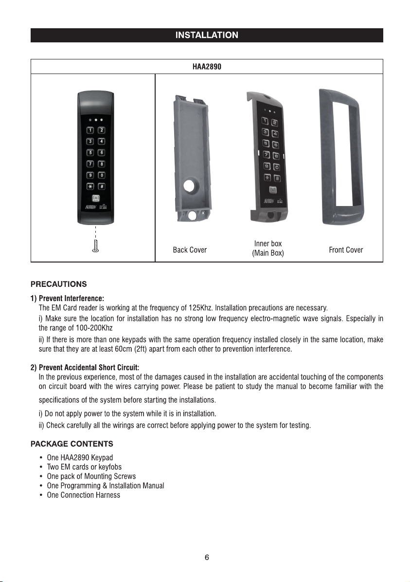
CONNECTION HARNESS
THE WIRE HARNESS
1 - 2 : TAMPER N.C. (Tamper Switch Normally Closed Contact)
A normally closed dry contact while the front cover is secured on the main box. It is open while the cover is
separated from the box. Connect this N.C. terminal to the 24 hour protection zone of an alarm system if necessary.
3 - 4 : DOOR BELL (Output Relay Contact for Door Bell)
It is a Normally Open (N.O.) relay dry contact with maximum rating of 24VDC/1Amp. It is prepared as a triggering
contact of a low voltage door chime. The contact point keeps close as long as the bell button on the keypad is
pressed.
5 - 6 : 12V DC (Power Input Terminal)
Connect to 12V DC power supply. The (-) supply and the (-) GND are the common grounding points of the system.
7 : EG IN ( Egress Input)
A Normally Open (N.O.) input terminal referring to (-) ground. With the help of connecting a normally opened button
to activate Output 1 for door opening in the same manner of using the Group 1 User PINs or Cards.
Egress button is usually put inside the house near the door. More than one egress buttons can be connected in
parallel to this terminal. Leave this terminal open if not used.
See Programming Location 90 for more information about the Egress Button with other features.
8 : GND (-) (Common Ground)
A common grounding point of the keypad
9 : DATA I/O (Data Input/Output Port for Split-Decoded Operation)
A data bus for signal communication with the optional Access Controller in Split-decoded operation.
See "THE APO I/O PORT" Section for the details.
7
Page 8

10 - 11 - 12 : OUTPUT 1 (Output Relay 1)
2 Amp relay dry contact controlled by the Group 1 user PINs or Cards for Output 1, recommended for door strike.
Terminal 10 is Normally Closed (N.C.), terminal 12 is Normally Open (N.O.) and terminal 11 is the common point of
the two contacts. Use N.C. output for Fail-safe locking device; and N.O. output for Fail-secure locking device. The
relay is programmable for Start/Stop (toggle) mode or Momentary timing mode. See programming Location 51 for
the details.
THE ON-BOARD LED INDICATORS
MAINS (AMBER)
DOOR (GREEN) ---INHIBIT (RED) ---------- It lights up while the output is inhibited.
THE PACIFIER TONES & THE LED SIGNALS
The buzzer and the amber LED indicator give following tones and signals respectively for system status:
1) On Programming Mode ----- ON
2) Successful Key Entry 1 Beep 1 Flash
3) Successful Code / Card Entry 2 Beeps 2 Flashes
4) Unsuccessful Code / Card Entry 5 Beeps 5 Flashes
5) Power Up Delay Continuous Beeps Continuous Flashes
6) Output Relay Activation ** 1 Second Long Beep
7) On Standby *** ----- 1 Flash in 1 Second Interval
8) System Refreshing ----- Fast Flashes for 2.5 Minutes
9) Card or PIN Already Stored in System 1 Long Beep -----
NOTE:
* All Pacifier Tones can be ON or OFF through the programming option at Location 71
* * The Output Relay Activation beep can be selected through the programming option at Location 72
* * * The Standby flashing can be ON or OFF through the programming option at Location 73
------
It flashes on Standby. It shows the system status in synchronization with the beep tones.
The standby flashing can be set to OFF in programming. See Location 73 for the details.
---
- It lights up for Output 1 activation.
STATUS TONES * LED SIGNALS
8
Page 9

FEATURE PROGRAMMING & OPERATION INSTRUCTIONS
SET SYSTEM INTO PROGRAMMING MODE WITH THE MASTER CODE
IMPORTANT NOTE:
1) DO NOT TURN OFF POWER while the keypad is in Programming Mode. Otherwise, it may cause data lost/error to the
programmed features in the memory.
2) The keypad beeps after power up. Wait 1 minute until the end of the power up delay, then key in the Master Code for
setting the system into programming mode.
3) For the owner’s convenience in programming at the first time, the factory has put a Master Code 0 0 0 0 into the
keypad (It is NOT a default code). To compromise security, in all cases, the owner should program a new Personal
Master Code to invalidate the factory set Master Code after the keypad is owned.
MASTER CODE VALIDATION
0000
MASTER CODE
The Master Code can be a factory set master code or the private master code that
was set by the owner.
Validate the master code with
2-beep confirms a valid master code. The Mains LED (Amber) is constantly ON after the system is set in the
programming mode.
DIRECT ACCESS TO PROGRAMMING MODE WITH THE “DAP” CODE – 8 0 8 0
* *
.
Set System Into Programming Mode With DAP Code In Case Of The Master Code Is Forgotten ! !
The owner requires to apply the following procedures precisely to set the system into programming mode
with the DAP code 8 0 8 0.
1) Switch OFF all the power for 1 minute to ensure that the system is fully discharged.
2) Swich ON power again. The system is in Power-up Mode for 1 minute and the buzzer gives beeps during the whole
period. This is the only time limit for setting the system to Direct Access to Programming (DAP).
3) Press the Egress Button (EG IN) once first to enable the DAP function.
4) Key in the DAP Code 8 0 8 0 and validate it with
power up beep stops. The keypad turns itself into programming mode like using the Master Code and it is ready to
accept the new programming data.
5) If the Egress Button is not pressed and the DAP code is not keyed in within the power up period, the system will set
itself to normal operation mode. To set it back to power-up mode, repeat procedures 1-4.
EGRESS BUTTON
, the existing Master Code in the memory is erased and the
* *
DAP CODE VALIDATION
8080
DAP CODE
The DAP code is fixed on 8 0 8 0 and it is valid only in the Power-up Period after the Egress Button is pressed.
Validate the DAP code with the
2-beep confirms the system is in the Programming Mode; and the Mains LED is constantly ON.
See “RECORD A MASTER CODE” at “Location 01” for the details of programming a new master code.
PRESS ONCE
* *
.
**
**
NOTE:
If the keypad is linking up with the DA-2800 or DA-2801 controller in the Split-decoded operation, it is necessary to put
the controller’s “Link-up Jumper” to “ON” position to get the new Master Code for it. As the Master Code is also the
link-up code of the two units. Do Not Forget to put the Link-up jumper back to OFF position after the programming.
9
Page 10

REFRESH THE SYSTEM WITH THE “REFRESHING CODE” --- 9 9 9 9
The system can be refreshed to clear all the old data stored and back to its ex-factory default values.
IMPORTANT NOTE:
Make sure that you really want to clear ALL the OLD data before entering of the Refreshing Code. The keypad will be
back with its default values like a new unit. Re-program of the desired values are necessary.
REFRESHING CODE VALIDATION
9999 #
REFRESHING CODE
The Code 9 9 9 9 is for refreshing of the system. Once it is keyed in and validated with #, all the values
programmed previously will be cleared EXCEPT the Master Code.
The refreshing takes around 2.5 minutes. During the keypad is being refreshed the Status LED (Amber) flashes fast
until the end.
THE DEFAULT VALUES OF THE KEYPAD
PROGRAMMING
LOCATION PARAMETERS DEFAULT FUNCTIONS & VALUES
0 1 Master Code 0 0 0 0 Factory Set, Not a default value *
0 2 Super User PINs Nil ----- User Program Required
0 3 Common User PIN 1 Nil ----- User Program Required
1 0 User PINs & Cards for O/P 1 Nil ----- User Program Required
4 0 Visitor Codes Nil ----- User Program Required
5 1 O/P Mode of The O/P 1 Time = 5 Sec, Momentary
6 0 Personal Safety & Lock-out Code = 1, 10 False Code/Card Lock-out 60 Sec
7 0 User Code Entry Mode Code = 2, Manual Entry Mode
7 1 Pacifier Tones ON-OFF Selection Code = 1, Pacifier Tone ON
7 2 O/P Operation Announcer Code = 1 Sec, Notification Beep ON
7 3 Status LED Standby Flashing ON-OFF Code = 1, Flashing Enabled
9 0 Egress Delay & Warning Code 1 = 0, Instant, No Delay
Code 2 = 1, Momentary Contact without Warning
9 4 Operation Modes Code = 0, Stand Alone Keypad
NOTE:
The DAP Code 8 0 8 0 and the Refreshing Code 9 9 9 9 are fixed in the operating system program. It can not be
changed in any ways or be influenced by the system in default setting.
10
Page 11

The HAA2890 has many functions for user’s selection. For those general users taking the keypad for door strike only,
most of the features can be kept in their Default values. Only the User PINs / Cards and a private Master Code are
necessary to program for the system.
The keypad accepts 1) Card only, 2) PIN only, 3) Card + PIN or 4) Card + Common User Code to operate its outputs.
KEYPAD PROGRAMMING MAKE SIMPLE – For General Users
PROGRAMMING
NOTE: Wait 1 minute until the end of the power up delay.
1) Set System into Programming Mode with The Factory Set Master Code 0 0 0 0
0000 **
Note: If the Master Code is forgotten, use the DAP Code to set the system into programming mode. See DAP CODE
8080 on the previous page for the details.
2) Change The Factory Set Master Code to Owner’s Private Master Code for Security Reason
01
3289 is the new Master Code and the 0000 is erased
3) Record an “EM Card” to Operate The Output 1 for Door Open
1
10
(a)
(b) (c) (d) (e)
(a) 10 = Programming Location for Output 1
(b) 1 = Programming option for EM Card only
(c) 001 = One of the 1,000 User IDs for the User PIN/Card from 000-999
(d) Read Card = Put the Card close to the card reader
(e) # = Confirm the card is read, 2 beeps
---- 2 beeps, system is in Programming Mode
3289 #
---- 2 beeps, 3 2 8 9 is a Master Code for example here only
001 #
READ CARD
4) Set an “User PIN” to Operate The Output 1 for Door Open
2
10
(a) (b) (c) (d) (e)
(a) 10 = Programming Location for Output 1
(b) 2 = Programming option for User PIN only
(c) 002 = One of the 1,000 User IDs for the User PIN/Card from 000-999
(d) 8321 = The User PIN that is programmed for door open. 8321 is an User PIN for example here only
(e) # = Confirm the User PIN, 2 beeps
5) Record an “EM Card + User PIN” to Operate The Output 1 for Door Open
10 3 003 6123 #
(a) (b) (c) (d) (e) (f)
(a) 10 = Programming Location for Output 1
(b) 3 = Programming option for EM Card + User PIN. (The User PIN can be repeated use or proprietary)
(c) 003 = One of the 1,000 User IDs for the User PIN/Card from 000-999
(d) Read Card = Put the Card close to the card reader
(e) 6123 = The User PIN to be used with the EM Card. 6123 is an User PIN for example here only.
(f) # = Confirm the Card+PIN is stored, 2 beeps
002 8321 #
READ CARD
11
Page 12

6) Record an “EM Card + Commom User Code” to Operate The Output 1 for Door Open
10 4 004 #
(a) (b) (c) (d) (e)
(a) 10 = Programming Location for Output 1
(b) 4 = Programming option for EM Card + Common User Code
(c) 004 = One of the 1,000 User IDs for the User PIN/Card from 000-999
(d) Read Card = Put the Card close to the card reader
(e) # = Confirm the card is read, 2 beeps, the Common User Code goes to this User ID automatically
(f) A Common User Code (for example: 8 6 2 5) MUST be set at the Programming Location 03 first for this operation
mode. The code can be used for all the EM Cards in this operation mode.
REMARK:
If more User PINs and Cards are required for Output 1, repeat the procedures (3) , (4) , (5) or (6) above with other User
IDs, such as 005, 006, 007 --- 999 etc. Total 1,000 users are allowed. See Programming Location 10 for the details.
7) Close The Programming Mode
---- 2 beeps
**
The programming mode is closed. The keypad is back to normal operation mode
READ CARD
OPERATION
8) Open The Door with The EM CARD
---- 2 beeps, the door is open
READ CARD
9) Open The Door with The User PIN
8321 #
10) Open The Door with The EM CARD + User PIN
READ CARD
---- 2 beeps, the door is open
6123 #
---- 2 beeps, the door is open
11) Open The Door with The EM CARD + Common User Code
READ CARD
REMARK:
In the next Section, “KEY IN AND STORE THE DESIRED VALUES” describes all the features and functions of the system
in detail. Users can follow them to tailor the desired values for their access control systems. Suggest the general users
also spend some time on them to get acquaint with this powerful system for future expansion.
8625 #
---- 2 beeps, the door is open
12
Page 13

FEATURE PROGRAMMING -- KEY IN AND STORE THE DESIRED VALUES
The feature values can be set and stored into the system one by one with the desired Programming Locations.
Programming can be made continuously and it is not necessary to be in sequence order. Just go to the desired
programming location and key in the value for the desired feature.
IMPORTANT NOTE --- Programming Criteria for Codes:
a) The Prime Codes:
All the Private User PINs, Master Code, Duress Codes, Super User PIN, Common User Code and the Visitor User Codes
belong to Prime Codes in the system. They have the priority to be read and they MUST be unique and can not be
repeated in the programming. A Prime code also can NOT be duplicated for a Secondary code to work with the EM Card
or vice versa.
b) The Prime Cards:
All the EM Cards used in this system are Prime Cards. The cards MUST be unique and can not be repeated use. The
Card always has the priority to be read when working with an User PIN in “EM Card + Secondary PIN” or EM Card +
Common User PIN”.
c)Warning for A Repeated Use of Prime Code or Card:
One long beep is given if a Code/PIN is keyed in or a Card is read. It means that a Prime Code or a Prime Card is
repeated. The Code/PIN or Card was already in one of the PIN or Card Locations or IDs. The programming is invalid.
Change a new Code/PIN or Card and program it again.
d)Secondary User PINs:
The Secondary User PINs are prepared to enhance security. It is put after a Card in “EM Card + Secondary User PIN”
programming. They can be a repeated code within the Secondary PINs but it is NOT allowed a duplicate of the Prime
Codes. The system will reject a duplicated Prime Code for Secondary User PIN or vice versa.
e)Getting Advantages from The Secondary User PINs:
The repeated Secondary PINs can be used as a Group Common User Code or called Department User Code for a group
of EM Cards, which simplifies the programming of using large number of different User PINs. EM Card with Department
Code prevents a lost card used by people of other department. Also, it will be easier to trace out the depar tment of the
lost card belongs to. Of cause, the owner can use a proprietary Secondary User PIN for each EM Card in the “EM Card
+ Secondary User PIN” programming to further increase the security if it is the main concern.
f) Security Level Comparison of The Secondary User PIN/Code following Card Reading:
i) EM Card + Common User Code --- All EM Cards use the same User Code. Security level is better than just Card
only. A lost Card picked up by any people can be used if he knows the Common User Code.
ii) EM Card + Department User Code --- The EM Cards are divided into groups with a Depar tment User Code. A lost
Card can be used only by the people in the same group who know the Department Code.
iii) EM Card + Secondary User PIN --- Each EM Card has its own proprietary User PIN. A lost Card can not be used
by other people.
g) Make A List Recording of The User Names VS User Codes:
Suggest the owner to make a list recording of the User Names corresponding to the Codes/PINs/Cards that are going to
store in the Locations and the IDs before the programming. It will be a useful tool for the owner to easily program them
smoothly and also to trace them from this multi-users system in the future.
Example: (Please see the following page)
13
Page 14

Example:
User Name Location Function Code User ID PIN/Code Card # Remark
1
2
3
4
5
6
7
8
9
10
11
12
13
14
15
16
-1,000
RECORD A MASTER CODE (Location 01)
MASTER CODE VALIDATIONLOCATION
01
4 to 8 Digits
#
MASTER CODE
Master Code is the authorization code for setting the system to programming mode. It is NOT an User Code
operating of the output relays.
The Master Code can be 4 to 8 digits. Press # key to confirm code entry
When a new master code is keyed in and confirmed, the old master code is replaced automatically.
The master code is also the Link-up Code between the keypad and the optional controller of the system in Splitdecoded operation.
Example: Set a Master Code with the number of “2 2 3 3” ----
RECORD A SUPER USER PIN (Location 02)
The Super User PIN has TWO functions. It is prepared for the owner to use it to operate the keypad under inhibit
condition and make operation of inhibit enable / disable to the system output.
02
SUPER USER PIN
The Super User PIN can be 4 to 8 digits.
Two beeps will be heard after pressing the # key to confirm code entry.
When a new Super User PIN is keyed in and confirmed, the old one is replaced.
Example: Set a Super User PIN with the number of “2 5 8 0” ---To deleted a Super User PIN from memory: Key in just the Location number and #. ----
14
01
2233 #
SUPER USER PIN VALIDATIONLOCATION
4 to 8 Digits
02 2580 #
02
#
#
Page 15

OPERATION AND FUNCTIONS OF THE SUPER USER PIN
1) Operate Output 1 (Output Relay 1)
The operation of the Super User PIN is just like a normal User PIN. Simply key-in the PIN with a specific output
number for the Output. The Super User PIN can also be used to reset an operating output timer instantly.
---------- Output 1 Activates or Resets
SUPER USER PIN
2) Inhibit The User PINs For Output 1
The Super User PIN can also be used to inhibit the normal User PINs/Cards for the Output 1 (usually they are for
door strike). It enhances the security level of the access control system, such as to stop a keypad after office hour
or while the house is nobody inside. Once the Output 1 is inhibited, the User PINs/Cards for it become invalid and
those people even know the User PINs are refused during the system is inhibited. The inhibit function is toggled in
Start / Stop mode with the following code entry.
---------- The Whole Group of User PINs & Cards for Output 1 are Disabled
SUPER USER PIN
NOTE:
The inhibit function setting with the Super User PIN applies to the whole group of User PINs and Cards for
Output 1.
For safety reason, the inhibit function initiated with the Super User PIN does not govern the Egress Button. The
door still can be opened with it from inside.
The function of the Super User PIN is not affected in the Inhibited Mode or Lock-out Mode. It is always a normal
user code for Output 1.
# 1
9
#
or Enabled in Toggle
RECORD THE COMMON USER PINS FOR OUTPUT 1 (Location 03)
The Common User PIN is prepared for operating of the Output 1 as an enhance code. The Common User PINs MUST
work in the form of “Card + Common PIN” to operate the outputs to increase the security of the access control
system. See Location 10 for more information.
NOTE : Common User PIN alone can NOT be used to operate Output 1 directly.
COMMON USER PIN VALIDATIONLOCATION
03
COMMON USER PIN LOCATION
-- Location Stores The Common User PIN for Output 1
03
COMMON USER PINS
The Common User PIN can be 4 to 8 digits. Press # key to confirm the code entry.
When a new Common User PIN is keyed in and confirmed, the old one is replaced.
Example: Set a Common User PIN with the number of “1 3 5 7” for Output 1 ----
To deleted a Common User PIN from memory: Key in just the Location number and #. ----
15
4 to 8 Digits
03 1357 #
03
#
#
Page 16

RECORD-DELETE PINS OR CARDS FOR OUTPUT 1 (Location 10)
Total of 1,000 User PINs and/or Cards are available for controlling of the output relay 1.
The Private User PINs and Cards MUST be unique. Repeated PINs will be rejected. Secondary User PINs in the “EM
Card + Secondary User PIN” can be repeated. See the Important Note --- Programming Criteria for Codes in page 13
for more information.
CARD &/OR USER PIN VALIDATIONLOCATION MEDIA USER ID
10 1-5 000-999 #
USER GROUP LOCATION
– Group 1 --For User PINs/Cards Controlling Output 1
10
1,000 Users are allowed in group 1 for O/P 1
SELECTION OF OPERATION MEDIA
Number 1, 2, 3 or 4 represents the Media to be used to operate the keypad.
Number 5 is the authorization code for deleting of an PIN and/or Card from
its User ID.
= EM Card only; = Private User PIN only;
1 2
= EM Card + Secondary User PIN = EM Card + Common User PIN
3 4
= Delete an User PIN &/or Card from the selected User ID number
5
CARD &/OR USER PIN
0999
USER ID NUMBER
A 3-digit ID is an identified number for each User PIN and/or Card.
Repeated ID number will be rejected by the system
ID Number
CARD &/OR USER PINS
The User PINs can be 4-8 digits. Key in the User PIN on each ID Number box, then confirm it with # key
Just simply put the EM card close to the reader window to read it on each ID Number box, then, confirm it with
# key if it is a Card ONLY, or Card + Common User PIN entry. The Common User PIN is NOT required to key-in
here. It will go into its location automatically after the Card is read.
Read the Card first, then key in the Secondary User PIN on each ID Number box, then confirm it with # key if it
is Card + Secondary User PIN. The Secondary User PINs can be duplicated or a proprietary User PIN but can
not be a duplicate of a Prime Code. Owner can use the same secondary User PIN for a group of Cards as a group
Common User Code (or called Department Code) for a specific relay output.
Cards (Operation Media # 1, 3, & 4) and Private User PINs (Operation Media 2) MUST be unique. A repeated EM
card or Private User PIN will be rejected and one long beep will be generated by the system to notify the owner.
= Clear all the PINs & Cards from the selected Location. It takes
few seconds to a minute to complete depending on the Location
selected and the data stored.Please see the programming example
below for the details.
000
-
999
for 1,000 User PINs/Cards to operate Output 1
16
Page 17

EXAMPLES – PROGRAMMING AND OPERATION
1) Example 1 -- EM Card Only :
i) Programming :
Read Card
10 1 001
(a) (b)
(a) The card is programmed for operating of the Output 1
(b) The operation is EM Card only
(c) Take ID number 001 in Group 1 to store the card, which is one of the IDs in 000-999
(d) Put the card close to the reader to read it, one beep confirms the reading
(e) Press # to store the “Card” into memory, two-beep confirms a valid entry
ii) Operation : (while the system is back to operation mode)
Read Card
(a)
a)Put the EM card close to the reader. Two-beep confirms the card is read and the Output 1 activates
2) Example 2 -- Private User PIN Only :
i) Programming :
10 2 002 1234 #
(a)
(a) The Private User PIN is programmed for operating of the Output 1
(b) The operation is Private User PIN only
(c) Take ID number 002 in Group 1 to store the Private User PIN, which is one of the IDs in 000-999
(d) Put Private User PIN “1 2 3 4” into the storage location
(e) Press # to confirm and store the “Private User PIN” into memory, two-beep confirms a valid entry
ii)Operation : (while the system is back to operation mode)
(a) (b)
(a) Key in the Private User PIN “1 2 3 4”
(b) Confirm it with the # key. Output 1 activates
(b) (c) (d) (e)
1234 #
(c) (d) (e)
#
3) Example 3 -- EM Card + Secondary User PIN :
i) Programming :
10 3 003 24680 #
(a) (b) (c) (d) (e) (f)
(a) The card is programmed for operating of the Output 1
(b) The operation is EM Card + Secondary User PIN
(c) Take the ID number 003 in Group 1 to store the Card & PIN, which is one of the IDs in 000-999
(d) Put the card close to the reader. One beep confirms the reading
(e) Put Secondary User PIN “2 4 6 8 0” into the storage location
(f) Press # to store the “Card + Secondary User PIN” into memory, two-beep confirms a valid entry
ii) Operation : (while the system is back to operation mode)
Read Card
24680 #
(a) (b) (c)
(a) Put the EM card close to the reader. Two-beep confirms the reading and 30 seconds waiting time is given for the
entry of the User PIN, the Amber LED keeps flashing
(b) Key in the Secondary User PIN “2 4 6 8 0”
(c) Confirm it with the # key. Output 1 activates
Read Card
17
Page 18

4) Example 4 -- EM Card + Common User PIN :
i) Programming :
10 4 004 #
(a) (b) (c) (d) (e)
(a) The card is programmed for operating of the Output 1
(b) The operation is “EM Card + Common User PIN”
(c) Take ID number 004 in Group 1 to store the card, which is one of the IDs in 000-999
(d) Put the card close to the reader. One beep confirms the reading. (No need to key in a Common User PIN but
there MUST be a Common User PIN already recorded in Location 03;
(e) Press # to store the “Card” into memory. Two-beep confirms a valid entry
ii) Operation : (while the system is back to operation mode)
Read Card
#
(a) (b) (c)
a) Put the EM card close to the reader. One-beep confirms the reading and 30 seconds waiting time is given for the
entry of the Common User PIN, the Amber LED keeps flashing
b) Key in the Common User PIN “1 3 5 7” (the number programmed in “Location 0 3” for Output 1 in the previous
Example)
c) Confirm it with the # key. Output 1 activates
5) Example 5 -- Delete an User PIN & / or EM Card :
i) Delete An User PIN or A Lost EM Card
10 5 #
(a) (b) (c) (d)
a) Key in the User Group that the User ID belongs to. “10” for the Group 1. This keypad has user Group 1 only
b) Key in “5” that is the Command Code for making a deletion here
c) Key in the User ID that stored the User PIN, the lost EM card or the EM Card+User PIN
d) Press the # key. Two-beep confirms a valid entry and the PIN and/or Card in that User ID is cleared
Common User PIN
User ID
Read Card
ii) Delete an EM Card
10 5 #
(a) (b) (c) (d)
a) Key in the User Group that the EM Card belongs to. “1 0” for the Group 1. This keypad has user Group 1 only
b) Key in “5” that is the Command Code for making a deletion here
c) Put the EM card close to the reader. One-beep confirms the reading. Read the Card only also makes a valid
deletion to the Card working with the Common User PIN or the Secondary User PIN
d) Press the # key. Two-beep confirms a valid entry. The EM Card in that User ID is cleared. Key in the User ID is not required.
6) Example 6 – Clear The Whole Group of Users :
Whole group of users including the PINs and Cards can be cleared with the following command.
Read Card
10 0999 #
(a) (b) (c)
a) The User Group 1 – “10” is selected to be cleared. This keypad has user Group 1 only
b) Key in the Group Deletion Command, 0 9 9 9
c) Confirm the deletion with #. All the User PINs and Cards in the Group 1 are cleared. It takes few seconds to
a minute to complete depending on the data stored.
18
Page 19

VISITOR CODES (FOR OUTPUT 1 ONLY) (Location 40)
The Visitor Codes are the temporary user codes for operating of the Output 1 (mainly for door strike in access control).
They can be programmed as “One Time Codes” or “Codes with Time Limit”. The Visitor Codes will be cleared
automatically after use if they are one time codes, or, when the allowed time expires.
VISITOR CODE VALIDATIONLOCATION VISITOR ID VALID PERIOD
40 #
VISITOR ID
50 Visitor IDs for storing the codes. They are represented by a
Two-digit ID Number of
0999
VALID PERIOD
The codes in this box MUST be two digits and they represent the time of the operation.
--- One Time Code
00
One Time Code has no time limit but it can only be used for ONCE.
It is cleared by the system automatically after use.
01-99
The Visitor Code can be set with the valid time limit of 1 Hour to 99 Hours with a
two-digit number of 01 to 99. The visitor code is cleared by the system when
the time limit reaches.
VISITOR CODES
When a new Visitor Code is put in the same Code box, the old code is replaced.
The Visitor Codes can be 4-8 digits for the Manual Mode code entry.
The Visitor Codes MUST be in the same digit length with the Master Code for Auto Mode code entry.
NOTE: All Visitor Codes will be cleared after power down to prevent extension/confusion of their valid time limit.
EXAMPLES:
Example 1: Set a “One Time Visitor Code” with the number of “1 2 6 8” for the Output 1
01
= Clear all the Visitor Codes from Location 40. Please
see the Programming example below for the details.
--- Time Limit in Hour(s)
01
to
50
-
50
.
00
or
01-99
4-8 DIGITS
(a) (b) (c) (d) (e)
(a) Visitor Code Programming, (b) The Visitor ID, (c) An One Time Code, (d) The Visitor Code, (e) Entry Confirmation
Example 2: Set a “Visitor Code” with the number of “1 3 7 8” that is valid for three hours for the Output 1
(a) (b) (c) (d) (e)
(a) Visitor Code Programming, (b) The Visitor ID, (c) Valid for 3 Hours, (d) The Visitor Code, (e) Entry Confirmation
Example 3: Delete a “Visitor Code” from Vistor ID
(a) (b) (c)
(a) Visitor Code Programming, (b) The Visitor ID, (c) Delete Confirmation
Example 4: Clear all “Visitor Codes” from Location
(a) (b) (c)
(a) Visitor Code Location, (b) The Deletion Command Code, (c) Confirmation, all Visitor Codes are cleared
40 01 00 1268 #
40 02 03 1378 #
in the memory
02
40 02 #
40
40
0999 #
19
Page 20

CONFIGURATION OF THE OUTPUT MODES OF OUTPUT 1 (Location 51)
The relay output of this keypad is programmable for Start/Stop or Timing modes. Apar t from the door access control,
alarm arm-disarm control, it is also an universal timer for automatic operator in industry with its 99,999 seconds (over
24 hours) programmable timer.
OUTPUT MODE & TIME VALIDATIONLOCATION
51 0
OUTPUT LOCATION
-- Location for Output 1
51
OUTPUT MODE & TIMING
– Start /Stop Mode (Toggle)
0
The number 0 sets the output to the Start / Stop mode. The output Starts when an User PIN and/or Card is entered/
read; the output Stops when an User PIN and/or Card is entered/read again.
or 1-
99999 #
1-99999
The output can be set in Momentary Mode with the time of 1 second to 99,999 seconds. The output will reset
automatically when the time expires OR it can be RESET manually at anytime with the Super User Code before the
end of the time.
Example : Reset Output 1 --
PERSONAL SAFETY AND SYSTEM LOCK-OUT (Location 60)
SAFETY & LOCK-OUT OPTIONS
The Options are represented by their Mode Numbers in programming. They are described below:
--- After 10 successive false Card/User Code trials, the keypad locks during 60 seconds. -- (Default)
1
-
5
10
--- Disappearance of all the above lock-out securities.
00
Seconds Momentary --- (Default -- Momentary 5 Seconds)
SUPER USER CODE
--- Selection of after 5 to 10 successive Card/User Code trials, the keypad locks during 15 minutes.
The keypad can be reset to release the lock-out with the “Super User Code” in the following way.
Example : Release the lock-out --
# 1
SUPER USER CODE
------------- Output 1 resets
LOCK-OUT MODES VALIDATIONLOCATION
60 #
1 to 2 Digits
# 9
20
Page 21

USER PIN ENTRY MODE – Auto or Manual (Location 70)
ENTRY MODES VALIDATIONLOCATION
or
1
270 #
USER PIN ENTRY MODES
Two modes 1 and 2 are available for User PIN entry options. The EM Card is always in Auto Entry Mode and is not
affected by the selection here.
--- Auto Entry Mode
1
Auto Entry Mode requires no pressing of the
In the Auto Entry Mode, the User PINs MUST be set in the same digit length of the Master Code (For example, if
the Master Code is 5 digits, then all User PINs must be in 5 digits as well. All other User PINs not in 5 digits become
invalid). When the number of digits reaches, the system will check the User PIN automatically. Good for high traffic
access control.
--- Manual Entry Mode – (Default)
2
Manual Entry Mode always requires the
digits arbitrary and they are NOT required to be in the same digit length of the Master Code. Manual Entry increases
the level of security in the code trial by the unauthorized people.
PACIFIER TONES ON-OFF SELECTION (Location 71)
#
key following the User PIN for code checking.
#
key following of the User PIN for code checking. The User PINs can be 4-8
FUNCTION MODES VALIDATIONLOCATION
or
1
0 #71
PACIFIER TONES ON-OFF MODES
The Pacifier Tone is the Beep Tones from the keypad, which include the tones of Successful Key entry (1 beep), the
Output Operation Announcer (2 beeps or 1 long beep) and the Unsuccessful User Code/Card entry (5 beeps).
NOTE :
The beeps for the Warning and the Power-up Delay do not belong to pacifier tones and can not be set to OFF.
--- Pacifier Tone ON – (Default)
1
All the Pacifier Tones available from the keypad are enabled. They are the response tones indicating the operation
status of the keypad after the Card/User Code is entered.
--- Pacifier Tone OFF
0
All the Pacifier Tones are OFF. Good for place needs for a silent environment.
21
Page 22

OUTPUT OPERATION ANNOUNCER (Location 72)
FUNCTION MODES VALIDATIONLOCATION
or
1
0 #72
OUTPUT OPERATION ANNOUNCER
The announcer gives notification beep to the users and the visitors on the operation status of the outputs. There are
two notification modes available for the selection. The notification is also OFF while the Pacifier Tone OFF mode in the
Location 71 is selected.
--- 1 Second Long Notification -- (Default)
1
1 second notification beep is given when the output relay is activated with a valid Card/Code or Egress Button. It is
prepared to notify the person outside the door when the lock is released and the door can be opened. It is good for
the door lock device gives no sound when it activates, such as a magnetic lock.
--- 2 Short Beeps Notification
0
2 short beeps notification is given when the output is activated with a valid Card/Code.
STATUS LED FLASHING ON-OFF DURING STANDBY (Location 73)
FUNCTION MODES VALIDATIONLOCATION
or
1
0 #73
STANDBY FLASHING ON-OFF
Some people find the flashing light of the status LED (the amber LED) is annoying during the keypad is on standby,
especially at the night time. The standby flashing can be ON-OFF with the setting here.
--- Standby Flashing ON -- (Default)
1
The Status LED gives Standby Flashing all the time during the keypad is on standby. It also gives all the light
indications showing the operation status of the system.
--- Standby Flashing OFF
0
The Standby Flashing is disabled but it does not affect the system status indications. All the light indications from it
are unchanged.
22
Page 23

INTELLIGENT EGRESS BUTTON – AN UNIQUE FEATURE OF A CONTEMPORARY KEYPAD
Most of the keypads for access control are just for controlling of “Going In” from outside. It is not enough for today’s
access control systems. In fact, controlling of “Going Out” is also very important in many public passage areas. They
are not allowed to use locks or digital keypads for stopping of “Going Out” due to safety reasons. Such as hospitals,
kindergartens, elderly homes, convenient stores, emergency exits etc.. The wardens, teachers, shopkeepers and the
guards are always required to keep an eye on people to prevent unattended leaving, shoplifting, and illegal use of the
emergency exits.
The Intelligent Egress Button can be programmed to do something to get the attention of the person on duty before the
door is opened. The button offers programmable egress delay, delay with warning, holding button required for the delay,
momentary button contact with warning for the delay.
Location 90 is the place for setting the desired functions for the Egress Button.
The functions programmed to the Egress Button do not affect the normal operation of the system with its keypad. For
the safety consideration, the operation of the keypad with PIN, Code or Card is always in the first priority to give instant
action to the output relay 1 for door strike.
It is NOT required to program the Egress Button with the special function in normal use. Just leave it on its default
values.
WHERE AND WHY “GOING OUT” NEEDS ATTENTION
Examples for some areas may need an Intelligent Egress Button:
Hospital:
Some of the patients are not allowed to leave the ward without doctor’s permission. An egress button with exit delay
and warning beeps will help the nurse or warden to get the attention to the door when the egress button is pressed.
Further setting of the egress button with holding contact for the delay even gives higher level of security to a controlled
door.
Kindergarten:
Young children are always active. Some of them may be willing to go out to explore their ways of playing. For safety
reason, teachers have to watch all of them in the attended area. Leaving school alone without the companion of parents
or teacher is dangerous to the young children. An egress button with delay and warning beeps will be helpful to prevent
the children trying to go out without getting the attention of the teacher.
Elderly Home:
Elderly needs constant attention and care. Some old people have poor memory. They may forget the way to come
back if they leave home alone. An egress button with delay and warning beep will easily get the attention of the warden
before the door is open.
Convenient Store:
Most of the convenient stores have just only one or two shopkeepers on duty. They are usually the cashier. Shoplifting
may easily happen while the shopkeeper is busily serving customers at the cashier desk. A holding contact egress
button with delay and warning beeps may help to stop most of the shoplifting. As the thief knows that he is gotten
attention by the shopkeeper before the door is open.
High Traffic Passage:
A short buffer time may be necessary for opening a door outward after pressing the egress button for those exits open
to a high traffic passage. An egress button with short delay and warning beeps helps the user to pay attention to the
people passing by to prevent hitting them when the door is pushed outward.
Emergency Exit:
Emergency Exit is not open to the public for daily use. It is for emergency case only. It is usually closed and watched by
the security guards. The egress button of this keypad can be programmed to offer exit delay with warning beeps when
the door is forced to open or the door is open after the exit delay expired. It is an useful tool to get the attention of the
person on duty.
23
Page 24

EGRESS DELAY AND WARNING (Location 90)
FUNCTION MODES VALIDATIONDELAY TIMELOCATION
, 2 , 4 or
1
CONFIGURATIONS OF THE EGRESS WARNING AND ALARM
Key in the number to enable 1, 2, 4 or 5 configurations described below:
--- Momentary Contact Mode without Warning -- (Default)
1
•Press the Button once. No warning or alarm is given during Egress Delay.
•Good for silent area. The people have to wait for the door open until the delay time
reaches.
--- Momentary Contact Mode with Warning Beep
2
•Press the Button once. The system gives Warning Beeps during the Egress Delay.
•Good for the place required attention. The keypad beeps during the people are waiting for
the door open.
--- Holding Contact Mode without Warning
4
•Press and hold the Button. No warning or alarm is given during the Egress Delay.
•Good for the silent area. The people require to press & hold the button until the delay time
reaches for the door open.
--- Holding Contact Mode with Warning Beep
5
•Press and hold the Button. The system gives Warning Beeps during Egress Delay.
•Good for the place required attention. The keypad beeps while the button is kept pressed
during the people are waiting for the door open.
EGRESS DELAY TIMER
--- No Delay – (Default)
0
Output 1 activates instantly (the door is released instantly) when the Egress Button is pressed.
5 0
or 1 -
99 #90
–
1
Put any number of 1 to 99 into the box to enable the Egress Delay. The number is the time in second, which starts to
count when the Egress Button is pressed. Output 1 activates (the door is released) when the delay time reaches.
NOTE:
1) Momentary Contact -- The Egress Delay starts to count when the egress button is momentarily pressed. Output 1
activates automatically (door is released) when the delay time reaches.
2) Holding Contact -- The user MUST hold the egress button in contact for the whole period of the Egress Delay time
until Output 1 activates. If the egress button is released before the end of the Egress Delay, the timer will stop to count
and reset.
3) The Egress Delay does not affect the operation of the User PINs/Cards for Output 1. The User PINs/Cards always
give INSTANT action.
EXAMPLES:
Example 1: Set Egress Button in Momentary contact 5 seconds with delay & warning beep
(a) (b) (c) (d)
(a) Egress function programming, (b) Momentary contact with warning, (c) Delay time of 5 seconds to release door,
(d) Entry confirmation
--- Egress Delay Timing
99
90 2 5 #
24
Page 25

Example 2: Set Egress Button in Holding contact of 10 seconds with warning beep
(a) (b) (c) (d)
(a) Egress function programming, (b) Holding contact mode with warning, (c) Holding time of 10 seconds to release
door, (d) Entry confirmation
Example 3: Set Egress Button in Momentary contact without delay (This is the default setting)
(a) (b) (c) (d)
(a) Egress function programming, (b) Momentary contact without delay, (c) Release door instantly, (d) Entry
confirmation
90 5 10 #
90 1 0 #
CLOSE THE PROGRAMMING MODE (
Always close programming mode with
VALIDATION
------------------------------- System is back to normal operation mode
**
to set system back to normal Operation after programming.
* *
* *
)
25
Page 26

THE OPERATION MODES (Location 94)
Four operation modes are available for the selection. The codes are 0, 1, 2 and 3.
OPERATION MODELOCATION VALIDATION
, 1 , 2 or
WIEGAND OUTPUT AT KEYPAD OPERATION MODE
0 --- Stand Alone Keypad Mode -- (Default)
The system provides full functions to operate its outputs.
1 --- Card & Code Reader Mode (Not Available in this model)
2 --- Master Keypad of Split-Decoded Mode
The Master keypad will transfer all the programmed feature data (except the user PINs, Codes and Cards data) to the
Access Controller (decoder) right after it exits the programming mode. A Split-decoded keypad system needs at least
one Master keypad and one Access Controller to work.
3 --- Slave Keypad of Split-Decoded Mode
No feature data is transferred to the Access Controller (decoder) from the Slave keypad. It takes the same feature
data from the Master keypad to operate. The Slave keypad(s) is for a Split-Decoded system that needs more than one
keypads for operation convenience.
NOTE:
a) Do not set more than one keypads in Master mode in a Split-Decoded system. Otherwise, the data will be confused.
b) Each keypad in Split-Decoded mode can be programmed independently with its own user PINs, Codes and Cards.
The PINs, Codes and Cards can be repeatedly used in other keypads in the same system.
394
#0
26
Page 27

THE APO DATA I/O PORT -- FOR SETTING UP A SPLIT-DECODED KEYPAD
The information here is for setting up the keypad unit with an optional “Digital Keypad Access Controller DA-2800” to
make up a high security Split-decoded Keypad system only. It is NOT required for the keypad in Stand Alone operation.
Split-decoded Keypad System
Most of the general purpose keypads on the market are self-contained systems for stand alone operation. It controls the
appliance(s) directly with its output relay contact(s); such as the electric lock in an access control system. The electric
lock is connected to the keypad that is installed outside the house. The thief can open the door without a code or card
but just open the keypad box and make contact to the output relay terminal. It is a safety drawback in security.
The high security systems are usually operating in the Split-decoded mode that combines an outside unit for card
reading and code entry; and a control panel or a decoder unit installing in a secure closet inside the house. The outside
unit and the inside unit communicate in digital data with each other. All the commands are in digital codes, the thief can
do nothing to the inside unit even the outside unit is opened in sabotage. This design philosophy confirms high security
to the area protected, but not just relying on the protection of the keypad with the outer box and two screws.
The keypad unit comes with a data I/O (data input and output) port for the connection with the APO’s Access Controller
DA-2800 for Split-decoded operation to up-grade its security level. Once the keypad unit is connected with the
controller, all the commands from it will be faithfully decoded by the decoder. The input & output control functions
available from the keypad are now all transferred to the controller. The keypad’s role is just a card reader and/or a
keyboard for code entry. The link up of the two units is very simple. It is just one wire (The White Wire) for the I/O ports
and a common grounding wire (The Black Wire) for the two units. The I/O port provides the data in the proprietary APO
format. It ONLY works with the DA-2800.
The Optional DA-2800 Controller --- Introduction
The DA-2800 controller unit is compatible with the keypad unit. Maximum 3 keypads can be connected in parallel to it.
It decodes the data faithfully from the keypads even each of them have different settings of their own. The only criterion
for multi-keypad link-up is all the keypads are set with the same Master Code and is read by the controller while it is in
the link-up mode.
Apart from the decoding function to follow the features from the keypad(s), the DA-2800 is also an independent
4-channel RF remote controller to operate its 3 output relays and the built-in door chime. The DA-2800 is an ideal
device working independently in the RF remote control areas, such as door lock strike in access control, garage door
opening control, alarm arm-disarming control and automatic operator control etc.
The keypad unit is up graded to a Tri-Tech system after in connection with the DA-2800 controller. The system accepts
EM Cards, User PINs and the RF Remote Keys in access control.
RF WIRELESS
REMOTE CONTROL
DATA I/O
DOOR LOCK
COMMON
DK-2890
GROUND
DK-2890
DATA I/O
COMMON GROUND
MAXIMUM 3 KEYPADS CAN BE
CONNECTED IN PARALLEL
DA-2800 ACCESS CONTROLLER
DA-2800 OR DA-2801
CONTROLLER
EXIT
HAA2890 IN SPLIT-DECODED OPERATION
GARAGE
DOOR OPENER
SECURITY SYSTEM
OR
AUTOMATIC
OPERATOR
The User Manual of the DA-2800 provides the operation details of the system on decoding controller mode and
independent operation mode. Please contact your local agent if purchase of the DA-2800 Controller is required.
REMARK: DA-2801 is the simplified version of the DA-2800 without wireless remote control funtion.
27
Page 28

PROGRAMMING SUMMARY CHART
LOCATION
0 1
0 2
0 3
1 0
4 0
5 1
6 0
7 0
7 1
7 2
7 3
9 0
FUNCTION
Master Code 4-8 Digits
Super User PIN 4-8 Digits
Common User PIN for O/P 1 4-8 Digits
User PINs / Cards for O/P 1
Visitor Codes
O/P Mode for O/P 1
Personal Safety & Lock-out
PIN Entry Mode
Pacifier Tone ON-OFF
Output Announcer
Standby LED Flashing
Egress Delay Warning
ENTRY LIMITS & CODE
CODE 1
1---EM Card
2---Private User PIN
3---EM Card+Sec User PIN
4---EM Card+Com User PIN
5---Deletion of User PIN
CODE 2
000-999---Group 1
CODE 3
4-8 Digits / Cards
CODE 1
CODE 2 - VALID PERIOD:
00---One Time
01-99 Hours
CODE 3
4-8 Digits
OUTPUT MODE & TIME:
0--- Start / Stop
1---99999 Seconds,
Momentary
LOCK-OUT CODE:
1---10 Trial, Lock-out 60 Sec.
5-10---5-10 Trial, Lock-Out 15
Minutes
00---No Lock-out
ENTRY MODE:
1---Auto Mode
2---Manual Mode
FUNCTION MODE:
0---OFF
1---ON
CODE 1 - FUNCTION MODE:
1---Momentary, No warning
2---Momentary, with warning
4---Hold Contact, No warning
5---Hold Contact, with warning
CODE 2 - DELAY TIME:
0---No Delay
1-99 Seconds
OPTIONS
-
MEDIA:
-
USER ID:
-
USER PINs / Cards:
-
VISITOR ID: 01-50
-
VISITOR CODE:
MASTER CODE
01
SUPER USER PIN
02
COMMON USER PIN 1
03
CODE1 CODE2 CODE3
10
CODE1 CODE2 CODE3
40
O/P MODE & TIME
51
LOCK-OUT CODE
60
ENTRY MODE
70
FUNCTION MODE
71
FUNCTION MODE
72
FUNCTION MODE
73
CODE 1 CODE 2
90
CODE ENTRY
#
#
#
#
#
#
#
#
#
#
NIL
NIL
NIL
NIL
#
NIL
#
5 Seconds
Code = 1,
10 Trials,
Lock-out 60
Seconds
Mode = 2,
Manual Mode
Mode = 1,
Pacifier Tone
ON
Mode = 1
Announcer ON
Mode = 1,
Flashing On
Mode = 1
Momentary,
No warning
TIME = 0
No Delay
FACTORY
DEFAULT
28
Page 29

9 4
Operation Mode
OPERATION MODES
0---Stand Alone Keypad
Codes & Cards Only
-
1---Reader
2---Master Keypad
& Cards only
3---Slave Keypad
& Cards only
-
Valid
All Codes & Cards
-
Valid Codes
-
Valid Codes
94
OPERATION MODE
#
SYSTEM CODES FUNCTION CODE ENTRY RESULTS
Factory Set Master Code
for User to set system in
0 0 0 0
9 9 9 9
8 0 8 0
0 9 9 9
* *
programming Mode at the
first time.
THIS IS NOT A PERMANENT
SYSTEM CODE & IT IS
CHANGED IF A NEW MASTER
CODE IS PROGRAMMED.
REFRESH CODE -- Refresh
the system and set all its
function back to default
values.
DAP CODE-- Direct access
to programming mode. Valid
only in the power-up delay
period
USER PINs / Codes / Cards
whole group clearance Code
-
Key in the Code to clear all
the users in the Location
LOCATIONS:
10--- User Group 1
40--- Vistor Group
Exit Programming Code
0000 * *
OR
NEW MASTER CODE
* *
9999 #
8080 #
LOCATION NO.
0999 #
**
System in Programming Mode
All programmed data are cleared and
back to the default values except the
Master Code
System in Programming Mode
Whole group of users in the selected
location are cleared
The system back to normal opration
after programming
Mode = 0
Keypad Mode
29
Page 30

ELECTRIC LOCK
APPLICATION EXAMPLE
BASIC WIRINGS OF A STAND ALONE DOOR LOCK
THE WIRE HARNESS
12V DC
POWER
SUPPLY
AD-1312
OR
AP-960
1N4004
OUTPUT RELA
N.O. Output for
Fail-secure Loc
N.C. Output for
Fail-safe Lock
CATHODE
MORE EGRESS
BUTTONS CAN
BE CONNECTED
IN PARALLEL
EGRESS
BUTTON
Y
k
N.O. N.C.
OR
N.O.
N.O.
NOTE:
Connect the 1N4004 as close as possible to the lock in parallel with the lock power terminals of the lock to absorb
the back EMF to prevent it from damaging the keypad. The 1N4004 is not required if the electric lock is AC operated.
To avoid Electro-Static-Discharge from interfering with the operation of the keypad, always ground the (-) terminal
of the keypad to earth.
30
Page 31

PURPLE
APPLICATION HINTS FOR THE AUXILIARY TERMINALS
(A) TAMPER N.C.
The tamper switch is Normally Closed while the keypad
is secured on box. It is open when the keypad cover is
1
GREY
TAMPER
removed from the box. To prevent sabotage, connect
these terminals in series with a 24 hour N.C. protection
zone of an alarm system if required.
N.C.
2
PINK
(B) DOOR BELL N.O.
3
DOOR BELL
CONTACT N.O.
4
ORANGE
(OPTIONAL)
ELECTRONIC
DOOR CHIME
N.O.
DOOR BELL
The connection of the Door Bell is optional. The door
bell contact on the keypad is prepared for triggering of
an low power door chime only. DO NOT use it as a high
voltage power path for a door bell. The maximum power
rating of the contact is 24V DC/1 Amp.
31
Page 32

Ve
l
r
s
e
aGen
f
u
iYou
crep
u• N
scom
o
erub
a
a
a
i
a
t
eand
udef• R
eart
i
y
,
p
s
o
t
o
d
r
e
c
t
f
y
e
d
e
s
b
g
e
p
o
e
a
g
t
)
y
e
y
y
r
e
C
e
g
e
a
i
n
u
e
b
d
g
d
i
n
o
h
y
u
j
d
e
a
o
x
u
o
u
h
a
f
n
h
a
e
a
n
o
h
g
t
u
m
e
a
j
c
p
.
a
q
a
e
u
r
h
e
e
n
a
p
s
e
o
m
n
a
w
e
U
o
e
w
w
e
e
o
t
d
)
(
y
p
a
p
c
R
2
leman® Serv
Sin
ce its foundatio
ld and currentl
wo
All
our products fu
ure the quality
en
int
rnal quality de
me
asures notwith
rantee conditi
gu
eral Warran
• A
ll consumer pr
de
ective material
• V
elleman® can
e totally or pa
val
art
cle is impossibl
will be deliver
in
ase of a flaw o
lacing article a
val
e in case of a
ot covered b
- al
l direct or indir
fall
, dust, dirt, hu
pensation for l
- c
nsumable goo
us
, such as batte
ber parts, driv
- fl
ws resulting fr
- fl
ws caused deli
ma
intenance, abu
- d
mage caused
val
dity will be red
- d
mage resultin
- al
l damage caus
wri
ten permission
• A
rticles to be re
(pr
ferably in the
a clear flaw d
• H
int: In order to
sed by obvious
ca
ective article c
epairs occurrin
• T
he above condi
above enum
Th
icle’s manual
ce and Qualit
n in 1972, Vell
distributes its
lfil strict qualit
our products
artment and b
tanding, probl
ns).
y Conditions
ducts are subj
as from the ori
ecide to replac
tially when the
e, or if the exp
d a replacing
curred in the f
50% of the pu
law occurred i
warranty:
ct damage ca
midity...), and
oss of profits;
s, parts or acc
ies (rechargea
belts... (unlim
om fire, water
berately, negli
ive use or use
y a commercia
uced to six (6)
from an inapp
d by modificati
by Velleman®
aired must be
riginal packag
scription.
save on cost a
causes prior t
n also involve
after warrant
ions are witho
eration is sub
.
Warranty
man® acquire
products in ov
requirements
egularly go thr
y specialized e
ms should occ
oncerning C
ct to a 24-mon
inal date of p
e an article wit
complaint is v
nses are out o
rticle or a refu
rst year after t
rchase price or
the second ye
sed after deliv
by the article,
ssories that ar
le, non-rechar
ited list);
amage, lightni
ently or resulti
contrary to the
l, professional
months when t
ropriate packin
on, repair or al
.
elivered to yo
ng), and be co
d time, please
presenting th
andling costs.
expiration are
t prejudice to
ect to modifi
extensive ex
r 85 countries
nd legal stipul
ugh an extra
ternal organis
r, please mak
nsumer Prod
th warranty on
rchase.
an equivalent
lid and a free
proportion.
d at the value
e date of purc
a refund at the
r after the dat
ry to the articl
s well as its co
e subject to an
geable, built-in
ng, accident, n
g from impro
manufacturer’
r collective us
e article is use
and shipping
eration perfor
r Velleman® d
pleted with th
reread the ma
article for rep
subject to ship
ll commercial
ation accordi
erience in the
tions in the E
uality check, b
tions. If, all pr
appeal to our
cts (for EU):
production fla
article, or to r
epair or replac
of 100% of the
ase and delive
value of 50%
of purchase a
(e.g. by oxida
tents (e.g. da
aging process
or replaceable
tural disaster,
er handling, ne
instructions;
of the article
d professionall
f the article;
ed by a third
ealer, solidly p
e original recei
ual and check
ir. Note that re
ping costs.
arranties.
ng to the arti
VE
lectronics
. In order to
th by an
cautionary
arranty (see
s and
fund the retail
ment of the
purchase price
ry, or a
f the retail
nd delivery.
tion, shocks,
a loss),
uring normal
, lamps,
etc.…;
gligent
the warranty
);
arty without
cked
t of purchase
if the flaw is
turning a non-
le (see
SION: 08/201
Page 33

Page 34

 Loading...