

Page 1
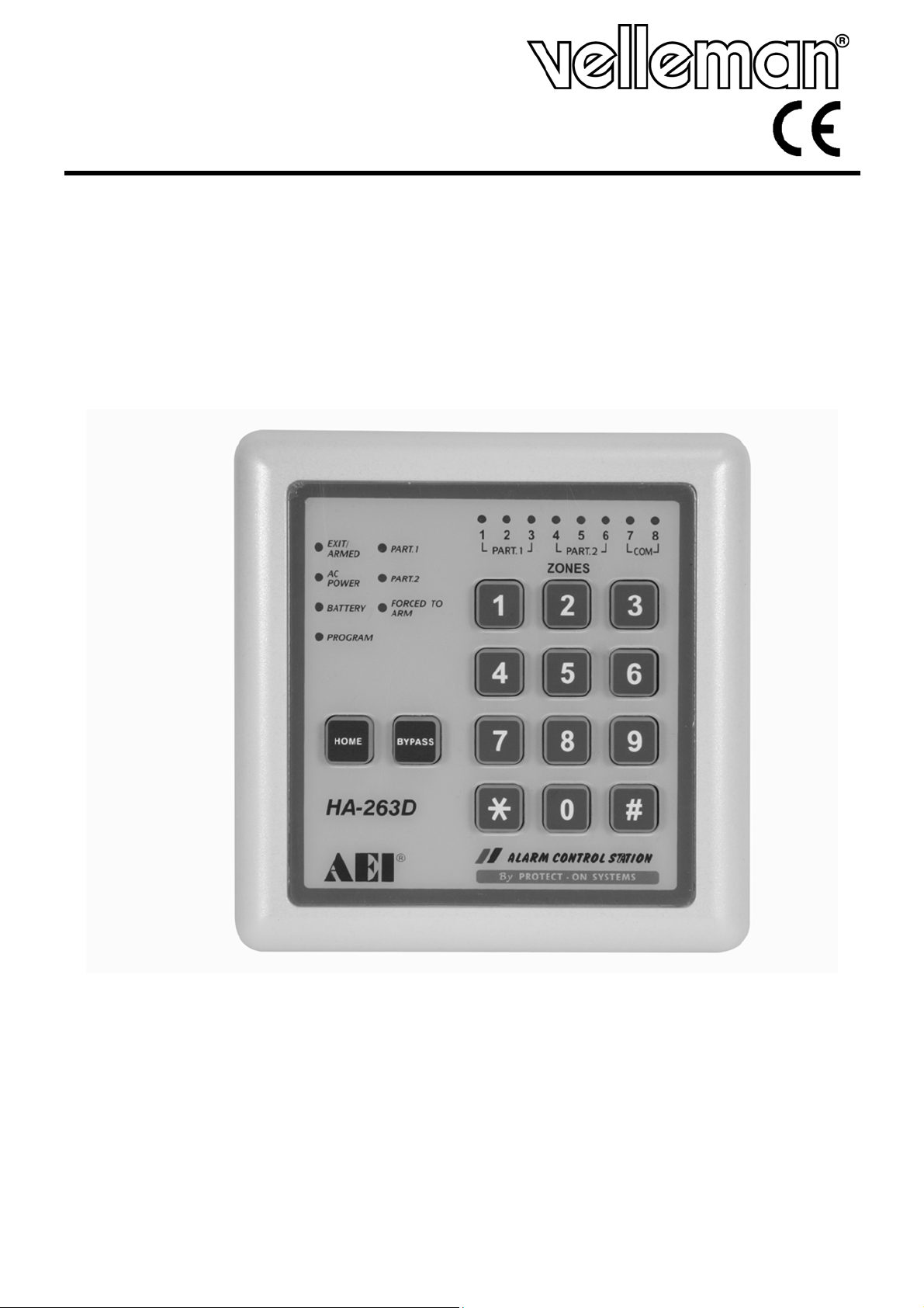
HAA263D
WEATHERPROOF CONTROL KEYPAD
WEERBESTENDIG BEDIENINGSPANEEL
PANNEAU DE COMMANDE RÉSISTANT AUX INTEMPÉRIES
PANEL DE CONTROL RESISTENTE A LA INTEMPERIE
WETTERFESTES BEDIENGERÄT
USER MANUAL 2
GEBRUIKERSHANDLEIDING 9
NOTICE D’EMPLOI 16
MANUAL DEL USUARIO 23
BEDIENUNGSANLEITUNG 31
Page 2

HAA263D
2
USER MANUAL
1. Introduction
To all residents of the European Union
Important environmental information about this product
This symbol on the device or the package indicates that disposal of the device after its
lifecycle could harm the environment. Do not dispose of the unit (or batteries) as
unsorted municipal waste; it should be taken to a specialized company for recycling. This
device should be returned to your distributor or to a local recycling service. Respect the
local environmental rules.
If in doubt, contact your local waste disposal authorities.
Thank you for choosing Velleman! Please read the manual thoroughly before bringing this device into
service. If the device was damaged in transit, do not install or use it and contact your dealer.
The HAA263D is a control keypad for the HAM263D alarm system. The alarm system can be
controlled by one single (master) keypad, or in a configuration with multiple (up to 4) HAA263D
control keypads, giving the user the flexibility to control the alarm system from different locations.
Simply connect the auxiliary keypad(s) in parallel with the leads of the master keypad; they will
have the exact same functionality as the master keypad.
2. Safety Instructions
Keep the device away from children and unauthorised
users.
• Damage caused by disregard of certain guidelines in this manual is not covered by the warranty and
the dealer will not accept responsibility for any ensuing defects or problems.
• Keep the device away from splashing and dripping liquids.
• Note that damage caused by user modifications to the device is not covered by the warranty.
3. General Guidelines
• Protect this device from shocks and abuse. Avoid brute force when operating the device.
• Protected the device against extreme heat, dust and moisture.
• Familiarise yourself with the functions of the device before actually using it.
• All modifications of the device are forbidden for safety reasons.
• Only use the device for its intended purpose. Using the device in an unauthorised way will void the
warranty.
4. Features
• weatherproof control keypad
• set up master code for programming authorization
• software panic function (by pressing any two buttons simultaneously for +3 seconds)
• bypass the un-used and/or faulty zone(s)
• put the frequently bypassed zone(s) in memory for HOME mode.
• show the faulty zone(s) during disarmed condition with user code
• arm system instantly without delay
• clear the alarm memory of the whole system or only specific sections
• initiate dynamic battery test at anytime during disarmed mode
• initiate a 5-second operation of both timing and latch output relays to test the connected
siren/strobe light
• system code for direct access to programming mode in case the master code is forgotten
• fully Compatible with HAM263D alarm systems
• up to 4 keypads can be connected to the alarm system (HAM263D)
• extra keypads have the exact same functionality as the master keypad
• simply connect extra keypads in parallel with the master keypad
• long connection distance possible, up to 500 metres
02 (15/11/2013) VELLEMAN
Page 3
HAA263D
3
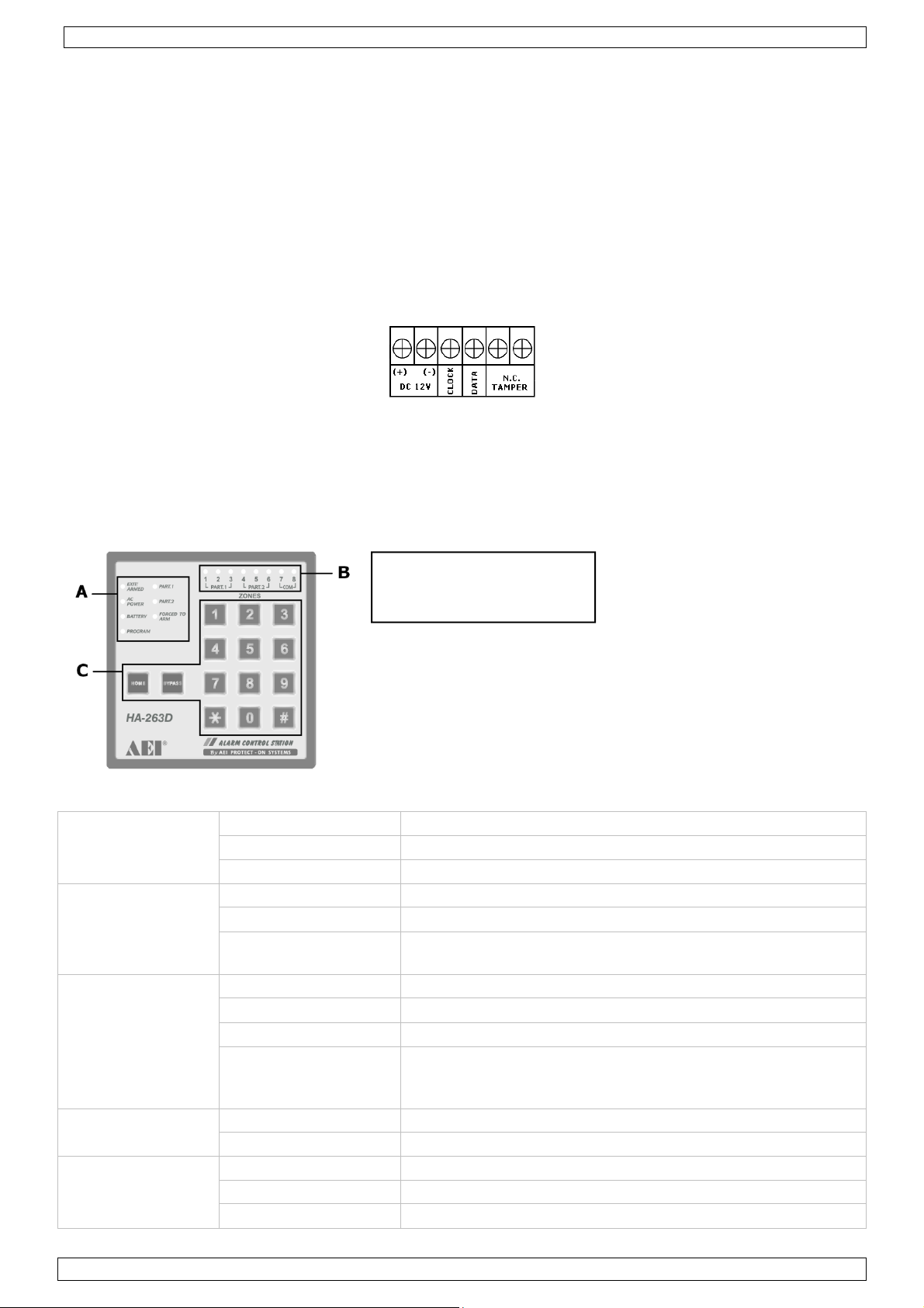
5. Installation
• This keypad should be installed and serviced by a qualified person only.
• Choose an easily accessible location where the keypad is protected from harsh environmental
conditions such as rain and bright sunlight, and away from heat producing devices.
• Have a qualified person installing the electrical leads (4) that are necessary for the connection of
the keypad to the master control unit.
• Remove the keypad from the mounting frame by removing the screw at the bottom and pulling
gently forward.
• Mount the mounting frame over the leads coming from the master control unit. Do not damage
the leads when doing this.
• Remove the back cover of the keypad by removing the screws at the four corners.
• Make sure there is no power on the leads. Connect the leads to the connector block in the keypad
as indicated on the PCB.
• It is also possible to install a tamper switch (not included).
• Re-mount the back cover with the 4 screws.
• Place the keypad back in the mounting frame. Make sure the cabling is not damaged in the
process. Remount the screw at the bottom.
• Apply power to the leads (via the master control unit).
• There are no user-serviceable parts. Contact your dealer for spare parts if necessary.
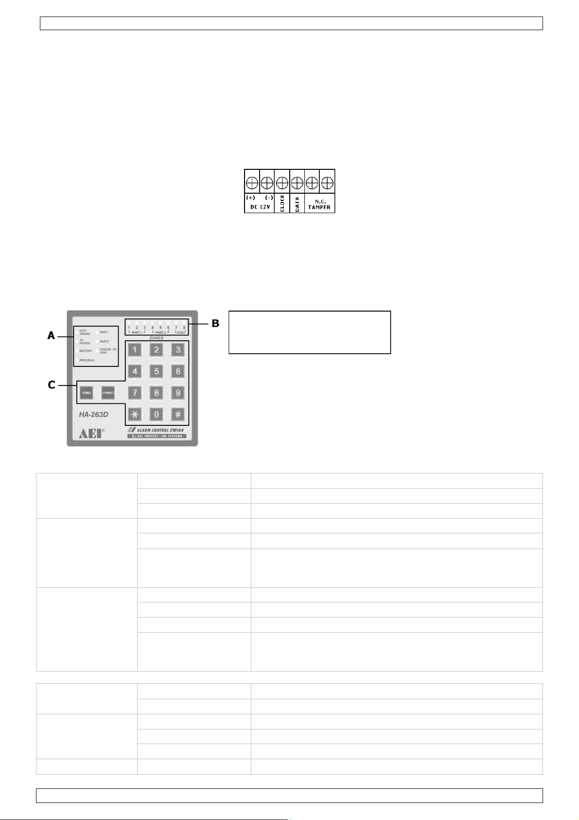
6. Keypad description
A. General status LEDs
B. Zone status LEDs
C. Control key buttons
A. General status LEDs
EXIT/ARMED ON System armed (whole system or one of the partitions)
OFF System disarmed (the whole system)
Flash System in exit delay period
AC POWER ON AC power normal
Flash AC power failure
Flash Alternatively
with Battery LED
BATTERY ON Battery low
OFF Battery normal
Flash Battery under testing
Flash Alternatively
with AC power
LED
PROGRAM ON System in programming mode
OFF System in normal operation mode
PART. 1 ON Partition 1 armed
OFF Partition 1 disarmed
Flash During Exit Delay
System in Standby mode
System in Standby mode
02 (15/11/2013) VELLEMAN
Page 4
HAA263D
4
•
•
PART. 2 ON Partition 2 armed
OFF Partition 2 disarmed
Flash During Exit Delay
FORCED TO ARM ON System will be forced to arm if the faulty zone is not
cleared
OFF System armed normally
Flash System forced to arm with the faulty zone(s) bypassed
by the system
B. Zone status LEDs
ON Zone abnormal
OFF Zone normal
Fast flashing Zone was or still is in alarm mode
Fast flashing, 3x with
stopping interval
Zone was in alarm mode and is stored in alarm memory. System
is disarmed
Slow flashing Zone is bypassed
C. Control key buttons description
There are 14 buttons for code entry and function confirmation
0 ~ 9 Numeric buttons for code entry
* # For function confirmation
HOME For home mode arming and programming
BYPASS For (temporarily) bypassing zones while arming system
D. Audible keypad notifications
1 short beep Successful key entry
2 short beeps Successful code entry for a specific function
5 short beeps
1 long beep Exit delay expired, system is armed
1 short beep/30 seconds Battery low or AC power failure
Continuous short beeps at 0.5
second interval
• Beeping increases to 4 beeps/second
at the last 10 seconds
• 1 long beep at the end of the period
4 short beeps with 1 second interval After an alarm condition before the system is
Unsuccessful code entry
• Code entry time expired (Maximum Allowable
Time:10 seconds/digit, 60 seconds/code)
During the Exit delay, Entry delay and System
Standby period
disarmed
7. Programming
a. Set programming mode
• Make sure the system is in disarmed mode and the alarm memory is empty.
• Enable programming mode with the master code. Key in the master code, followed by . The
system generates 2 beeps for successful and 5 beeps for unsuccessful code entry.
• Factory default master code is 1234. For security reasons, it is strongly advised to replace this
master code with a personal code.
•
The PROGRAM LED is on and the system stops all its detection activities.
02 (15/11/2013) VELLEMAN
Page 5
HAA263D
5
b. Reset master code
If you have forgotten the master code, you can reset it. For the master code, do not use a
combination that is already taken for a user code.
In case the master code is forgotten, use the following procedure to enable programming mode:
1. Switch off both AC and battery power for at least one minute.
2. Switch power back on. This will bring the system in standby mode for one minute. The AC
power and the battery LED flash alternately, and short beeps are heard.
3. During standby mode, key in code 8080, followed by .
Note: this procedure will only work during standby mode after power-up.
c. Start programming
After the system is set to programming mode, the available options can be set. It is not necessary
to follow a certain sequence; jumping to any available programming location is possible.
Every programming code consists of three parts: the location, the value and the validation. These
are entered sequentially without any characters in between:
XXyyyyyy#
XX = Location in memory
yyyyyy = value
d. Record a master code
# = validation
Notes: master code
-
When programming the codes, it is recommended to program the master code
before the user codes.
-
If you are programming a new master code, do not use a combination that is already
taken for a user code.
-
-
The master code is the authorization code for setting the system in programming mode.
-
It can consist of 4 to 6 digits.
-
After entering a new master code, the old one is erased.
-
Format:
If you have forgotten the master code, you can reset it. See b. Reset master code.
01yyyyyy#
01 master code
yyyyyy = 4 to 6 digits
# = validation
e. Record a user code
Notes: user code
-
Any user code must be different from the master code.
-
It is recommended to program a different code for every user.
• It can consist of 4 to 6 digits.
• After entering a new user code, the old one is replaced.
• To remove a user code, key in the location, immediately followed by #.
• Format:
XXyyyyyy#
XX = 11 USER CODE 1 for arm/disarm control of part. 1
12 USER CODE 2 for arm/disarm control of part. 2
13 USER CODE 3 for arm/disarm control of the
whole system (partition 1 and 2)
yyyyyy = 4 to 6 digits
b. Memorize frequently bypassed zones (“HOME” mode)
# = validation
02 (15/11/2013) VELLEMAN
Page 6
HAA263D
6
• HOME mode is only available for use with USER CODE 3 (whole system). However, partitions
can be bypassed by bypassing the zones within the partition one by one.
• Zone 8 (24 hour zone) is excluded from use in HOME mode
• Format:
HOMEyyyyyy#
HOME Press HOME button on keypad
yyyyyy = List of zones to be enabled, sequential e.g. 245 to
bypass zones 2, 4 and 5
# = validation
• To use the home mode, simply type USER CODE 3, and ; all programmed zones will
automatically be bypassed.
c. Keypad audible notification set-up
• Some audible notification can be passed on to the keypad. This is the case for the exit and entry
delay, after an alarm condition and for each key button press.
• Alarm conditions concerning battery low or AC power failure conditions are always ON.
• Passing these notifications through to the keypad will not affect the beep settings on the master
control unit.
• Note that confirmation beeps from the -button and -button are always enabled.
14yyyy#
14 master code
yyyy = 4 digits: 0=beep disabled, 1=beep enabled (default)
digit 1 Beep for exit delay
digit 2 Beep for entry delay
digit 3 Beep after alarm condition
digit 4 Beep after each key button press
# = validation
d. Alarm detection response time
• The default zone response time is set to 500ms. This setting can be adjusted independently per
zone, depending on the conditions in that zone.
• The 8 digit code represents the 8 protection zones. The first digit is zone 1 and the last digit is
zone 8. By putting the timing codes into the specific digit to independently the desired response
time can be set.
15yyyyyyyy#
14 master code
yyyyyyyy = 8 digits, default setting = 3
1 25 ms
2 250 ms
3 500 ms
4 750 ms
e. Reset system to default
# = validation
• To reset the system to its default values, enter code 2100#.
Except for the master code, all other values will be cleared or set to their default.
•
f. Exit programming mode
To leave programming mode, type .
•
8. Operation
This system is designed with "FORCED TO ARM" operation. If faulty zones exist it will bypass the
faulty zones automatically after it is armed. The LED of the faulty zones will flash to indicate that
they are not protected and the "FORCED TO ARM" LED will also flash to indicate that the system is in
“Forced To Arm”-mode with the faulty zones bypassed.
a. Arm the system with exit delay
02 (15/11/2013) VELLEMAN
Page 7
HAA263D
7
• Make sure that the alarm system is in disarmed mode and the alarm memory is empty. If the
memory is not empty, clear it first (see below).
•
Enter an appropriate USER CODE and validate with key.
2-beeps confirm correct code entry, exit delay starts and EXIT/ARMED LED flashes.
•
• 5-beeps indicate incorrect code entry. Enter the code again.
• System will arm after exit delay expires. The appropriate partition LED and the EXIT/ARMED LED
are ON.
b. Arm the system instantly
• Make sure that the alarm system is in disarmed mode and the alarm memory is empty. If the
memory is not empty, clear it first (see below).
•
Enter an appropriate USER CODE, , and .
2-beeps confirm correct code entry and the system arms instantly without exit delay. The
•
appropriate partition LED and the EXIT/ARMED LED are ON.
5-beeps indicate incorrect code entry. Enter the code again.
•
Note: as there is no exit delay, walking through the protected area will trigger the alarm. Mount
c. Arm the system in home mode with exit delay
the keypad outside the protected zone to use this function.
• This function only works with USER CODE 3. The protection zones that are stored in memory will
be bypassed when arming. The bypassed zones are not monitored and will not trigger alarms.
•
Enter USER CODE 3, and .
• 2-beeps confirm correct code entry, exit delay starts and EXIT/ARMED LED flashes.
5-beeps indicate incorrect code entry. Enter the code again.
•
• The LEDs indicating the bypassed zones will flash constantly.
• System will arm after exit delay expires. The appropriate partition LED and the EXIT/ARMED LED
are ON.
Note: in HOME mode, USER CODE 1 and 2 can still be used to disarm the partitions.
d. Arm the system in home mode instantly
• This function only works with USER CODE 3. The protection zones that are stored in memory
will be bypassed when arming. The bypassed zones are not monitored and will not trigger
alarms.
•
Enter USER CODE 3, , and .
2-beeps confirm correct code entry and the system arms instantly without exit delay.
•
e. Arm the system with manual bypass
• This function allows the temporary bypassing of protection zones, e.g. faulty zones.
• USER CODE 1 can only bypass zones in partition 1 while USER CODE 2 can only bypass zones
in partition 2. With USER CODE 3, all zones can be bypassed.
Make sure that the alarm system is in disarmed mode and the alarm memory is empty. If the
•
memory is not empty, clear it first (see below).
•
Enter the appropriate USER CODE, , the zone numbers that need to be bypassed and
.
•
2-beeps confirm correct code entry, exit delay starts and EXIT/ARMED LED flashes.
• 5-beeps indicate incorrect code entry. Enter the code again.
• The LEDs indicating the bypassed zones will flash constantly.
System will arm after exit delay expires. The appropriate partition LEDs and the EXIT/ARMED
•
LED are ON.
• The manual setting of bypassed zones is lost when the system is disarmed.
f. Disarm the system
Simply enter an appropriate USER CODE and within the entry delay period.
•
• The system disarms instantly.
• 2-beeps confirm correct code entry.
• 5-beeps indicate incorrect code entry. Enter the code again after the beeps.
g. Clear the alarm memory
Before the system can be re-armed in a normal way, the alarm memory must be cleared.
02 (15/11/2013) VELLEMAN
Page 8
HAA263D
8
• Enter an appropriate USER CODE, , and .
• All zone LEDs will turn off.
• The system is in disarmed mode and can be re-armed at any time.
h. Panic button function
At anytime, pressing and holding down any TWO buttons on the keypad simultaneously for more
than three seconds will trigger an alarm. This 24 hour emergency alarm is a software alarm which
is indicated as zone 8. It can not be changed.
i. Check faulty zone(s)
• Make sure the system or partition is in disarmed condition.
• Enter the appropriate USER CODE,
, and .
• The LEDs of the faulty zone(s) will light up.
• Each display period is 30 seconds. At the end of the period, a beep is generated. If any button is
pressed within 5 seconds after that beep, a new period of 30 seconds begins. The display period
may be prolonged as many times as necessary.
• The system resumes to normal operation 5 seconds after the beep if no button press is detected.
• The system does not allow to arm during faulty zone checking and the keypad is temporarily
disabled.
j. Dynamic battery test
• The system automatically tests the backup battery once every 24 hours.
• To initiate a dynamic battery test, disarm the alarm system.
• Enter USER CODE,
, and . The battery LED will flash.
• Manually initiated testing does not affect the periodic battery test.
• The test takes 5 seconds to 2 minutes depending on the condition of the battery.
• Manually battery test is usually required after installation of a new back-up battery.
k. Dynamic output relay test
Visible and audible alarm indicators e.g. siren, strobe light ..., are connected to the output relays.
It is important to periodically ensure that these relays still function properly.
• To initiate a dynamic output relays test, disarm the alarm system.
• Enter USER CODE,
• Both timing and latch output relays operate for 5 seconds. Verify that all
, and .
visible and audible
alarm indications e.g. sirens, strobe light… are functional.
• If an alarm indicator is not working, check the wiring and the device immediately.
• It is advisable to run this test on a monthly basis.
9. Technical specifications
Operating Voltage 12VDC (provided by HAM263D)
Dimensions 117 x 117 x 27mm
Weight 220g
Use this device with original accessories only. Velleman nv cannot be held responsible in
the event of damage or injury resulted from (incorrect) use of this device.
For more info concerning this product, please visit our website www.velleman.eu.
The information in this manual is subject to change without prior notice.
02 (15/11/2013) VELLEMAN
Page 9
HAA263D
9
GEBRUIKERSHANDLEIDING
1. Inleiding
Aan alle ingezetenen van de Europese Unie
Belangrijke milieu-informatie betreffende dit product
Dit symbool op het toestel of de verpakking geeft aan dat, als het na zijn levenscyclus
wordt weggeworpen, dit toestel schade kan toebrengen aan het milieu. Gooi dit toestel (en
eventuele batterijen) niet bij het gewone huishoudelijke afval; het moet bij een
gespecialiseerd bedrijf terechtkomen voor recyclage. U moet dit toestel naar uw verdeler of
naar een lokaal recyclagepunt brengen. Respecteer de plaatselijke milieuwetgeving.
Hebt u vragen, contacteer dan de plaatselijke autoriteiten inzake verwijdering.
Dank u voor uw aankoop! Lees deze handleiding grondig voor u het toestel in gebruik neemt. Werd
het toestel beschadigd tijdens het transport, installeer het dan niet en raadpleeg uw dealer.
De HAA263D is een bedieningspaneel voor het HAM263D alarmsysteem. Het alarmsysteem kan
worden bediend via een enkel paneel (hoofdpaneel) of in een configuratie met meerdere HAA263Dpanelen (max. vier) voor de maximale flexibiliteit. Sluit eenvoudigweg het paneel in parallel aan het
hoofdpaneel. Het supplementaire paneel heeft dezelfde functionaliteit als het hoofdpaneel.
2. Veiligheidsinstructies
Houd dit toestel weg van kinderen en onbevoegde
personen.
• De garantie geldt niet voor schade door het negeren van bepaalde richtlijnen in deze handleiding
en uw dealer zal de verantwoordelijkheid afwijzen voor defecten of problemen die hier
rechtstreeks verband mee houden.
• Houd dit toestel uit de buurt van opspattende en druppelende vloeistoffen.
• Schade door wijzigingen die de gebruiker heeft aangebracht aan het toestel vallen niet onder de
garantie.
3. Algemene richtlijnen
• Bescherm dit toestel tegen schokken. Vermijd brute kracht tijdens de bediening van dit toestel.
• Bescherm dit toestel tegen extreme temperaturen, stof en vochtigheid.
• Leer eerst de functies van het toestel kennen voor u het gaat gebruiken.
• Om veiligheidsredenen mag de gebruiker geen wijzigingen aanbrengen aan het toestel.
• Gebruik het toestel enkel waarvoor het gemaakt is. Bij onoordeelkundig gebruik vervalt de
garantie.
4. Eigenschappen
• weerbestendig bedieningspaneel
• toegang tot de programmering via master code
• paniektoets via software (door gedurende 3 seconden gelijktijdig op twee toetsen te drukken)
• bypass van de ongebruikte en/of foutieve zone(s)
• opslag van de bypasszone(s) voor HOME-gebruik
• weergave van de foutieve zone(s) tijdens stand-by via invoer van de gebruikerscode
• directe scherpstelling van het systeem zonder vertraging
• totaal of gedeeltelijk wissen van het alarmgeheugen
• batterijtest tijdens stand-by
• synchronisatietest tussen het deurslot en sirene/zwaailicht
• systeemcode voor directe toegang tot de programmeermodus bij verlies van de master code
• volledig compatibel met de HAM263D
• aansluiting mogelijk tot vier bedieningspanelen
• extra panelen hebben dezelfde functionaliteit als het hoofdpaneel
• eenvoudige aansluiting in parallel met het hoofdpaneel
• lange aansluiting tot 500 meter mogelijk
5. Installatie
• Laat dit bedieningspaneel enkel installeren en onderhouden door een geschoold technicus.
02 (15/11/2013) VELLEMAN
Page 10

HAA263D
10
• Kies een geschikte montageplaats uit de zon en beschermd tegen regen en hitte.
• Laat de elektrische aansluiting tussen het bedieningspaneel en het hoofdpaneel uitvoeren door een
geschoold technicus.
• Bevrijd het bedieningspaneel door de schroef onderaan los te schroeven en het paneel zachtjes uit
het frame te duwen.
• Monteer het frame over de bekabeling afkomstig van het hoofdpaneel. Zorg ervoor dat u de
kabel niet beschadigt.
• Verwijder de schroef in elke hoek en open het bedieningspaneel.
• Zorg ervoor dat het paneel niet onder stroom staat. Sluit de kabels aan het aansluitblok van het
paneel zoals op de printplaat weergegeven.
• Koppel een antisabotageschakelaar (niet meegeleverd) indien gewenst.
• Sluit het bedieningspaneel met de vier schroeven.
• Plaats het paneel terug in zijn frame zonder de bekabeling te beschadigen. Bevestig het frame aan
het paneel met de schroef.
• Zet het bedieningspaneel onder stroom (via het hoofdpaneel).
• De gebruiker mag geen onderdelen vervangen. Bestel eventuele reserveonderdelen bij uw dealer.
6. Omschrijving bedieningspaneel
A. algemene statusleds
B. infoleds alarmzones
C. toetsenbord
A. Algemene statusleds
EXIT/ARMED Aan Systeem ingeschakeld (hele systeem of een van de
partities)
Uit Systeem uitgeschakeld (hele systeem)
Flitsen Systeem in ingangsvertraging
AC POWER Aan Voeding normaal
Flitsen Voeding onderbroken
Beurtelings flitsen
met batterijled
BATTERY Aan Zwakke batterij
Uit Batterij normaal
Flitsen Batterij in testfase
Beurtelings flitsen
met voedingsled
PROGRAM Aan Systeem in programmeerfase
Uit Systeem in normale gebruikersfase
PART. 1 Aan Partitie 1 ingeschakeld
Uit Partitie 1 uitgeschakeld
Flitsen Inschakelvertraging
PART. 2 Aan Partitie 2 ingeschakeld
Uit Partitie 2 uitgeschakeld
Flitsen Ingangsvertraging
Systeem in stand-by
Systeem in stand-by
02 (15/11/2013) VELLEMAN
Page 11
HAA263D
11
•
•
FORCED TO ARM Aan Het systeem wordt ingeschakeld indien de defecte zone
niet vrijgegeven is
Uit Systeem normaal ingeschakeld
Flitsen Het systeem wordt ingeschakeld en de defecte zone
wordt gebypasst
B. Infoleds alarmzones
Aan Zone is normaal
Uit Zone is normaal
Snelle flitsen Zone was of is bewaakt
Snelle flitsen, 3x met
interval
Zone was bewaakt en wordt in het geheugen opgeslagen.
Systeem is uitgeschakeld.
Trage flitsen Zone is overgeslagen
C. Omschrijving van de bedieningstoetsen
De code wordt ingegeven en bevestigd door middel van 14 toetsen.
0 ~ 9 Cijfertoetsen voor het ingeven van de code
* # Bevestigen van de functie
HOME Programmering en inschakeling
BYPASS Tijdelijk overslagen van bepaalde zones bij inschakeling van het systeem
D. Pieptonen
1 korte pieptoon Ingedrukte toets is aanvaard
2 korte pieptonen Ingedrukte code is aanvaard
5 korte pieptonen
1 lange pieptoon Ingangsvertraging verstreken, systeem is
1 korte pieptoon/30 seconden Zwakke batterij of voedingsprobleem
Onophoudelijk korte pieptonen met
interval van 0,5 seconde
• Tot 4 pieptonen/seconde
• 1 lange pieptoon op het einde
4 korte pieptonen met interval van 1
seconde
Code fout ingetoetst
• Max. toegestane tijd voor het ingeven van de
code is verstreken (max. toegestane tijd van 10
seconden/digit, 60 seconden/code)
ingeschakeld
Ingang-/uitgangsvertraging en systeem in standby
Na alarm alvorens het systeem wordt
uitgeschakeld
7. Programmering
a. De programmeermodus inschakelen
• Zorg dat het alarmsysteem is uitgeschakeld en dat het geheugen leeg is.
• Geef de master code in, gevolgd door . Het systeem piept tweemaal indien de code werd
aanvaard of vijfmaal indien de code niet werd aanvaard.
• De standaardcode is 1234. Voor veiligheidsredenen is het aangeraden deze standaardcode door
een persoonlijke geheime code te vervangen.
De PROGRAM-led licht op en het alarmsysteem wordt tijdelijk uitgeschakeld.
•
b. Mastercode resetten
Bent u de mastercode vergeten, dan kunt u deze resetten. Gebruik voor het programmeren van de
mastercode, geen combinatie die reeds toegekend is aan een gebruikerscode.
02 (15/11/2013) VELLEMAN
Page 12
HAA263D
12
1. Onderbreek zowel de net- als batterijvoeding gedurende minstens een minuut.
2. Zet het systeem opnieuw onder stroom. Het systeem staat nu gedurende een minuut in
stand-by.
De voedingsled en de batterijled flitsen beurtelings en het systeem piept kort.
In stand-by, geef code 8080 in, gevolgd door ..
3.
Opmerking: Deze procedure is enkel geldig in stand-by na inschakeling.
c. Programmering
In de programmeermodus kunt u de beschikbare opties ingeven. U hoeft de opties niet in een
bepaalde volgorde ingeven – het is mogelijk om van de ene locatie naar de andere over te
springen. Elke code bestaat uit drie delen: de locatie, de waarde en de bevestiging. Geef de code
in zonder spaties:
XXyyyyyy#
XX = locatie in het geheugen
yyyyyy = waarde
# = bevestiging
d. Een master code programmeren
Opmerkingen: mastercode
-
Programmeer eerst de mastercode en daarna de gebruikerscodes.
-
Gebruik voor het programmeren van een nieuwe mastercode, geen combinatie die
reeds toegekend is aan een gebruikerscode.
-
Bent u de mastercode vergeten, dan kunt u deze resetten. Zie b. Mastercode
-
Met de master code kunt u de programmeermodus van het alarmsysteem weergeven.
-
Deze master code bestaat uit 4 to 6 digits.
-
Bij het bevestigen van de nieuwe master code wordt de oude gewist.
-
Formaat:
resetten.
01yyyyyy#
01 master code
yyyyyy = 4 tot 6 digits
# = bevestiging
e. Een gebruikerscode programmeren
Opmerkingen: gebruikerscode
-
De gebruikercodes moeten verschillend zijn van de mastercode.
-
Programmeer een andere code voor elke gebruiker.
• Een gebruikerscode bestaat uit 4 tot 6 digits.
• Bij het bevestigen van de nieuwe gebruikerscode wordt de oude gewist.
• Wis een gebruikerscode door de locatie in te geven, gevolgd door #.
• Formaat:
XXyyyyyy#
XX = 11 GEBRUIKERSCODE 1 voor in-/uitschakeling van partitie 1
12 GEBRUIKERSCODE 2 voor in-/uitschakeling van partitie 2
13 GEBRUIKERSCODE 3 voor in-/uitschakeling van het hele
systeem (partitie 1 en 2)
yyyyyy = 4 tot 6 digits
# = bevestiging
f. Een niet-bewaakte zone bepalen (HOME-optie)
• De HOME-optie is enkel beschikbaar voor gebruik met GEBRUIKERSCODE 3 (hele systeem).
Partities kunnen echter gebypasst worden door elke zone binnenin die partitie uit te schakelen.
• Zone 8 (24-uurzone) is niet beschikbaar.
02 (15/11/2013) VELLEMAN
Page 13
HAA263D
13
• Formaat:
HOMEyyyyyy#
HOME druk op HOME op het bedieningspaneel
yyyyyy = lijst van in te schakelen zones, sequentieel bv. 245 tot
bypasszone 2, 4 en 5
# = bevestiging
• Om de HOME-optie te gebruiken, typ GEBRUIKERSCODE 3, en . Alle
geprogrammeerde zones worden automatisch overgeslagen.
g. De pieptonen op het bedieningspaneel instellen
• Een aantal pieptonen zijn over te dragen aan het bedieningspaneel, nl. de ingang- en
uitgangsvertraging na een alarm en elke toetsdruk.
• Pieptonen voor de zwakke batterij of de stroomonderbreking zijn altijd ingeschakeld (ON).
• Het overdragen van deze pieptonen aan het bedieningspaneel zal de instellingen op het
hoofdpaneel niet beïnvloeden.
• Merk op dat de geluidsmeldingen voor de toets en ingeschakeld blijven.
14yyyy#
14 Master code
yyyy = 4 digits: 0=geen pieptoon, 1=pieptoon (standaard)
digit 1 Pieptoon voor uitgangsvertraging
digit 2 Pieptoon voor ingangsvertraging
digit 3 Pieptoon na alarm
digit 4 Pieptoon bij indrukken toets
h. De responstijd instellen
# = Bevestiging
• De standaard responstijd staat ingesteld op 500 ms. Deze tijd kan voor elke zone afzonderlijk
worden ingesteld, naargelang de omstandigheden in die zone.
•
De 8-cijferige code staat voor de 8 veiligheidszones. Het eerste cijfer geeft zone 1 weer en het
laatste is zone 8. Via deze code kunt u de responstijd voor elke zone naar wens instellen.
15yyyyyyyy#
14 master code
yyyyyyyy = 8 digits, standaardinstelling = 3
1 25 ms
2 250 ms
3 500 ms
4 750 ms
i.Fabrieksinstellingen
# = bevestiging
• Geef code 2100# in om de fabrieksinstellingen opnieuw in te stellen.
• Alle waarden worden gewist, uitgenomen de master code.
j. De programmeermodus verlaten
•
Geef in om de programmeermodus te verlaten.
8. Gebruik
Dit systeem gebruikt FORCED TO ARM. De defecte zones worden na de inschakeling automatisch
gebypasst. De led van de defecte zones knippert om aan te geven dat ze niet beveiligd zijn. De
FORCED TO ARM-led knippert ook om aan te geven dat het systeem is ingeschakeld en dat de
defecte zones zijn gebypasst.
a. Het alarmsysteem inschakelen met inschakelvertraging
• Schakel het alarmsysteem uit en wis het geheugen (zie hieronder).
Geef de correcte GEBRUIKERSCODE in en bevestig met .
•
02 (15/11/2013) VELLEMAN
Page 14

HAA263D
14
• Twee pieptonen geven aan dat de code correct is ingegeven. De inschakelvertraging start en de
led van EXIT/ARMED knippert.
• Vijf pieptonen geven aan dat de code niet correct is ingegeven. Geef de code correct in.
Het alarmsysteem schakelt in nadat de vertraging is verstreken. De led van de toepasselijke
•
partitie en van EXIT/ARMED licht op.
b.Het alarmsysteem onmiddellijk inschakelen
• Schakel het alarmsysteem uit en wis het geheugen (zie hieronder).
Geef de correcte GEBRUIKERSCODE in en druk op , en .
•
Twee pieptonen geven aan dat de code correct is ingegeven. Het alarmsysteem wordt
•
onmiddellijk en zonder vertraging ingeschakeld. De led van de toepasselijke partitie en van
EXIT/ARMED licht op.
• Vijf pieptonen geven aan dat de code niet correct is ingegeven. Geef de code correct in.
Opmerking: Het alarm gaat af indien u in de bewaakte zone loopt aangezien er geen vertraging
is. Wenst u het systeem zonder vertraging in te schakelen, dan monteert u het
c. Het alarmsysteem inschakelen met inschakelvertraging in HOME-optie
bedieningspaneel best buiten de bewaakte zone.
• Deze optie is enkel beschikbaar met GEBRUIKERSCODE 3. De zones die in het geheugen zijn
opgeslagen, worden bij inschakeling gebypasst. De gebypasste zones worden niet bewaakt en
kunnen het alarm niet doen afgaan.
•
Geef GEBRUIKERSCODE 3 in en druk op en .
Twee pieptonen geven aan dat de code correct is ingegeven. De inschakelvertraging start en de
•
led van EXIT/ARMED knippert.
• Vijf pieptonen geven aan dat de code niet correct is ingegeven. Geef de code correct in.
• De leds die de gebypasste zones weergeven knipperen onophoudelijk.
•
Het alarmsysteem schakelt in nadat de vertraging is verstreken. De led van de toepasselijke
partitie en van EXIT/ARMED licht op.
Opmerking: In de HOME-optie kunt u de GEBRUIKERSCODE 1 en 2 gebruiken om de partities
uit te schakelen.
d.Het alarmsysteem onmiddellijk inschakelen in HOME-optie
• Deze optie is enkel beschikbaar met GEBRUIKERSCODE 3. De zones die in het geheugen zijn
opgeslagen, worden bij inschakeling gebypasst. De gebypasste zones worden niet bewaakt en
kunnen het alarm niet doen afgaan.
Geef GEBRUIKERSCODE 3 in en druk op , en .
•
• Twee pieptonen geven aan dat de code correct is ingegeven. Het alarmsysteem wordt
onmiddellijk en zonder vertraging ingeschakeld.
e. Het alarmsysteem inschakelen en handmatig bypassen
• Deze optie laat toe defecte zones tijdelijk uit te schakelen.
• Met GEBRUIKERSCODE 1 kunt u enkel de zones in partitie 1 bypassen, met
GEBRUIKERSCODE 2 kunt u enkel de zones in partitie 2 bypassen. Met GEBRUIKERSCODE 3
kunt u alle zones bypassen.
• Schakel het alarmsysteem uit en wis het geheugen (zie hieronder).
•
Geef de correcte GEBRUIKERSCODE in en druk op , het zonenummer dat u wenst te
bypassen en .
Twee pieptonen geven aan dat de code correct is ingegeven. De inschakelvertraging start en de
•
led van EXIT/ARMED knippert.
• Vijf pieptonen geven aan dat de code niet correct is ingegeven. Geef de code correct in.
•
De leds van de gebypasste zones knipperen onophoudelijk.
• Het alarmsysteem schakelt in nadat de vertraging is verstreken. De led van de toepasselijke
partitie en van EXIT/ARMED licht op.
• De handmatig gebypasste zones worden na uitschakeling van het systeem uit het geheugen
gewist.
f. Het alarmsysteem uitschakelen
Geef eenvoudigweg de correcte GEBRUIKERSCODE in en druk op voor de
•
ingangsvertraging verstrijkt.
02 (15/11/2013) VELLEMAN
Page 15

HAA263D
15
• Het alarmsysteem wordt inmiddellijk uitgeschakeld.
• Twee pieptonen geven aan dat de code correct is ingegeven.
• Vijf pieptonen geven aan dat de code niet correct is ingegeven. Geef de code correct in na de
pieptonen.
g.Het geheugen wissen
Voor u het alarmsysteem kunt inschakelen, moet u het geheugen wissen.
• Geef de correcte GEBRUIKERSCODE in en druk op , en .
• Alle leds van de zones doven.
• Het alarmsystem staat niet meer op scherp en op elk moment opneiuw ingeschakeld worden.
h.De paniekfunctie
Houd TWEE toetsen gelijktijdig gedurende meer dan drie seconden ingedrukt om het alarm te
doen afgaan. Dit noodsignaal is een softwarealarm, aangeduid als zone 8, en kan niet gewijzigd
worden.
i.De defecte zones controleren
• Schakel het alarmsysteem of de partitie uit.
• Geef de correcte GEBRUIKERSCODE in en druk op
•
De leds van de defecte zones lichten op.
, en .
• Elke zone wordt gedurende 30 seconden gestest. Na elke test hoort u een pieptoon. Drukt u op
een toets binnen de 5 seconden na de pieptoon, dan start een nieuwe testperiode van 30
seconden. De testperiode kan naar wens hervat worden.
• Het systeem hervat de normale werking 5 seconden na de pieptoon (indien geen enkele toets
werd ingedrukt).
• Het alarmsysteem kan niet ingeschakeld worden tijdens deze test en het bedieningspaneel is
tijdelijk uitgeschakeld.
j. De batterij testen
• Het systeem test automatisch de noodbatterij eens om de 24 uur.
• Wenst u de batterij handmatig te testen, schakel dan eerst het alarmsysteem uit.
• Geef de correcte GEBRUIKERSCODE in en druk op
, en . De batterijled flitst.
• Een handmatige batterijtest beïnvloedt de periodieke batterijtest niet.
• De test duurt 5 seconden tot 2 minuten, afhankelijk van de batterij.
• Een handmatige batterijtest is aan te raden na het plaatsen van een verse noodbatterij.
k.De relaisuitgangen testen
Zichtbare en hoorbare alarmmeldingen zoals sirenes, flitslichten, enz. zijn aangesloten op
uitgangrelais. Een periodieke test van deze uitgangen garandeert een goede werking.
• Wenst u de uitgangen handmatig te testen, schakel dan eerst het alarmsysteem uit.
• Geef de correcte GEBRUIKERSCODE in en druk op
, en .
• De uitgangen voor de timing en het veerslot worden gedurende 5 seconden geactiveerd.
Controleer of alle z
ichtbare en hoorbare alarmmeldingen zoals sirenes, flitslichten, enz. correct
werken.
• Controleer de aansluiting van een defecte alarmmelding onmiddellijk.
• Een maandelijkse test van de uitgangen is aan te raden.
9. Technische specificaties
spanning 12 VDC (via de HAM263D)
afmetingen 117 x 117 x 27 mm
gewicht 220 g
Gebruik dit toestel enkel met originele accessoires. Velleman nv is niet aansprakelijk voor
schade of kwetsuren bij (verkeerd) gebruik van dit toestel. Voor meer informatie over dit
product, zie www.velleman.eu. De informatie in deze handleiding kan te allen tijde
worden gewijzigd zonder voorafgaande kennisgeving.
02 (15/11/2013) VELLEMAN
Page 16

HAA263D
16
NOTICE D’EMPLOI
1. Introduction
Aux résidents de l'Union européenne
Des informations environnementales importantes concernant ce produit
Ce symbole sur l'appareil ou l'emballage indique que l’élimination d’un appareil en fin de
vie peut polluer l'environnement. Ne pas jeter un appareil électrique ou électronique (et
des piles éventuelles) parmi les déchets municipaux non sujets au tri sélectif ; une
déchèterie traitera l’appareil en question. Renvoyer les équipements usagés à votre
fournisseur ou à un service de recyclage local. Il convient de respecter la réglementation
locale relative à la protection de l’environnement.
En cas de questions, contacter les autorités locales pour élimination.
Nous vous remercions de votre achat ! Lire la présente notice attentivement avant la mise en
service de l’appareil. Si l’appareil a été endommagé pendant le transport, ne pas l’installer et
consulter votre revendeur.
Le HAA263D est un panneau de commande supplémentaire pour le système d’alarme HAM263D. Le
système d’alarme est commandé à partir d’un panneau de commande central, ou dans une
configuration avec plusieurs (jusqu’à 4) panneaux de commande HAA263D permettant à
l’utilisateur une flexibilité d’utilisation maximale. Connectez tout simplement le(s) panneau(x)
supplémentaire(s) en parallèle au panneau central. Chaque panneau supplémentaire possède un
niveau de fonctionnalité identique à celui du panneau central.
2. Prescriptions de sécurité
Garder le panneau hors de la portée de personnes non
qualifiées et de jeunes enfants.
• La garantie ne s’applique pas aux dommages survenus en négligeant certaines directives de cette notice
et votre revendeur déclinera toute responsabilité pour les problèmes et les défauts qui en résultent.
• Tenir le panneau à l’écart d’éclaboussures et de jaillissements
• Les dommages occasionnés par des modifications à l’appareil par le client ne tombent pas sous la garantie.
3. Directives générales
• Protéger le panneau contre les chocs et le traiter avec circonspection pendant l’installation et l’opération.
• Tenir le panneau à l’écart de la poussière, l’humidité et des températures extrêmes.
• Se familiariser avec le fonctionnement de l’appareil avant de l’utiliser.
• Toute modification de l’appareil est interdite pour des raisons de sécurité.
• N’utiliser le thermomètre qu’à sa fonction prévue. Tout autre usage peut causer des courts-
circuits, des brûlures, des électrochocs, etc. Un usage impropre annule d'office la garantie.
4. Caractéristiques
• panneau de commande résistant aux intempéries
• accès au paramétrage grâce au code maître
• fonction panique via logiciel (pression simultanée de deux touches pendant > 3 secondes)
• omission des zones non utilisées et/ou anomaliques
• sauvegarde en mémoire des zones omises pour utilisation en mode HOME
• affichage des zones anomaliques en mode veille grâce au code maître
• armement du système d’alarme sans délai d’entrée
• effacement complet ou partiel de la mémoire
• test de la pile de secours en mode veille
• test de synchronisation entre la serrure et la sirène
• code maître direct au mode de paramétrage en cas de perte du code maître
• compatible avec le système d’alarme HAM263D
• possibilité de connexion jusqu’à 4 panneaux supplémentaires au système d’alarme HAM263D
• les panneaux supplémentaires possèdent un niveau de fonctionnalité identique à celui du panneau central
• raccordement en parallèle au panneau central
• possibilité de distance de raccordement jusqu’à 500 mètres
02 (15/11/2013) VELLEMAN
Page 17

HAA263D
17
5. Installation
• Confier l’installation à un technicien qualifié.
• Choisir un emplacement accessible à l’abri du soleil et de la pluie.
• Confier le raccordement électrique au panneau central à un technicien qualifié.
• Délivrer le panneau en desserrant la vis au bas du châssis et en poussant légèrement le panneau
hors du châssis.
• Passer les câbles provenant du panneau central à travers le châssis tout en faisant attention à ne
pas endommager les câbles.
• Desserrer les 4 vis à l’arrière et ouvrir le panneau.
• S’assurer que les câbles ne soient pas sous tension. Connecter les câbles au bornier dans le
panneau comme illustré ci-dessous.
• Connecter un contact anti-sabotage (non incl.) si souhaité.
• Refermer le panneau.
• Placer le panneau dans son châssis sans endommager le câblage. Fixer le panneau au châssis à
l’aide de la vis.
• Mettre le panneau sous tension (depuis le panneau de commande central).
• Il n’y a aucune pièce maintenable par l’utilisateur. Commander des pièces de rechange éventuelles
chez votre revendeur.
6. Description du panneau
A. DEL d’état
B. DEL d’état des zones
C. pavé numérique
A. DEL d’état
EXIT/ARMED ON Système armé (système complet ou une des parcelles)
OFF Système désarmé (système complet)
Clignotement Système en mode délai de sortie
AC POWER ON Alimentation normale
Clignotement Alimentation coupée
Clignotement avec
DEL de la pile
BATTERY ON Pile faible
OFF Pile normale
Clignotement Pile en mode test
Clignotement avec
DEL de
l’alimentation
PROGRAM ON Système en mode de paramétrage
OFF Système en mode de fonctionnement normal
PART. 1 ON Parcelle 1 armée
OFF Parcelle 1 désarmée
Clignotement Mode de délai d’entrée
PART. 2 ON Parcelle 2 armée
Système en mode veille
Système en mode veille
02 (15/11/2013) VELLEMAN
Page 18

HAA263D
18
•
•
•
OFF Parcelle 2 désarmée
Clignotement Mode de délai de sortie
FORCED TO ARM ON Armement forcé lorsque la zone anomalique n’est pas
libérée
OFF Système normalement armé
Clignotement Armement forcé lorsque les zones anomaliques sont
omises
B. DEL d’état des zones
ON Zone anormale
OFF Zone normale
Clignotement rapide Zone protégée
Clignotement rapide, 3x
Zone protégée et sauvegardée en mémoire. Système désarmé.
avec intervalle
Clignotement lent Zone omise
C. Description du pavé numérique
Le code est saisi à l’aide de 14 touches.
0 ~ 9 Touches numériques pour saisi du code
* # Confirmation
HOME Armement du mode HOME et paramétrage
BYPASS Omission (temporaire) des zones lors de l’armement du système
D. Tonalités
1 courte tonalité Saisie correcte
2 courtes tonalités Saisie correcte pour une fonction spécifique
5 courtes tonalités
1 longue tonalité Délai de sortie expiré, système est armé
1 courte tonalité/30 secondes Pile faible ou coupure de courant
Courtes tonalités en continu à un
intervalle de 0,5 seconde
• Jusqu’à 4 tonalités/seconde lors des
10 dernières secondes
1 longue tonalité finale
4 courtes tonalités à un intervalle de 1
seconde
Saisie incorrecte
• Délai de saisie expiré (délai max. de 10
secondes/digit, 60 secondes/code)
Pendant le délai de sortie, le délai d’entrée et en
mode veille
Après une alarme et avant le désarmement du
système
7. Paramétrage
a. Le mode de paramétrage
• Désarmer le système d’alarme et effacer le contenu de la mémoire.
• Accéder au mode de paramétrage en saisissant le code maître, suivi de . Le système émet 2
tonalités lors d’une saisie correcte et 5 tonalités lors d’une saisie incorrecte.
• Le code maître par défaut et le 1234. Pour des raisons de sécurité, il est conseillé de
personnaliser ce code maître.
• La DEL PROGRAM s’allume et le système d’alarme se désarme.
b. Réinitialiser le code maître
Si vous avez oublié le code maître, il est possible de le réinitialiser. Pour le code maître, n'utilisez pas une
combinaison qui est déjà affectée à un code d'utilisateur.
02 (15/11/2013) VELLEMAN
Page 19
HAA263D
19
1. Couper l’alimentation (alimentation CA et la pile de secours) pendant au moins une minute.
2. Remettre le système sous tension. Le système d’alarme se met en veille pendant une
minute. Les DEL d’alimentation et de la pile clignotent alternativement, et le système émet
une tonalité.
3. En mode veille, saisir le code 8080, suivi de .
Remarque : Cette procédure ne fonctionne qu’en mode veille après le réarmement.
c. Paramétrage
Les différentes options sont à présent paramétrables. Il n’est pas indispensable de suivre une
procédure spécifique – ce système d’alarme permet de paramétrer une option au choix.
Chaque code de paramétrage est constitué de trois parties : l’emplacement, la valeur et enfin la
confirmation. Ces valeurs doivent être saisies sans espaces :
XXyyyyyy#
XX = emplacement dans la mémoire
yyyyyy = valeur
# = confirmation
d. Enregistrement d’un code maître
Notes : code maître
-
Programmez d'abord le code maître et ensuite les codes d'utilisateur.
-
Pour programmer un nouveau code maître, n'utilisez pas une combinaison qui est
déjà affectée à un code d'utilisateur.
-
Si vous avez oublié le code maître, il est possible de le réinitialiser.
-
Le code maître est un code maître au mode de paramétrage.
-
Il est constitué de 4 à 6 digits.
-
Le code maître existant sera écrasé après la saisie du nouveau code.
-
Format :
Voir b. Réinitialiser le code maître.
01yyyyyy#
01 code maître
yyyyyy = 4 à 6 digits
# = confirmation
e. Enregistrement d’un code d’utilisateur
Notes : code d'utilisateur
-
Les codes d'utilisateur doivent être différents du code maître.
-
Programmez un code différent pour chaque utilisateur.
• Il est constitué de 4 à 6 digits.
• Le code d’utilisateur existant sera écrasé après la saisie du nouveau code.
• Effacer un code d’utilisateur en saisissant l’emplacement suivi de #.
• Format :
XXyyyyyy#
XX = 11 CODE D’UTILISATEUR 1 pour l’armement/le
désarmement de la parcelle 1
12 CODE D’UTILISATEUR 2 pour l’armement/le
désarmement de la parcelle 2
13 CODE D’UTILISATEUR 3 pour l’armement/le
désarmement du système entier (parcelles 1 et 2)
yyyyyy = 4 à 6 digits
# = confirmation
f. Mise en mémoire de zones omises (option HOME)
• L’option HOME n’est disponible qu’en saisissant le CODE D’UTILISATEUR 3 (système entier).
Cependant, il est possible de désarmer une parcelle en désarmant séparément les zones dans
cette parcelle.
02 (15/11/2013) VELLEMAN
Page 20
HAA263D
20
• La zone 8 (zone 24h) n’est pas disponible en mode HOME.
• Format :
HOMEyyyyyy#
HOME enfoncer la touche HOME sue le panneau
yyyyyy = liste des zones à armer de manière séquentielle, p.ex.
245 pour désarmer les zones 2, 4 et 5
# = confirmation
• Activer l’option HOME en saisissant le CODE D’UTILISATEUR 3, suivi de et . Toutes
les zones sélectionnées seront automatiquement désarmées.
g. Paramétrage des tonalités du panneau
• Plusieurs tonalités, p.ex. les tonalités pour les délais d’entrée et de sortie ou celles lors d’une
pression de touche, peuvent être transférées vers le panneau.
• Les tonalités de notification lors d’une pile faible ou d’une coupure d’alimentation sont toujours
activées.
• Le transfert de ces tonalités vers le panneau ne modifiera pas les tonalités sur le panneau central.
• Les tonalités de confirmation des touches et seront toujours activées.
14yyyy#
14 code maître
yyyy = 4 digits: 0=tonalité désact., 1=tonalité act. (défaut)
digit 1 tonalité pour le délai de sortie
digit 2 tonalité pour le délai d’entrée
digit 3 tonalité après alarme
digit 4 tonalité après pression d’une touche
h. Paramétrage du délai de réponse
# = confirmation
• Le délai de réponse par défaut est de 500 ms. Ce délai de chaque zone peut être réglé au choix,
pour répondre aux spécifications de la zone.
• Le code à 8 digits représente les 8 zones de protection. Le premier digit représente la zone 1, le
dernier digit représente la zone 8.
15yyyyyyyy#
14 code maître
yyyyyyyy = 8 digits, réglage par défaut = 3
1 25 ms
2 250 ms
3 500 ms
4 750 ms
i.Rétablissement de la configuration d’origine
# = confirmation
• Saisir le code 2100# pour rétablir la configuration d’origine.
• Toutes les valeurs seront effacées à l’exception du code maître.
j. Sortie du mode de paramétrage
Saisir pour quitter le mode de paramétrage.
•
8. Emploi
Ce système d’alarme utilise l’option FORCED TO ARM. Les zones anomaliques seront
automatiquement désarmées lors de l’armement de l’alarme. Les DEL des zones anomaliques
clignoteront pour indiquer que la zone en question n’est pas surveillée. La DEL FORCED TO ARM
clignotera également.
a. Armement du système d’alarme avec délai de sortie
• Désarmer le système d’alarme et effacer le contenu de la mémoire. Pour effacer le contenu de la
mémoire, ci-dessous.
• Saisir le CODE D’UTILISATEUR et confirmer avec .
02 (15/11/2013) VELLEMAN
Page 21

HAA263D
21
• Deux tonalités indiquent une saisie correcte. Le délai de sortie est enclenché et la DEL
EXIT/ARMED clignote.
• Cinq tonalités indiquent une saisie correcte. Ressaisir le code.
Le système d’alarme s’arme après écoulement du délai de sortie. Les DEL de la parcelle en
•
question et EXIT/ARMED s’allument.
b.Armement instantané du système d’alarme
• Désarmer le système d’alarme et effacer le contenu de la mémoire. Pour effacer le contenu de la
mémoire, ci-dessous.
Saisir le CODE D’UTILISATEUR, suivi de , et .
•
• Deux tonalités indiquent une saisie correcte. L’alarme est instantanément armée et les DEL de la
parcelle en question et EXIT/ARMED clignotent.
• Cinq tonalités indiquent une saisie correcte. Ressaisir le code.
Remarque : Cette option ne comprend pas de délai de sortie et l’alarme sera donc
instantanément amorcée lorsqu’une personne se trouve dans la zone surveillée. L’utilisation
c. Armement du système d’alarme en mode HOME avec délai de sortie
de cette option implique une installation du panneau hors des limites de la zone protégée.
• Cette option n’est disponible qu’avec le CODE D’UTILISATEUR 3. Les zones sélectionnées et
mémorisées seront désarmées et donc non surveillées.
Saisir le CODE D’UTILISATEUR 3, suivie de et .
•
•
Deux tonalités indiquent une saisie correcte. Le délai de sortie est enclenché et la DEL
EXIT/ARMED clignote.
• Cinq tonalités indiquent une saisie correcte. Ressaisir le code.
• Les DEL des zones désarmées clignoteront de façon constante.
• Le système d’alarme s’arme après écoulement du délai de sortie. Les DEL de la parcelle en
question et EXIT/ARMED s’allument.
Remarque : En mode HOME, les CODES D’UTILISATEUR 1 et 2 s’utilisent pour le désarmement
des parcelles.
d.Armement instantané du système d’alarme en mode HOME
• Cette option n’est disponible qu’avec le CODE D’UTILISATEUR 3. Les zones sélectionnées et
mémorisées seront désarmées et donc non surveillées
.
Saisir le CODE D’UTILISATEUR 3, suivie de , et .
•
Deux tonalités indiquent une saisie correcte. L’alarme est instantanément armée.
•
e. Armement du système d’alarme avec désarmement manuel de zones
• Cette option permet de désarmer les zones désirées.
• Le CODE D’UTILISATEUR 1 permet de désarmer les zones dans la parcelle 1 ; le CODE
D’UTILISATEUR 2 permet de désarmer les zones dans la parcelle 2. Le CODE D’UTILISATEUR
3 permet de désarmer toutes les zones.
• Désarmer le système d’alarme et effacer le contenu de la mémoire. Pour effacer le contenu de la
mémoire, ci-dessous.
•
Saisir le CODE D’UTILISATEUR, suivie de , du numéro des zones à désarmer et .
• Deux tonalités indiquent une saisie correcte. Le délai de sortie est enclenché et la DEL
EXIT/ARMED clignote.
• Cinq tonalités indiquent une saisie correcte. Ressaisir le code.
• Les DEL des zones désarmées clignoteront de façon constante.
Le système d’alarme s’arme après écoulement du délai de sortie. Les DEL des parcelles en
•
question et EXIT/ARMED s’allument.
• Les zones sélectionnées seront effacées lors du prochain désarmement du système d’alarme.
f. Désarmement du système d’alarme
Saisir le CODE D’UTILISATEUR, suivi de avant l’écoulement du délai d’entrée.
•
• Le système d’alarme est instantanément désarmé.
• Deux tonalités indiquent une saisie correcte.
• Cinq tonalités indiquent une saisie correcte. Ressaisir le code après les tonalités.
g.Effacement du contenu de la mémoire
Avant que le système d’alarme puisse être armé, il faut effacer le contenu de la mémoire.
02 (15/11/2013) VELLEMAN
Page 22
HAA263D
22
• Saisir le CODE D’UTILISATEUR, suivi de , et .
• Toutes les DEL de zone s’éteignent.
• À présent, le système d’alarme est désarmé et peut être réarmé de suite.
h.La touche d’alarme de panique
Maintenir simultanément enfoncé DEUX touches sur le panneau pendant plus de 3 secondes pour
amorcer l’alarme de panique. Cette alarme est une alarme pilotée par logiciel et sauvegardée sous
zone 8. Elle n’est pas paramétrable.
i.Contrôle des zones anomaliques
• Désarmer le système d’alarme ou la parcelle.
• Saisir le CODE D’UTILISATEUR, suivi de
, et .
• Les DEL des zones anomaliques s’allument.
• Chaque contrôle dure 30 secondes. Une tonalité indique la fin du contrôle. Il suffit d’enfoncer une
touche dans les 5 secondes après cette tonalité pour recommencer le contrôle.
• Si aucune touche n’est enfoncée après la tonalité, le système d’alarme commute en mode
normal.
• Le système d’alarme ne peut être armé lors du contrôle et le panneau de commande est
temporairement désactivé.
j. Contrôle de la pile de secours
• Le système contrôle quotidiennement et automatiquement l’état de la pile de secours.
• Pour effectuer un contrôle manuel, désarmer le système d’alarme.
• Saisir le CODE D’UTILISATEUR, suivi de
, et . La DEL de la pile de secours clignote.
• Le contrôle manuel n’a pas d’influence sur le contrôle automatisé.
• Le contrôle peut durer jusqu’à 2 minutes selon la pile.
• Il est conseillé d’effectuer un contrôle manuel après l’insertion d’une nouvelle pile.
k.Contrôle des sorties relais
Les dispositifs d’alarme visuels et sonores comme p.ex. les sirènes, les gyrophares, etc. sont
connectés à des sorties relais. Un contrôle mensuel est à préconiser.
• Pour effectuer un contrôle manuel, désarmer le système d’alarme.
• Saisir le CODE D’UTILISATEUR, suivi de
, et .
• Les sorties de programmation et de la serrure s’activeront pendant 5 secondes. S’assurer que
tous les
• Vérifier la connexion de chaque dispositif défectueux.
dispositifs d’alarme visuels et sonores fonctionnent.
9. Spécifications techniques
tension de service 12 VCC (depuis le HAM263D)
dimensions 117 x 117 x 27 mm
poids 220 g
N’employer cet appareil qu’avec des accessoires d’origine. SA Velleman ne sera
aucunement responsable de dommages ou lésions survenus à un usage (incorrect) de cet
appareil. Pour plus d’information concernant cet article, visitez notre site web
www.velleman.eu. Toutes les informations présentées dans cette notice peuvent être
modifiées sans notification préalable.
02 (15/11/2013) VELLEMAN
Page 23

HAA263D
23
MANUAL DEL USUARIO
1. Introducción
A los ciudadanos de la Unión Europea
Importantes informaciones sobre el medio ambiente concerniente a este producto
Este símbolo en este aparato o el embalaje indica que, si tira las muestras inservibles,
podrían dañar el medio ambiente. No tire este aparato (ni las pilas, si las hubiera) en la
basura doméstica; debe ir a una empresa especializada en reciclaje. Devuelva este aparato
a su distribuidor o a la unidad de reciclaje local. Respete las leyes locales en relación con el
medio ambiente.
Si tiene dudas, contacte con las autoridades locales para residuos.
¡Gracias por haber comprado el HAA263D! Lea atentamente las instrucciones del manual antes de
usarlo. Si el aparato ha sufrido algún daño en el transporte no lo instale y póngase en contacto con
su distribuidor.
El HAA263D es un panel de control adicional para el sistema de alarma HAM263D. El sistema de
alarma está controlado por un panel de control central, o se utiliza una configuración con varios
(máx. 4) paneles de control HAA263D permitiendo al usuario una flexibilidad máxima de uso.
Conecte el (los) panel(es) adicional(es) sencillamente en paralelo a la unidad principal. Cada panel
adicional tiene la misma funcionalidad que el panel de control principal.
2. Instrucciones de seguridad
Mantenga el aparato lejos del alcance de personas no
capacitadas y niños.
• Daños causados por descuido de las instrucciones de seguridad de este manual invalidarán su
garantía y su distribuidor no será responsable de ningún daño u otros problemas resultantes.
• No exponga el aparato a ningún tipo de salpicadura o goteo.
• Los daños causados por modificaciones no autorizadas, no están cubiertos por la garantía.
3. Normas generales
• No agite el aparato. Evite usar excesiva fuerza durante el manejo y la instalación.
• No exponga este aparato a polvo, humedad y temperaturas extremas.
• Familiarícese con el funcionamiento del aparato antes de utilizarlo.
• Por razonas de seguridad, las modificaciones no autorizadas del aparato están prohibidas.
• Utilice sólo el aparato para las aplicaciones descritas en este manual. Un uso desautorizado anula
la garantía completamente.
4. Características
• panel de control resistente a la intemperie
• acceso a la programación por el código maestro
• botón de pánico por el software (presión simultanea de dos teclas durante > 3 segundos)
• es posible omitir las zonas no utilizadas y/o defectuosas
• es posible guardar las zonas no utilizadas en la memoria para el uso en el modo HOME
• visualización de las zonas defectuosas en el modo de espera (stand-by) gracias al código maestro
• activación del sistema de alarma sin temporización
• es posible borrar la memoria completo o parcial
• prueba de la pila en el modo de espera
• prueba de sincronización entre la cerradura y la sirena/la luz giratoria
• código maestro directo al modo de programación en caso de pérdida del código maestro
• compatible con el sistema de alarma HAM263D
• es posible conectar hasta 4 paneles adicionales al sistema de alarma HAM263D
• los paneles adicionales tienen la misma funcionalidad que el panel de control principal
• conexión en paralelo al panel de control principal
• posibilidad de una conexión larga de máx. 500m
02 (15/11/2013) VELLEMAN
Page 24
HAA263D
24
5. Instalación
• La instalación debe ser realizada por personal especializado.
• Seleccione un lugar de montaje donde el aparato no esté expuesto a sol ni lluvia.
• Un experto debe realizar la conexión eléctrica al panel.
• Libere el panel al desatornillar el tornillo de la parte inferior del chasis y al empujar el panel fuera
del chasis.
• Pase los cables LEDs panel central por el chasis. Tenga cuidado que no dañe los cables.
• Desatornille los 4 tornillos de la parte trasera y abra el panel.
• Asegúrese de que los cables no estén bajo tensión. Conecte los hilos a la regleta de conexión
(véase la siguiente figura).
• Conecte un contacto antisabotaje (no incl.) si fuera deseado.
• Vuelva a cerrar el panel.
• Ponga el panel en el chasis sin dañar los cables. Fije el panel con el tornillo al chasis.
• Ponga el panel bajo tensión (desde el panel de control central).
• El usuario no habrá de efectuar el mantenimiento de ninguna pieza. Contacte con su distribuidor si
necesita piezas de recambio.
6. Descripción del panel
A. LED de estado
B. LED de estado de las zonas
C. teclado
A. LED de estado
EXIT/ARMED ON Sistema activado (sistema entero o una de las parcelas)
OFF Sistema desactivado (sistema entero)
Parpadeo Sistema en el modo de temporización de salida
AC POWER ON Alimentación normal
Parpadeo Alimentación interrumpida
Parpadeo por
turno con LED de
la pila
BATTERY ON Pila baja
OFF Pila normal
Parpadeo Pila en el modo de control
Parpadeo por
turno con LED de
la alimentación
PROGRAM
ON
OFF Sistema en el modo de funcionamiento normal
PART. 1 ON Partición 1 activada
OFF Partición 1 desactivada
Parpadeo Modo de temporización de entrada
PART. 2 ON Partición 2 activada
Sistema en el modo de espera (standby)
Sistema en el modo de espera (standby)
Sistema en el modo de programación
02 (15/11/2013) VELLEMAN
Page 25
HAA263D
25
•
•
OFF Partición 2 desactivada
Parpadeo Modo de temporización de salida
FORCED TO ARM ON Activación forzada si la zona defectuosa no ha sido
liberada
OFF Sistema normalmente activado
Parpadeo Activación forzada si las zonas defectuosas han sido
omitidas
B. LED de estado de las zonas
ON Zona defectuosa
OFF Zona normal
Parpadeo rápido Zona vigilada
Parpadeo rápido, 3x con
Zona vigilada y guardada en la memoria. Sistema desactivado.
intervalo
Parpadeo lento Zona no vigilada
C. Descripción del teclado
El código se introduce y se confirma con las 14 teclas numéricas.
0 ~ 9 Teclas numéricas para introducir el código
* # Confirmación
HOME Activación del modo HOME y programación
BYPASS Omisión (temporal) de las zonas al activar el sistema
D. Señales acústicas
1 bip corto Introducción correcta
2 bips cortos Entrada correcta para una función específica
5 bips cortos
1 bip largo Se ha pasado la temporización de salida, el
1 bip corto/30 segundos Pila baja o fallo de alimentación
bips cortos continuos con un
intervalo de 0,5 segundo
• hasta 4 tonos/segundo
• 1 bip largo al final
4 bips cortos con un intervalo de 1
segundo
Introducción errónea
• El tiempo para introducir el código ha pasado
(tiempo máx. de 10 segundos/dígito, 60
segundos/código)
sistema está activado
Durante la temporización de salida, la
temporización de entrada y en el modo de espera
(standby)
Después de una alarma y antes de la desactivación
del sistema
7. Programación
a. El modo de programación
• Desactive el sistema de alarma y borre el contenido de la memoria.
• Entre en el modo de programación al introducir el código maestro, seguido de . El sistema
emite 2 bips si ha introducido el código de manera correcta y 5 bips si no ha introducido el
código de manera correcta.
• El código maestro por defecto es 1234. Por razones de seguridad, cambie este código maestro.
El LED PROGRAM se ilumina y el sistema de alarma se desactiva.
•
b. Reinicializar el código maestro
Si ha olvidado el código maestro puede reinicializarlo. Para el código maestro, no utilice una combinación que
ya ha sido utilizado para un código de usuario.
02 (15/11/2013) VELLEMAN
Page 26
HAA263D
26
1. Desactive la alimentación (alimentación CA y la pila) durante al menos un minuto.
2. Vuelva a poner el sistema bajo tensión. El sistema de alarma se pone en el modo de espera (standby)
durante un minuto.
El LED de la alimentación y de la pila parpadean alternativamente y el sistema emite un bip.
3. Introduzca el código 8080, seguido de en el modo de espera (standby).
Nota: Este procedimiento sólo funciona en el modo de espera (standby) después de la reactivación.
c. Programar
Es posible introducir las opciones disponibles en el modo de programación. No es necesario seguir
un procedimiento específico – este sistema de alarma permite saltar a cualquier emplazamiento.
Cada código de programación consta de tres partes: el emplazamiento, el valor y la confirmación.
Introduzca estos valores sin espacio:
XXyyyyyy#
XX = emplazamiento en la memoria
yyyyyy = valor
# = confirmación
d. Programar un código maestro
Observaciones: código maestro
-
Al empezar a programar los códigos, introduzca el código de usuario antes de
introducir los códigos de usuario.
-
Si introduce un nuevo código maestro no utilice una combinación que ya ha utilizado
para un código de usuario.
-
Si ha olvidado el código maestro puede reinicializarlo. Véase b. Reinicializar el código
maestro.
-
Es posible visualizar el modo de programación con el código maestro.
-
Consta de 4 a 6 dígitos.
-
El código maestro actual se sobre-escribirá después de haber introducido el nuevo código.
-
Formato:
01yyyyyy#
01 código maestro
yyyyyy = de 4 a 6 dígitos
# = confirmación
e. Programar un código de usuario
Observaciones: código de usuario
-
Asegúrese de que el código de usuario y el código maestro no coincidan.
-
Introduzca otro código para cada usuario.
• Consta de 4 a 6 dígitos.
• El código de usuario existente se sobre-escribirá después de haber introducido el nuevo código.
• Borre un código de usuario al introducir el emplazamiento seguido de #.
• Formato:
XXyyyyyy#
XX = 11 CÓDIGO DE USUARIO 1 para la
activación/desactivación de la partición 1
12 CÓDIGO DE USUARIO 2 para la
activación/desactivación de la partición 2
13 CÓDIGO DE USUARIO 3 para la
activación/desactivación del sistema entero
(particiones 1 y 2)
yyyyyy = de 4 a 6 dígitos
# = confirmación
f. Determinar una zona no vigilada (opción HOME)
02 (15/11/2013) VELLEMAN
Page 27

HAA263D
27
• La opción HOME sólo está disponible al introducir el código de usuario 3 (sistema entero). Sin
embargo, es posible desactivar una partición al desactivar las zonas de esta partición por
separado.
• La zona 8 (zona 24h) no está disponible en el modo HOME.
• Formato:
HOMEyyyyyy#
HOME Pulse la tecla HOME del panel
yyyyyy = lista de las zonas que quiere activar de manera
secuencial, p.ej. 245 para desactivar las zonas 2, 4 y 5
# = confirmación
• Active la opción HOME al introducir el código de usuario 3, seguido de y . Todas las
zonas seleccionadas se desactivan automáticamente.
g. Programar las señales acústicas del panel de control
• Es posible transmitir algunos bips al panel de control, p.ej. los bips para la temporización de
entrada/salida o los bips emitidos al pulsar una tecla.
• El bip de batería baja y el bip de fallo de alimentación siempre están activados.
• La transmisión de estos bips al panel de control no modificará los bips del panel central.
• Los bips de confirmación de las teclas y siempre están activados.
14yyyy#
14 código maestro
yyyy = 4 dígitos: 0=bip desactivación, 1=bip activación
(estándar)
dígito 1 bip para la temporización de salida
dígito 2 bip para la temporización de entrada
dígito 3 bip después de alarma
dígito 4 bip después de haber pulsado una tecla
h. Programar el tiempo de respuesta
# = confirmación
• El tiempo de respuesta por defecto es 500ms. Es posible ajustar este tiempo individualmente
para cada zona, según las especificaciones de la zona.
• El código de 8 dígitos representa las 8 zonas de protección. El primer dígito representa la zona 1,
el último dígito representa la zona 8.
15yyyyyyyy#
14 código maestro
yyyyyyyy = 8 dígitos, ajuste por defecto = 3
1 25 ms
2 250 ms
3 500 ms
4 750 ms
i.Ajustes de fábrica
# = confirmación
• Introduzca el código 2100# para volver a los ajustes de fábrica.
•
Todos los valores se borrarán salvo el código maestro.
j. Salir del modo de programación
Introduzca para salir del modo de programación.
•
02 (15/11/2013) VELLEMAN
Page 28
HAA263D
28
8. Uso
Este sistema de alarma utiliza la opción FORCED TO ARM. Las zonas defectuosas se desactivan de
manera automática al activar la alarma. Los LEDs de las zonas defectuosas parpadean para indicar
que la zona no está vigilada. El LED FORCED TO ARM parpadea también.
a. Activar el sistema de alarma con temporización de salida
• Desactive el sistema de alarma y borre el contenido de la memoria. Para borrar el contenido de la
memoria, véase a continuación.
Introduzca el código de usuario y confirme con .
•
• Dos bips indican una introducción correcta del código. La temporización de salida está activada y
el LED EXIT/ARMED parpadea.
• Cinco bips indican que el código no ha sido introducido de manera correcta. Vuelva a introducir el
código.
El sistema de alarma se activa después de que se haya pasado la temporización de salida. Los
•
LEDs de la partición en cuestión y EXIT/ARMED se iluminan.
b.Activación instantánea del sistema de alarma
• Desactive el sistema de alarma y borre el contenido de la memoria. Para borrar el contenido de
la memoria, véase a continuación.
Introduzca el código de usuario, seguido de , y .
•
• Dos bips indican una introducción correcta del código. La alarma se activa inmediatamente y los
LEDs de la partición en cuestión y EXIT/ARMED parpadean.
• Cinco bips indican que el código no ha sido introducido de manera correcta. Vuelva a introducir el
código.
Nota: Esta opción no incluye la temporización de salida y, por tanto, la alarma se activa
inmediatamente si una persona se encuentra en la zona vigilada. Monte el panel de control
fuera de la zona vigilada si quiere un sistema sin temporización.
c. Activar el sistema de alarma en el modo HOME con temporización de salida
• Esta opción sólo está disponible con el código de usuario 3. Las zonas seleccionadas y guardadas
se desactivan y, por tanto, no están vigiladas.
•
Introduzca el código de usuario 3, seguido de y .
• Dos bips indican una introducción correcta del código. La temporización de salida se activa y el
LED EXIT/ARMED parpadea.
• Cinco bips indican que el código no ha sido introducido de manera correcta. Vuelva a introducir el
código.
•
Los LEDs de las zonas desactivadas parpadean de manera continua.
• El sistema de alarma se activa después de que se haya pasado la temporización de salida. Los
LEDs de la partición en cuestión y EXIT/ARMED se iluminan.
Nota: En el modo HOME, los CÓDIGOS DE USUARIO 1 y 2 se utilizan para desactivar las
particiones.
d.Activación instantánea del sistema de alarma en el modo HOME
• Esta opción sólo está disponible con el código de usuario 3. Las zonas seleccionadas y guardadas
se desactivan y, por tanto, no están vigiladas.
Introduzca el código de usuario 3, seguido de , y .
•
Dos bips indican una introducción correcta del código. La alarma se activa inmediatamente.
•
e. Activar el sistema de alarma con desactivación manual de zonas
• Esta opción permite desactivar las zonas deseadas.
• El código de usuario 1 permite desactivar las zonas en partición 1; el código de usuario 2
permite desactivar las zonas en partición 2. El código de usuario 3 permite desactivar todas las
zonas.
• Desactive el sistema de alarma y borre el contenido de la memoria. Para borrar el contenido de
la memoria, véase a continuación.
• Introduzca el código de usuario, seguido de , el número de la zona que quiere
desactivar y .
02 (15/11/2013) VELLEMAN
Page 29

HAA263D
29
• Dos bips indican una introducción correcta del código. La temporización de salida se activa y el
LED EXIT/ARMED parpadea.
• Cinco bips indican que el código no ha sido introducido de manera correcta. Vuelva a introducir el
código.
• Los LEDs de las zonas desactivadas parpadean de manera continua.
• El sistema de alarma se activa después de que se haya pasado la temporización de salida. Los
LEDs de las particiones en cuestión y EXIT/ARMED se iluminan.
• Las zonas seleccionadas se borrarán después de desactivar el sistema de alarma.
f. Desactivar el sistema de alarma
Introduzca el código de usuario, seguido de antes de que pase la temporización de entrada.
•
• El sistema de alarma se desactive inmediatamente.
• Dos bips indican una introducción correcta del código.
• Cinco bips indican que el código no ha sido introducido de manera correcta. Vuelva a introducir
el código después de los bips.
g.Borrar el contenido de la memoria
Antes de que el sistema de alarma pueda activarse, borre el contenido de la memoria.
• Introduzca el código de usuario, seguido de , y .
• Todos los LEDs de zona se apagan.
• Ahora, el sistema de alarma está desactivada y es posible volver a activarlo en cualquier
momento.
h.La función de alarma de pánico
Mantenga pulsada simultáneamente DOS teclas del panel durante más de 3 segundos para activar
la alarma de pánico. Esta alarma es una alarma controlada por el software y está guardada bajo
zona 8. No es posible modificar esta función.
i.Controlar las zonas defectuosas
• Desactive el sistema de alarma o la partición.
• Introduzca el código de usuario, seguido de
Los LEDs de las zonas defectuosas se iluminan.
•
, y .
• Cada control dura 30 segundos. Un bip indica el fin del control. Pulse una tecla dentro de los 5
segundos después de este bip para reanudar el control.
• Si no se pulsa ninguna tecla después del bip, el sistema de alarma conmuta al modo normal.
• No es posible activar el sistema de alarma durante el control y el panel de control está
desactivado temporalmente.
j. Controlar la pila
• El sistema controla el estado de la pila de manera diaria y automática.
• Para borrar un control manual, desactive el sistema de alarma.
• Introduzca el código de usuario, seguido de
, y . El LED de la pila parpadea.
• El control automático no se ve afectado por el control manual.
• El control puede durar hasta 2 minutos según la pila.
• Efectúe un control manual después de haber introducido una nueva pila.
k.Controlar las salidas relé
Las indicaciones visuales y sonoras de alarma como p.ej. la sirena, estroboscopio, etc. están
conectadas a las salidas relé. Efectúe regularmente un control.
• Para efectuar un control manual, desactive el sistema de alarma.
• Introduzca el código de usuario, seguido de
, y .
• Las salidas de la programación y la cerradura se activan durante 5 segundos. Asegúrese de que
todas las
• Controle la conexión de cada indicación de alarma defectuosa.
indicaciones visuales y sonoras de alarma funcionen.
9. Especificaciones
tensión de funcionamiento 12 VCC (por el HAM263D)
dimensiones 117 x 117 x 27 mm
02 (15/11/2013) VELLEMAN
Page 30

HAA263D
30
peso 220 g
Utilice este aparato sólo con los accesorios originales. Velleman Spain SL no será
responsable de daños ni lesiones causados por un uso (indebido) de este aparato. Para
más información sobre este producto, visite nuestra página web www.velleman.eu. Se
pueden modificar las especificaciones y el contenido de este manual sin previo aviso.
02 (15/11/2013) VELLEMAN
Page 31

HAA263D
31
BEDIENUNGSANLEITUNG
1. Einführung
An alle Einwohner der Europäischen Union
Wichtige Umweltinformationen über dieses Produkt
Dieses Symbol auf dem Produkt oder der Verpackung zeigt an, dass die Entsorgung dieses
Produktes nach seinem Lebenszyklus der Umwelt Schaden zufügen kann.
Entsorgen Sie die Einheit (oder verwendeten Batterien) nicht als unsortiertes Hausmüll; die
Einheit oder verwendeten Batterien müssen von einer spezialisierten Firma zwecks Recycling
entsorgt werden. Diese Einheit muss an den Händler oder ein örtliches RecyclingUnternehmen retourniert werden. Respektieren Sie die örtlichen Umweltvorschriften.
Falls Zweifel bestehen, wenden Sie sich für Entsorgungsrichtlinien an Ihre örtliche
Behörde.
Wir bedanken uns für den Kauf des HAA263D! Lesen Sie diese Bedienungsanleitung vor
Inbetriebnahme sorgfältig durch. Überprüfen Sie, ob Transportschäden vorliegen. Sollte dies der Fall
sein, verwenden Sie das Gerät nicht und wenden Sie sich an Ihren Händler.
Das HAA263D ist ein zusätzliches Bediengerät für das HAM263D Alarmsystem. Um eine max.
Flexibilität zu haben, kann das Alarmsystem über nur ein Bediengerät (Haupteinheit) oder in einer
Konfiguration mit mehreren HAA263D-Bediengeräte (max. vier) bedient werden. Verbinden Sie das
Bediengerät einfach parallel mit der Haupteinheit. Das zusätzliche Bediengerät hat dieselbe
Funktionalität als die Haupteinheit.
2. Sicherheitshinweise
Halten Sie Kinder und Unbefugte vom Gerät fern.
• Bei Schäden, die durch Nichtbeachtung der Bedienungsanleitung verursacht werden, erlischt der
Garantieanspruch. Für daraus resultierende Folgeschäden übernimmt der Hersteller keine Haftung.
• Setzen Sie das Gerät keiner Flüssigkeit wie z.B. Tropf- oder Spritzwasser, aus.
• Bei Schäden verursacht durch eigenmächtige Änderungen erlischt der Garantieanspruch.
3. Allgemeine Richtlinien
• Vermeiden Sie Erschütterungen. Vermeiden Sie rohe Gewalt während der Installation und Bedienung des
Gerätes.
• Schützen Sie das Gerät vor extreme Temperaturen, Staub und Feuchte.
• Nehmen Sie das Gerät erst in Betrieb, nachdem Sie sich mit seinen Funktionen vertraut gemacht
haben.
• Eigenmächtige Veränderungen sind aus Sicherheitsgründen verboten.
• Verwenden Sie das Gerät nur für Anwendungen beschrieben in dieser Bedienungsanleitung sonst
kann dies zu Schäden am Produkt führen und erlischt der Garantieanspruch.
4. Eigenschaften
• wetterfestes Tastenfeld
• Zugang zur Programmierung über Mastercode
• Paniktaste über Software (indem Sie zwei Tasten während 3 Sekunden gleichzeitig drücken)
• Der (die) nicht verwendete(n) und/oder fehlerhafte(n) Bereich(e) weglassen
• Der (die) nicht verwendete(n) Bereich(e) für die HOME-Anwendung speichern
• Anzeige des (der) fehlerhaften Bereichs(Bereiche) im Stand-by-Modus über Eingabe des Benutzercodes
• Direkte Einschaltung des Systems ohne Verzögerung
• Der Alarmspeicher ganz oder teilweise löschen
• Batterietest im Stand-by-Modus
• Test vom angeschlossenen Schloss und der Sirene/dem Blinklicht
• Systemcode für den direkten Zugang zur Programmiermodus bei Verlust des Mastercodes
• Völlig kompatibel mit dem HAM263D
• Es können max. vier Bediengeräte angeschlossen werden
• Zusätzliche Bediengeräte haben dieselbe Funktionalität als das Hauptbediengerät
• Einfacher Parallelanschluss mit dem Hauptbediengerät
• Langer Anschluss bis zu 500m möglich
02 (15/11/2013) VELLEMAN
Page 32

HAA263D
32
5. Installation
• Lassen Sie dieses Gerät von einem Fachmann installieren.
• Achten Sie bei der Wahl des Installationsortes darauf, dass das Gerät keinem Regen und keiner
Hitze ausgesetzt wird.
• Lassen Sie den elektrischen Anschluss zwischen das Bediengerät und das Hauptbediengerät von
einem Fachmann machen.
• Befreien Sie das Bediengerät, indem Sie die Schraube unten losschrauben und das Bediengerät
vorsichtig aus dem Gehäuse schieben.
• Montieren Sie das Gehäuse über die Verkabelung des Hauptbediengerätes. Beachten Sie, dass
Sie das Kabel nicht beschädigen.
• Entfernen Sie die Schraube der Winkel und öffnen Sie das Bediengerät.
• Beachten Sie, dass das Bediengerät nicht unter Strom steht. Verbinden Sie die Kabel mit der
Anschlussleiste des Bediengerätes (siehe Abbildung).
• Verbinden Sie einen Sabotagekontakt (nicht mitgeliefert) wenn gewünscht.
• Schließen Sie das Bediengerät mit den vier Schrauben.
• Stellen Sie das Bediengerät wieder in das Gehäuse zurück ohne die Verkabelung zu beschädigen.
Befestigen Sie das Gehäuse mit der Schraube am Bediengerät.
• Setzen Sie das Bediengerät unter Strom (über das Hauptbediengerät).
• Es gibt keine zu wartenden Teile. Bestellen Sie eventuelle Ersatzteile bei Ihrem Fachhändler.
6. Umschreibung Bediengerät
A. allgemeine Status-LEDs
B. Status-LEDs der Bereiche
C. Tastatur
A. Allgemeine Status-LEDs
EXIT/ARMED Ein System eingeschaltet (das ganze System oder eine der
Partitionen)
Aus System ausgeschaltet (das ganze System)
Blitzen System in Einschaltverzögerung
AC POWER Ein Stromversorgung normal
Blitzen Stromversorgung unterbrochen
abwechselnd
blitzen mit
Batterie-LED
BATTERY Ein Schwache Batterie
Aus Batterie normal
Blitzen Batterie im Testmodus
abwechselnd
blitzen mit
StromversorgungsLED
PROGRAM Ein System im Programmiermodus
Aus System im normalen Benutzermodus
PART. 1 Ein Partition 1 eingeschaltet
System im Stand-by-Modus
System im Stand-by-Modus
02 (15/11/2013) VELLEMAN
Page 33

HAA263D
33
•
•
•
Aus Partition 1 ausgeschaltet
Blitzen Einschaltverzögerung
PART. 2 Ein Partition 2 eingeschaltet
Aus Partition 2 ausgeschaltet
Blitzen Einschaltverzögerung
FORCED TO ARM Ein Das System wird eingeschaltet wenn der defekte
Bereich niet freigegeben ist
Aus System normal eingeschaltet
Blitzen Das System wird eingeschaltet und der defekte Bereich
wird weggelassen
B. Status-LEDs der Bereiche
Ein Bereich ist nicht normal
Aus Bereich ist normal
Schnelle Blitze Bereich befand sich oder befindet sich im Alarmmodus
Schnelle Blitze, 3x mit
Intervall
Langsame Blitze Bereich ist weggelassen
Bereich befand sich im Alarmmodus und wird gespeichert.
System ist ausgeschaltet.
C. Umschreibung der Nummerntasten
0 ~ 9 Nummerntasten für das Eingeben des Codes
* # Die Funktion bestätigen
HOME Programmierung und Einschaltung
BYPASS Zeitlich weggelassen von bestimmten Bereichen bei Einschaltung des Systems
Der Code wird mit den 14 Tasten eingegeben und bestätigt.
D. Akustische Signale
1 kurzer Beep eingegebene Taste wurde akzeptiert
2 kurze Beeps eingegebener Code wurde akzeptiert
5 kurze Beeps
1 langer Beep Einschaltverzögerung vergangen, System ist
1 kurzer Beep/30 Sekunden Schwache Batterie oder Problem mit der
ununterbrochen kurze Beeps mit
Intervall von 0,5 Sekunde
• Max. 4 Beeps/Sekunde
1 langer Beep am Ende
4 kurze Beeps mit Intervall von 1
Sekunde
Code wurde falsch eingegeben
• Max. erlaubte Zeit für das Eingeben des Codes
ist vergangen (max. erlaubte Zeit von 10
Sekunden/Ziffer, 60 Sekunden/Code)
eingeschaltet
Stromversorgung
Einschalt-/Abschaltverzögerung und System im
Stand-by-Modus
Nach dem Alarm ehe das System ausgeschaltet
wird
7. Programmierung
a. Der Programmiermodus einschalten
• Beachten Sie, dass das Alarmsystem ausgeschaltet ist und der Speicher leer ist.
• Geben Sie den Mastercode ein und danach . Es ertönen zwei Beeps wenn der Code
akzeptiert wird oder es ertönen fünf Beeps wenn der Code nicht akzeptiert wird.
• Der Standardcode ist 1234. Aus Sicherheitsgründen raten wir Ihnen, den Standardcode durch
einen persönlichen Code zu ersetzen.
02 (15/11/2013) VELLEMAN
Page 34
HAA263D
34
• Die PROGRAM-LED leuchtet und das Alarmsystem wird zeitlich ausgeschaltet.
b. Mastercode zurücksetzen
Haben Sie den Mastercode vergessen, dann können Sie diese auf Werkseinstellungen zurücksetzen. Für den
Mastercode, wählen Sie keine Kombination, die Sie schon für einen Benutzercode verwendet haben.
1. Desaktivieren Sie sowohl die AC- als auch die Reservestromversorgung über Batterie während mindestens
eine Minute.
2. Aktivieren Sie das System wieder. Das System befindet sich nun eine Minute im Stand-by-Modus. Die
Stromversorgungs-LED und die Batterie-LED blitzen abwechselnd und es ertönt einen kurzen Beep.
3. Im Stand-by-Modus, geben Sie Code 8080 ein, und danach .
Bemerkung: Dieses Verfahren ist nur im Stand-by-Modus nach Einschaltung gültig.
c. Programmierung
Im Programmiermodus können Sie die verfügbaren Optionen eingeben. Sie brauchen die Optionen
nicht in einer bestimmten Reihenfolge einzugeben – es ist möglich, von der einen Stelle zu einer
anderen Stelle zu springen. Jeder Code besteht aus drei Teile: Stelle, Wert und en de Bestätigung.
Geben Sie den Code ohne Leerzeichen ein:
XXyyyyyy#
XX = Stelle im Speicher
yyyyyy = Wert
# = Bestätigung
d. Einen Mastercode programmieren
Bemerkungen: Mastercode
-
Beim Programmieren der Codes, geben Sie dann zuerst den Mastercode ein und erst
danach die Benutzercodes.
-
Geben Sie einen neuen Mastercode ein, verwenden Sie dann keine Kombination, die
Sie schon für einen Benutzercode verwendet haben.
-
Haben Sie den Mastercode vergessen, dann können Sie diese auf Werkseinstellungen
-
Mit dem Mastercode können Sie den Programmiermodus des Alarmsystems anzeigen.
-
Dieser Mastercode besteht aus 4 bis 6 Ziffern.
-
Beim Bestätigen des neuen Mastercodes wird der alte Mastercode gelöscht.
-
Format:
zurücksetzen. Siehe b. Mastercode zurücksetzen.
01yyyyyy#
01 Mastercode
yyyyyy = 4 bis 6 Ziffern
# = Bestätigung
e. Einen Benutzercode programmieren
Bemerkungen: Benutzercode
-
Vergewissern Sie sich davon, dass der Mastercode sich vom Benutzercode
unterscheidet.
-
Programmieren Sie einen anderen Code für jeden Benutzer.
• Der Benutzercode besteht aus 4 bis 6 Ziffern.
• Beim Bestätigen des neuen Benutzercodes wird der alte Benutzercode gelöscht.
• Löschen Sie einen Benutzercode, indem Sie die Stelle eingeben und danach # drücken.
• Format:
XXyyyyyy#
XX = 11 BENUTZERCODE 1 für Ein-/Abschaltung von Partition 1
12 BENUTZERCODE 2 für Ein-/Abschaltung von Partition 2
13 BENUTZERCODE 3 für Ein-/Abschaltung des ganzen Systems
(Partition 1 und 2)
yyyyyy = 4 bis 6 Ziffern
02 (15/11/2013) VELLEMAN
Page 35
HAA263D
35
# = Bestätigung
f. Einen nicht-überwachten Bereich bestimmen (HOME-Option)
• Die HOME-Option steht nur für die Anwendung mit BENUTZERCODE 3 (das ganze System) zur
Verfügung. Partitionen können aber weggelassen werden, indem Sie jeden Bereich innerhalb
dieser Partition deaktivieren.
• Bereich 8 (24-Std.-Bereich) ist nicht verfügbar.
• Format:
HOMEyyyyyy#
HOME drücken Sie HOME (Bediengerät)
yyyyyy = Liste der einzuschalten Bereiche, aufeinander folgend
z.B. 245 um 2, 4 und 5 zu deaktivieren
# = Bestätigung
• Um die HOME-Option zu verwenden, geben Sie BENUTZERCODE 3, und ein. Alle
programmierten Bereiche werden automatisch deaktiviert.
g. Die Beeps des Bediengerätes einstellen
• Einige akustische Signale können auf das Bediengerät übertragen werden, nl. die Einschalt- und
Abschaltverzögerung nach einem Alarm und nach jedem Tastendruck.
• Beeps für die schwache Batterie oder eine Stromunterbrechung sind immer eingeschaltet (ON).
• Die Übertragung der akustischen Signale auf das Bediengerät beeinflusst die Einstellungen des
Hauptbediengerätes nicht.
• Bemerken Sie, dass die akustische Signale für die Tasten und eingeschaltet bleiben.
14yyyy#
14 Mastercode
yyyy = 4 Ziffern: 0=es gibt keinen Beep, 1=Beep (Standard)
Ziffer 1 Beep für Abschaltverzögerung
Ziffer 2 Beep für Einschaltverzögerung
Ziffer 3 Beep nach Alarm
Ziffer 4 Beep beim Drücken einer Taste
h. Die Ansprechzeit einstellen
# = Bestätigung
• Die Standard-Ansprechzeit steht auf 500ms eingestellt. Diese Zeit kann für jeden Bereich
separat eingestellt werden, je nach den Umständen in diesem Bereich.
• Der 8-stellige Code steht für die 8 Sicherheitsbereiche. Die erste Ziffer zeigt Bereich 1 an und die
letzte ist Bereich 8. über diesen Code können Sie de Ansprechzeit für jeden Bereich nach Wunsch
einstellen.
15yyyyyyyy#
14 Mastercode
yyyyyyyy = 8 Ziffern, Standardeinstellung = 3
1 25 ms
2 250 ms
3 500 ms
4 750 ms
i.Werkseinstellungen
# = Bestätigung
• Geben Sie Code 2100# ein, um die Werkseinstellungen wieder zurückzusetzen.
•
Alle Werte werden gelöscht, außer dem Mastercode.
j. Den Programmiermodus verlassen
• Geben Sie ein, um den Programmiermodus zu verlassen.
02 (15/11/2013) VELLEMAN
Page 36

HAA263D
36
8. Anwendung
Das System verwendet FORCED TO ARM. Die defekten Bereiche werden nach der Aktivierung
automatisch übersprungen. Die LED der defekten Bereiche blinkt um anzuzeigen, dass diese nicht
überwacht werden. Die FORCED TO ARM-LED blinkt auch, um anzuzeigen, dass das System
eingeschaltet ist und, dass die defekten Bereiche übersprungen wurden.
a. Das Alarmsystem mit Einschaltverzögerung einschalten
Deaktivieren Sie das Alarmsystem und löschen Sie den Speicher (siehe unten).
•
•
Geben Sie den korrekten BENUTZERCODE ein und bestätigen Sie mit .
Es ertönen zwei Beeps, um anzuzeigen, dass der Code korrekt eingegeben wurde. Die
•
Einschaltverzögerung startet und die EXIT/ARMED-LED blinkt.
• Es ertönen fünf Beeps, um anzuzeigen, dass der Code falsch eingegeben wurde. Geben Sie den
Code korrekt ein.
• Das Alarmsystem schaltet ein nachdem die Verzögerung vergangen ist. Die LED der
entsprechenden Partition und von EXIT/ARMED leuchtet.
b.Das Alarmsystem sofort einschalten
•
Deaktivieren Sie das Alarmsystem und löschen Sie den Speicher (siehe unten).
Geben Sie den korrekten BENUTZERCODE ein und bestätigen Sie mit , und .
•
Es ertönen zwei Beeps, um anzuzeigen, dass der Code korrekt eingegeben wurde. Das
•
Alarmsystem wird sofort und ohne Verzögerung eingeschaltet. Die LED der entsprechenden
Partition und von EXIT/ARMED leuchtet.
•
Es ertönen fünf Beeps, um anzuzeigen, dass der Code falsch eingegeben wurde. Geben Sie den
Code korrekt ein.
Bemerkung: Der Alarm ertönt wenn Sie im überwachten Bereich laufen da es keine Verzögerung
gibt. Möchten Sie das System ohne Verzögerung aktivieren, so montieren Sie das
Bediengerät am besten außerhalb des überwachten Bereichs.
c. Das Alarmsystem mit Einschaltverzögerung in HOME-Option einschalten
• Diese Option ist nur mit BENUTZERCODE 3 verfügbar. Die Bereiche, die gespeichert wurden,
werden bei Einschaltung weggelassen. Die weggelassenen Bereiche werden nicht überwacht und
können den Alarm aktivieren
.
Geben Sie BENUTZERCODE 3 ein und drücken Sie und .
•
•
Es ertönen zwei Beeps, um anzuzeigen, dass der Code korrekt eingegeben wurde. Die
Einschaltverzögerung startet und die LED von EXIT/ARMED blinkt.
Es ertönen fünf Beeps, um anzuzeigen, dass der Code falsch eingegeben wurde. Geben Sie den
•
Code korrekt ein.
• Die LEDs der weggelassenen Bereiche blinken ständig.
•
Das Alarmsystem schaltet ein nachdem die Verzögerung vergangen ist. Die LED der
entsprechenden Partition und von EXIT/ARMED leuchtet.
Bemerkung: In der HOME-Option können Sie den BENUTZERCODE 1 und 2 verwenden, um die
Partitionen zu deaktivieren.
d.Das Alarmsystem sofort in HOME-Option einschalten
Diese Option ist nur mit BENUTZERCODE 3 verfügbar. Die Bereiche, die gespeichert wurden,
•
werden bei Einschaltung weggelassen. Die weggelassenen Bereiche werden nicht überwacht und
können den Alarm aktivieren.
•
Geben Sie BENUTZERCODE 3 ein und drücken Sie , und .
• Es ertönen zwei Beeps, um anzuzeigen, dass der Code korrekt eingegeben wurde. Das
Alarmsystem wird sofort und ohne Verzögerung eingeschaltet.
e. Das Alarmsystem einschalten und manuell überspringen
• Mit dieser Option können Sie defekte Bereiche zeitlich deaktivieren.
• Mit BENUTZERCODE 1 können Sie nur die Bereiche in Partition 1 weglassen, mit
BENUTZERCODE 2 können Sie nur die Bereiche in Partition 2 weglassen. Mit BENUTZERCODE
3 können Sie alle Bereichs überspringen.
• Deaktivieren Sie das Alarmsystem und löschen Sie den Speicher (siehe unten).
•
Geben Sie den korrekten BENUTZERCODE ein und drücken Sie , die Bereichnummer
die Sie weglassen möchten und .
• Es ertönen zwei Beeps, um anzuzeigen, dass der Code korrekt eingegeben wurde. Die
Einschaltverzögerung startet und die LED von EXIT/ARMED blinkt.
02 (15/11/2013) VELLEMAN
Page 37
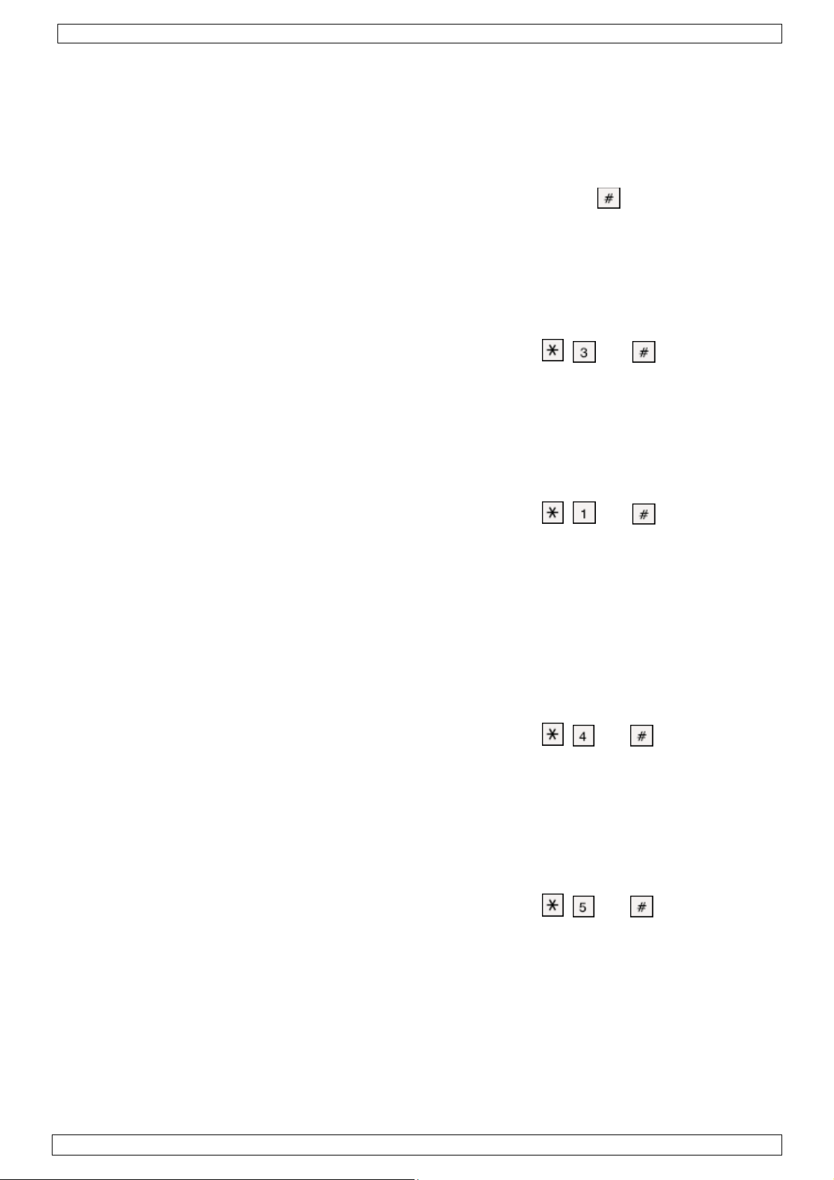
HAA263D
37
• Es ertönen fünf Beeps, um anzuzeigen, dass der Code falsch eingegeben wurde. Geben Sie den
Code korrekt ein.
• Die LEDs der weggelassenen Bereiche blinken ständig.
Das Alarmsystem schaltet ein nachdem die Verzögerung vergangen ist. Die LED der
•
entsprechenden Partition und von EXIT/ARMED leuchtet.
• Die manuell weggelassenen Bereiche werden nach Deaktivierung des Systems gelöscht.
f. Das Alarmsystem abschalten
Geben Sie einfach den korrekten BENUTZERCODE ein und drücken Sie ehe die
•
Einschaltverzögerung vergangen ist.
• Das Alarmsystem wird sofort abgeschaltet.
• Es ertönen zwei Beeps, um anzuzeigen, dass der Code korrekt eingegeben wurde.
• Es ertönen fünf Beeps, um anzuzeigen, dass der Code falsch eingegeben wurde. Geben Sie den
Code nach den Beeps korrekt ein.
g.Den Speicher löschen
Löschen Sie den Speicher, ehe Sie das Alarmsystem einschalten.
• Geben Sie den korrekten BENUTZERCODE ein und drücken Sie , und .
• Alle LEDs der Bereiche erlöschen.
• Das Alarmsystem wurde deaktiviert und kann in jedem Moment wieder eingeschaltet werden.
h.Die Paniktaste
Halten Sie ZWEI Tasten gleichzeitig und mehr als drei Sekunden gedrückt, um den Alarm zu aktivieren.
Das Notsignal ist ein Softwarealarm, angezeigt als Bereich 8, und kann nicht geändert werden.
i.Die defekten Bereiche kontrollieren
• Schalten Sie das Alarmsystem oder die Partition ab.
• Geben Sie den korrekten BENUTZERCODE ein und drücken Sie
Die LEDs der defekten Bereiche leuchten.
•
, und .
• Jeder Bereich wird während 30 Sekunden getestet. Nach jedem Test ertönt einen Beep. Drücken
Sie eine Taste innerhalb von 5 Sekunden nach dem Beep, dann startet eine neue Testperiode
von 30 Sekunden. Die Testperiode kann nach Wünsch wieder angefangen werden.
• Das System funktioniert nach 5 Sekunden nach dem Beep wieder normal (wenn keine Taste
gedrückt wird).
• Das Alarmsystem kann während dem Testen nicht eingeschaltet werden und das Bediengerät ist
zeitlich abgeschaltet.
j. Die Batterie prüfen
• Das System testet automatisch die Reservebatterie alle 24 Stunden.
• Möchten Sie die Batterie manuell testen, so deaktivieren Sie zuerst das Alarmsystem.
• Geben Sie den korrekten BENUTZERCODE ein und drücken Sie
LED blinkt.
, und . Die Batterie-
• Ein manueller Batterietest beeinflusst den periodischen Batterietest nicht.
• Der Test dauert von 5 Sekunden bis 2 Minuten, abhängig von der Batterie.
• Führen Sie einen manuellen Batterietest durch wenn Sie eine Batterie eingelegt haben.
k.Die Relaisausgänge prüfen
Sichtbare und hörbare Signale wie Sirene, Blinklicht, usw. Sind mit den Ausgangsrelais verbunden.
Ein periodischer Test dieser Ausgänge gewährleistet ein gutes Funktionieren.
• Möchten Sie die Ausgänge manuell prüfen, so deaktivieren Sie zuerst das Alarmsystem.
• Geben Sie den korrekten BENUTZERCODE ein und drücken Sie
, und .
• Die Ausgänge für das Timing und den Schloss werden während 5 Sekunden aktiviert. Überprüfen
Sie, ob alle s
ichtbaren und hörbaren Signale wie Sirene, Blinklicht, usw. korrekt funktionieren.
• Überprüfen Sie den Anschluss eines defekten Signals sofort.
• Führen Sie einen monatlichen Test der Ausgänge durch.
9. Technische Daten
Spannung 12 VDC (über das HAM263D)
Abmessungen 117 x 117 x 27 mm
Gewicht 220 g
02 (15/11/2013) VELLEMAN
Page 38

HAA263D
38
Verwenden Sie dieses Gerät nur mit originellen Zubehörteilen. Velleman NV übernimmt
keine Haftung für Schaden oder Verletzungen bei (falscher) Anwendung dieses Gerätes.
Für mehr Informationen zu diesem Produkt, siehe www.velleman.eu. Alle Änderungen
ohne vorherige Ankündigung vorbehalten.
02 (15/11/2013) VELLEMAN
Page 39

Velleman® Service and Quality Warranty
Since its foundation in 1972, Velleman® acquired extensive
experience in the electronics world and currently distributes its
products in over 85 countries.
All our products fulfil strict quality requirements and legal stipulations
in the EU. In order to ensure the quality, our products regularly go
through an extra quality check, both by an internal quality
department and by specialized external organisations. If, all
precautionary measures notwithstanding, problems should occur,
please make appeal to our warranty (see guarantee conditions).
General Warranty Conditions Concerning Consumer Products
(for EU):
• All consumer products are subject to a 24-month warranty on
production flaws and defective material as from the original date of
purchase.
• Velleman® can decide to replace an article with an equivalent
article, or to refund the retail value totally or partially when the
complaint is valid and a free repair or replacement of the article is
impossible, or if the expenses are out of proportion.
You will be delivered a replacing article or a refund at the value of
100% of the purchase price in case of a flaw occurred in the first
year after the date of purchase and delivery, or a replacing article at
50% of the purchase price or a refund at the value of 50% of the
retail value in case of a flaw occurred in the second year after the
date of purchase and delivery.
• Not covered by warranty:
- all direct or indirect damage caused after delivery to the article
(e.g. by oxidation, shocks, falls, dust, dirt, humidity...), and by the
article, as well as its contents (e.g. data loss), compensation for loss
of profits;
- consumable goods, parts or accessories that are subject to an aging
process during normal use, such as batteries (rechargeable, nonrechargeable, built-in or replaceable), lamps, rubber parts, drive
belts... (unlimited list);
- flaws resulting from fire, water damage, lightning, accident, natural
disaster, etc.…;
- flaws caused deliberately, negligently or resulting from improper
handling, negligent maintenance, abusive use or use contrary to the
manufacturer’s instructions;
- damage caused by a commercial, professional or collective use of
the article (the warranty validity will be reduced to six (6) months
when the article is used professionally);
- damage resulting from an inappropriate packing and shipping of the
article;
- all damage caused by modification, repair or alteration performed
by a third party without written permission by Velleman®.
• Articles to be repaired must be delivered to your Velleman® dealer,
solidly packed (preferably in the original packaging), and be
completed with the original receipt of purchase and a clear flaw
description.
• Hint: In order to save on cost and time, please reread the manual
and check if the flaw is caused by obvious causes prior to presenting
the article for repair. Note that returning a non-defective article can
also involve handling costs.
• Repairs occurring after warranty expiration are subject to shipping
costs.
• The above conditions are without prejudice to all commercial
warranties.
The above enumeration is subject to modification according to
the article (see article’s manual).
Velleman® service- en kwaliteitsgarantie
Velleman® heeft sinds zijn oprichting in 1972 een ruime ervaring
opgebouwd in de elektronicawereld en verdeelt op dit moment
producten in meer dan 85 landen. Al onze producten beantwoorden
aan strikte kwaliteitseisen en aan de wettelijke bepalingen geldig in
de EU. Om de kwaliteit te waarborgen, ondergaan onze producten op
regelmatige tijdstippen een extra kwaliteitscontrole, zowel door onze
eigen kwaliteitsafdeling als door externe gespecialiseerde
organisaties. Mocht er ondanks deze voorzorgen toch een probleem
optreden, dan kunt u steeds een beroep doen op onze waarborg (zie
waarborgvoorwaarden).
Algemene waarborgvoorwaarden consumentengoederen
(voor Europese Unie):
• Op alle consumentengoederen geldt een garantieperiode van 24
maanden op productie- en materiaalfouten en dit vanaf de
oorspronkelijke aankoopdatum.
• Indien de klacht gegrond is en een gratis reparatie of vervanging
van een artikel onmogelijk is of indien de kosten hiervoor buiten
verhouding zijn, kan Velleman® beslissen het desbetreffende artikel
te vervangen door een gelijkwaardig artikel of de aankoopsom van
het artikel gedeeltelijk of volledig terug te betalen. In dat geval krijgt
u een vervangend product of terugbetaling ter waarde van 100% van
de aankoopsom bij ontdekking van een gebrek tot één jaar na
aankoop en levering, of een vervangend product tegen 50% van de
kostprijs of terugbetaling van 50 % bij ontdekking na één jaar tot 2
jaar.
• Valt niet onder waarborg:
- alle rechtstreekse of onrechtstreekse schade na de levering
veroorzaakt aan het toestel (bv. door oxidatie, schokken, val, stof,
vuil, vocht...), en door het toestel, alsook zijn inhoud (bv. verlies van
data), vergoeding voor eventuele winstderving.
- verbruiksgoederen, onderdelen of hulpstukken die onderhevig zijn
aan veroudering door normaal gebruik zoals bv. batterijen (zowel
oplaadbare als niet-oplaadbare, ingebouwd of vervangbaar), lampen,
rubberen onderdelen, aandrijfriemen... (onbeperkte lijst).
- defecten ten gevolge van brand, waterschade, bliksem, ongevallen,
natuurrampen, enz.
- defecten veroorzaakt door opzet, nalatigheid of door een
onoordeelkundige behandeling, slecht onderhoud of abnormaal
gebruik of gebruik van het toestel strijdig met de voorschriften van
de fabrikant.
- schade ten gevolge van een commercieel, professioneel of collectief
gebruik van het apparaat (bij professioneel gebruik wordt de
garantieperiode herleid tot 6 maand).
- schade veroorzaakt door onvoldoende bescherming bij transport
van het apparaat.
- alle schade door wijzigingen, reparaties of modificaties uitgevoerd
door derden zonder toestemming van Velleman®.
• Toestellen dienen ter reparatie aangeboden te worden bij uw
Velleman®-verdeler. Het toestel dient vergezeld te zijn van het
oorspronkelijke aankoopbewijs. Zorg voor een degelijke verpakking
(bij voorkeur de originele verpakking) en voeg een duidelijke
foutomschrijving bij.
• Tip: alvorens het toestel voor reparatie aan te bieden, kijk nog
eens na of er geen voor de hand liggende reden is waarom het
toestel niet naar behoren werkt (zie handleiding). Op deze wijze kunt
u kosten en tijd besparen. Denk eraan dat er ook voor niet-defecte
toestellen een kost voor controle aangerekend kan worden.
• Bij reparaties buiten de waarborgperiode zullen transportkosten
aangerekend worden.
• Elke commerciële garantie laat deze rechten onverminderd.
Bovenstaande opsomming kan eventueel aangepast worden
naargelang de aard van het product (zie handleiding van het
betreffende product).
Garantie de service et de qualité Velleman®
Depuis 1972, Velleman® a gagné une vaste expérience dans le
secteur de l’électronique et est actuellement distributeur dans plus de
85 pays.
Tous nos produits répondent à des exigences de qualité rigoureuses
et à des dispositions légales en vigueur dans l’UE. Afin de garantir la
qualité, nous soumettons régulièrement nos produits à des contrôles
de qualité supplémentaires, tant par notre propre service qualité que
par un service qualité externe. Dans le cas improbable d’un défaut
malgré toutes les précautions, il est possible d’invoquer notre
garantie (voir les conditions de garantie).
Conditions générales concernant la garantie sur les produits
grand public (pour l’UE) :
• tout produit grand public est garanti 24 mois contre tout vice de
production ou de matériaux à dater du jour d’acquisition effective ;
• si la plainte est justifiée et que la réparation ou le remplacement
d’un article est jugé impossible, ou lorsque les coûts s’avèrent
disproportionnés, Velleman® s’autorise à remplacer ledit article par
un article équivalent ou à rembourser la totalité ou une partie du prix
d’achat. Le cas échéant, il vous sera consenti un article de
remplacement ou le remboursement complet du prix d’achat lors
d’un défaut dans un délai de 1 an après l’achat et la livraison, ou un
article de remplacement moyennant 50% du prix d’achat ou le
remboursement de 50% du prix d’achat lors d’un défaut après 1 à 2
ans.
• sont par conséquent exclus :
- tout dommage direct ou indirect survenu à l’article après livraison
(p.ex. dommage lié à l’oxydation, choc, chute, poussière, sable,
impureté…) et provoqué par l’appareil, ainsi que son contenu (p.ex.
perte de données) et une indemnisation éventuelle pour perte de
revenus ;
- toute pièce ou accessoire nécessitant un remplacement causé par
un usage normal comme p.ex. piles (rechargeables comme non
rechargeables, intégrées ou remplaçables), ampoules, pièces en
caoutchouc, courroies… (liste illimitée) ;
- tout dommage qui résulte d’un incendie, de la foudre, d’un
accident, d’une catastrophe naturelle, etc. ;
- out dommage provoqué par une négligence, volontaire ou non, une
utilisation ou un entretien incorrect, ou une utilisation de l’appareil
contraire aux prescriptions du fabricant ;
- tout dommage à cause d’une utilisation commerciale,
professionnelle ou collective de l’appareil (la période de garantie sera
réduite à 6 mois lors d’une utilisation professionnelle) ;
- tout dommage à l’appareil qui résulte d’une utilisation incorrecte ou
différente que celle pour laquelle il a été initialement prévu comme
décrit dans la notice ;
- tout dommage engendré par un retour de l’appareil emballé dans
un conditionnement non ou insuffisamment protégé.
- toute réparation ou modification effectuée par une tierce personne
sans l’autorisation explicite de SA Velleman® ; - frais de transport de
et vers Velleman® si l’appareil n’est plus couvert sous la garantie.
• toute réparation sera fournie par l’endroit de l’achat. L’appareil doit
nécessairement être accompagné du bon d’achat d’origine et être
dûment conditionné (de préférence dans l’emballage d’origine avec
mention du défaut) ;
• tuyau : il est conseillé de consulter la notice et de contrôler câbles,
piles, etc. avant de retourner l’appareil. Un appareil retourné jugé
défectueux qui s’avère en bon état de marche pourra faire l’objet
d’une note de frais à charge du consommateur ;
• une réparation effectuée en-dehors de la période de garantie fera
l’objet de frais de transport ;
• toute garantie commerciale ne porte pas atteinte aux conditions
susmentionnées.
La liste susmentionnée peut être sujette à une
complémentation selon le type de l’article et être mentionnée
dans la notice d’emploi.
Page 40

Garantía de servicio y calidad Velleman®
Desde su fundación en 1972 Velleman® ha adquirido una amplia
experiencia como distribuidor en el sector de la electrónica en más de
85 países. Todos nuestros productos responden a normas de calidad
rigurosas y disposiciones legales vigentes en la UE. Para garantizar la
calidad, sometemos nuestros productos regularmente a controles de
calidad adicionales, tanto a través de nuestro propio servicio de
calidad como de un servicio de calidad externo. En el caso
improbable de que surgieran problemas a pesar de todas las
precauciones, es posible recurrir a nuestra garantía (véase las
condiciones de garantía).
Condiciones generales referentes a la garantía sobre
productos de venta al público (para la Unión Europea):
• Todos los productos de venta al público tienen un perìodo de
garantía de 24 meses contra errores de producción o errores en
materiales desde la adquisición original;
• Si la queja está fundada y si la reparación o sustitución de un
artículo no es posible, o si los gastos son desproporcionados,
Velleman® autoriza reemplazar el artículo por un artículo equivalente
o reembolsar la totalidad o una parte del precio de compra. En este
caso, usted recibirá un artículo de recambio o el reembolso completo
del precio de compra si encuentra algún fallo hasta un año después
de la compra y entrega, o un artículo de recambio al 50% del precio
de compra o el reembolso del 50% del precio de compra si encuentra
un fallo después de 1 año y hasta los 2 años después de la compra y
entrega.
Por consiguiente, están excluidos entre otras cosas:
- todos los daños causados directa o indirectamente al aparato (p.ej.
por oxidación, choques, caída,...) y a su contenido (p.ej. pérdida de
datos) después de la entrega y causados por el aparato, y cualquier
indemnización por posible pérdida de ganancias;
- partes o accesorios, que estén expuestos al desgaste causado por
un uso normal, como por ejemplo baterías (tanto recargables como
no recargables, incorporadas o reemplazables), bombillas, partes de
goma, etc. (lista ilimitada);
- defectos causados por un incendio, daños causados por el agua,
rayos, accidentes, catástrofes naturales, etc.;
- defectos causados a conciencia, descuido o por malos tratos, un
mantenimiento inapropiado o un uso anormal del aparato contrario a
las instrucciones del fabricante;
- daños causados por un uso comercial, profesional o colectivo del
aparato (el período de garantía se reducirá a 6 meses con uso
profesional);
- daños causados por un uso incorrecto o un uso ajeno al que está
previsto el producto inicialmente como está descrito en el manual del
usuario;
- daños causados por una protección insuficiente al transportar el
aparato.
- daños causados por reparaciones o modificaciones efectuadas por
una tercera persona sin la autorización explícita de Velleman®;
- se calcula gastos de transporte de y a Velleman® si el aparato ya
no está cubierto por la garantía.
• Cualquier artìculo que tenga que ser reparado tendrá que ser
devuelto a su distribuidor Velleman®. Devuelva el aparato con la
factura de compra original y transpórtelo en un embalaje sólido
(preferentemente el embalaje original). Incluya también una buena
descripción del fallo;
• Consejo: Lea el manual del usuario y controle los cables, las pilas,
etc. antes de devolver el aparato. Si no se encuentra un defecto en el
artículo los gastos podrían correr a cargo del cliente;
• Los gastos de transporte correrán a carga del cliente para una
reparación efectuada fuera del período de garantía.
• Cualquier gesto comercial no disminuye estos derechos.
La lista previamente mencionada puede ser adaptada según el
tipo de artículo (véase el manual del usuario del artículo en
cuestión).
Velleman® Service- und Qualitätsgarantie
Seit der Gründung in 1972 hat Velleman® sehr viel Erfahrung als
Verteiler in der Elektronikwelt in über 85 Ländern aufgebaut.
Alle Produkte entsprechen den strengen Qualitätsforderungen und
gesetzlichen Anforderungen in der EU. Um die Qualität zu
gewährleisten werden unsere Produkte regelmäßig einer zusätzlichen
Qualitätskontrolle unterworfen, sowohl von unserer eigenen
Qualitätsabteilung als auch von externen spezialisierten
Organisationen. Sollten, trotz aller Vorsichtsmaßnahmen, Probleme
auftreten, nehmen Sie bitte die Garantie in Anspruch (siehe
Garantiebedingungen).
Allgemeine Garantiebedingungen in Bezug auf Konsumgüter
(für die Europäische Union):
• Alle Produkte haben für Material- oder Herstellungsfehler eine
Garantieperiode von 24 Monaten ab Verkaufsdatum.
• Wenn die Klage berechtigt ist und falls eine kostenlose Reparatur
oder ein Austausch des Gerätes unmöglich ist, oder wenn die Kosten
dafür unverhältnismäßig sind, kann Velleman® sich darüber
entscheiden, dieses Produkt durch ein gleiches Produkt zu ersetzen
oder die Kaufsumme ganz oder teilweise zurückzuzahlen. In diesem
Fall erhalten Sie ein Ersatzprodukt oder eine Rückzahlung im Werte
von 100% der Kaufsumme im Falle eines Defektes bis zu 1 Jahr nach
Kauf oder Lieferung, oder Sie bekommen ein Ersatzprodukt im Werte
von 50% der Kaufsumme oder eine Rückzahlung im Werte von 50 %
im Falle eines Defektes im zweiten Jahr.
• Von der Garantie ausgeschlossen sind:
- alle direkten oder indirekten Schäden, die nach Lieferung am Gerät
und durch das Gerät verursacht werden (z.B. Oxidation, Stöße, Fall,
Staub, Schmutz, Feuchtigkeit, ...), sowie auch der Inhalt (z.B.
Datenverlust), Entschädigung für eventuellen Gewinnausfall.
- Verbrauchsgüter, Teile oder Zubehörteile, die durch normalen
Gebrauch dem Verschleiß ausgesetzt sind, wie z.B. Batterien (nicht
nur aufladbare, sondern auch nicht aufladbare, eingebaute oder
ersetzbare), Lampen, Gummiteile, Treibriemen, usw. (unbeschränkte
Liste).
- Schäden verursacht durch Brandschaden, Wasserschaden, Blitz,
Unfälle, Naturkatastrophen, usw.
- Schäden verursacht durch absichtliche, nachlässige oder
unsachgemäße Anwendung, schlechte Wartung, zweckentfremdete
Anwendung oder Nichtbeachtung von Benutzerhinweisen in der
Bedienungsanleitung.
- Schäden infolge einer kommerziellen, professionellen oder
kollektiven Anwendung des Gerätes (bei gewerblicher Anwendung
wird die Garantieperiode auf 6 Monate zurückgeführt).
- Schäden verursacht durch eine unsachgemäße Verpackung und
unsachgemäßen Transport des Gerätes.
- alle Schäden verursacht durch unautorisierte Änderungen,
Reparaturen oder Modifikationen, die von einem Dritten ohne
Erlaubnis von Velleman® vorgenommen werden.
• Im Fall einer Reparatur, wenden Sie sich an Ihren Velleman®Verteiler. Legen Sie das Produkt ordnungsgemäß verpackt
(vorzugsweise die Originalverpackung) und mit dem OriginalKaufbeleg vor. Fügen Sie eine deutliche Fehlerbeschreibung hinzu.
• Hinweis: Um Kosten und Zeit zu sparen, lesen Sie die
Bedienungsanleitung nochmals und überprüfen Sie, ob es keinen auf
de Hand liegenden Grund gibt, ehe Sie das Gerät zur Reparatur
zurückschicken. Stellt sich bei der Überprüfung des Gerätes heraus,
dass kein Geräteschaden vorliegt, könnte dem Kunden eine
Untersuchungspauschale berechnet.
• Für Reparaturen nach Ablauf der Garantiefrist werden
Transportkosten berechnet.
• Jede kommerzielle Garantie lässt diese Rechte unberührt.
Die oben stehende Aufzählung kann eventuell angepasst
werden gemäß der Art des Produktes (siehe
Bedienungsanleitung des Gerätes).
Legen Heirweg 33, 9890 Gavere, Belgium
Imported by Velleman nv
Made in PRC
www.velleman.eu
 Loading...