

Page 1
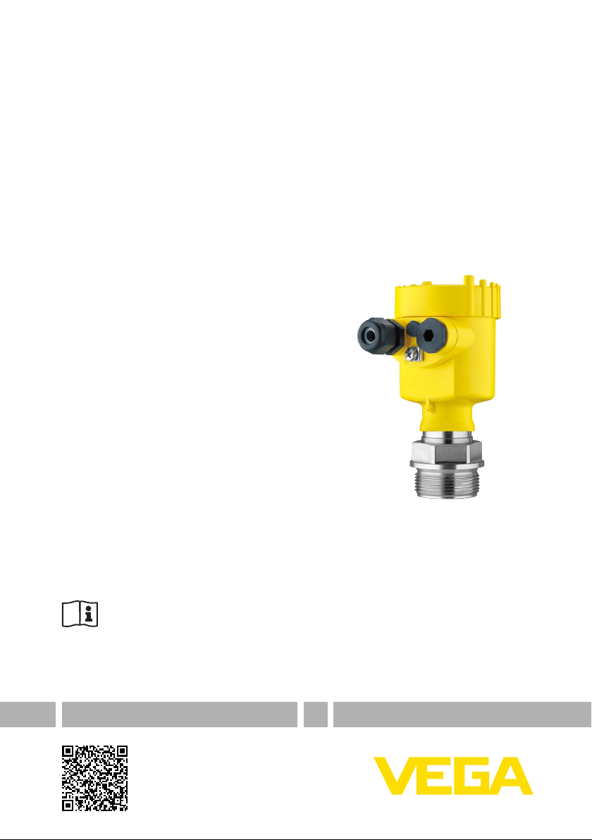
Safety Manual
VEGABAR series 80
Two-wire 4 … 20 mA/HART
and Secondary sensors
With SIL qualication
Document ID: 48369
Page 2

Contents
Contents
1 Document language ................................................................................................................ 3
2 Scope ........................................................................................................................................ 4
2.1 Instrument version ............................................................................................................ 4
2.2 Application area ............................................................................................................... 4
2.3 SIL conformity .................................................................................................................. 5
3 Planning .................................................................................................................................... 6
3.1 Safety function ................................................................................................................. 6
3.2 Safe state ......................................................................................................................... 6
3.3 Prerequisites for operation ............................................................................................... 6
4 Safety-related characteristics................................................................................................. 7
4.1 Characteristics acc. to IEC 61508 for process pressure measurement or hydrostatic level
measurement ................................................................................................................... 7
4.2 Characteristics acc. to IEC 61508 for applications with Secondary sensor ...................... 8
4.3 Characteristics acc. to ISO 13849-1 for process pressure measurement or hydrostatic
level measurement ......................................................................................................... 10
4.4 Characteristics acc. to ISO 13849-1 for applications with Secondary sensor ................. 11
4.5 Supplementary information ............................................................................................ 12
5 Setup ....................................................................................................................................... 13
5.1 General information ........................................................................................................ 13
5.2 Instrument parameter adjustment ................................................................................... 13
6 Diagnostics and servicing .................................................................................................... 15
6.1 Behaviour in case of failure ............................................................................................ 15
6.2 Repair ............................................................................................................................ 15
7 Proof test ................................................................................................................................ 16
7.1 General information ........................................................................................................ 16
7.2 Test 1: Without checking the process variable ................................................................ 16
7.3 Test 2: With check of the process variable ...................................................................... 17
8 Appendix A: Test report ......................................................................................................... 18
9 AppendixB:Termdenitions ................................................................................................ 19
10 Supplement C: SIL conformity .............................................................................................. 20
48369-EN-210114
Editing status: 2020-12-18
2
VEGABAR series 80 • Two-wire 4 … 20 mA/HART
Page 3

1 Document language
1 Document language
DE Das vorliegende Safety Manual für Funktionale Sicherheit ist verfügbar in den Sprachen
EN The current Safety Manual for Functional Safety is available in German, English, French and
FR Le présent Safety Manual de sécurité fonctionnelle est disponible dans les langues suivantes:
RU Данное руководство по функциональной безопасности Safety Manual имеется на
Deutsch, Englisch, Französisch und Russisch.
Russian language.
allemand, anglais, français et russe.
немецком, английском, французском и русском языках.
48369-EN-210114
VEGABAR series 80 • Two-wire 4 … 20 mA/HART
3
Page 4

2 Scope
2 Scope
2.1 Instrument version
This safety manual applies to pressure transmitters
VEGABAR 81, 82, 83, 86, 87
VEGABAR 81, 82, 83, 86, 87 Secondary-Sensor
Electronics types:
Two-wire 4 … 20 mA/HART with SIL qualication
•
Two-wire 4 … 20 mA/HART with SIL qualication and supplemen-
•
tary electronics "Additional current output 4 … 20 mA"
Secondary electronics for electronic dierential pressure with SIL
•
qualication
Valid versions:
from HW Ver 1.0.0
•
from SW Ver 1.0.0
•
Secondary electronics from HW Ver 1.0.0
•
The climate-compensated versions are excluded from safety-relevant
applications!
2.2 Application area
The pressure transmitter can be used in a safety-related system
according to IEC 61508 in the modes low demand mode or high de-
mand mode for the measurement of the following process variables:
Process pressure measurement
•
Hydrostatic level measurement
•
With Secondary sensor:
Dierential pressure measurement
•
Flow measurement
•
Density measurement
•
Interface measurement
•
Due to the systematic capability SC3 this is possible up to:
SIL2 in single-channel architecture
•
SIL3 in multiple channel architecture
•
The following interface can be used to output the measured value:
Current output: 4 … 20 mA
•
The following interfaces are only permitted for parameter adjustment
and for informative use:
HART
•
Display and adjustment module PLICSCOM (also via Bluetooth)
•
VEGACONNECT (also via Bluetooth)
•
Current output II
•
1)
48369-EN-210114
1)
Only with instrument version with supplementary electronics "Additional cur-
rent output 4 … 20 mA".
4
VEGABAR series 80 • Two-wire 4 … 20 mA/HART
Page 5

2 Scope
2.3 SIL conformity
The SIL conrmity was judged and certied independently by TÜV
Rheinland according to IEC 61508:2010 (Ed.2) (verication docu-
ments see " Supplement").
The certicate is valid for the entire service life of all instruments that
were sold before the certicate expired!
48369-EN-210114
VEGABAR series 80 • Two-wire 4 … 20 mA/HART
5
Page 6
3 Planning
Safety function
3 Planning
3.1 Safety function
The transmitter generates on its current output a signal between
3.8 mA and 20.5 mA corresponding to the process variable. This
analogue signal is fed to a connected processing system to monitor
the following conditions:
Exceeding a dened limit value of the process variable
•
Falling below a dened limit value of the process variable
•
Monitoring of a dened range of the process variable
•
Safety tolerance
Safe state
Fault signals in case of
malfunction
Instructions and restrictions
For the design of the safety function, the following aspects must be
taken into account with regard to the tolerances:
Due to undetected failures in the range between 3.8 mA and
•
20.5 mA, an incorrect output signal can be generated which deviates from the real measured value by up to 2 %
Due to the special application conditions, increased measurement
•
deviations can be caused (see Technical data in the operating
instructions)
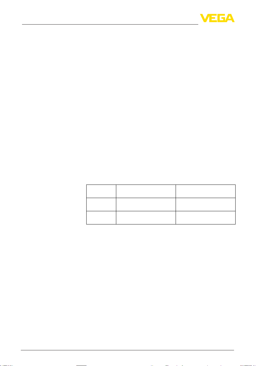
3.2 Safe state
The safe state of the current output depends on the safety function
and the characteristics set on the sensor.
Characteristics
4 … 20 mA Output current ≥ Switching
20 … 4 mA Output current ≤ Switching
Possible fault currents:
≤ 3.6 mA ("fail low")
•
> 21 mA ("fail high")
•
Monitoring upper limit val-ueMonitoring lower limit value
point
point
Output current ≤ Switching
point
Output current ≥ Switching
point
3.3 Prerequisites for operation
The measuring system should be used appropriately taking pres-
•
sure, temperature, density and chemical properties of the medium
into account. The application-specic limits must be observed.
The specications according to the operating instructions manual,
•
particularly the current load on the output circuits, must be kept
within the specied limits
Existing communication interfaces (e. g. HART, USB) are not used
•
for transmission of the safety-relevant measured value
The instructions in chapter " Safety-related characteristics", para-
•
graph " Supplementary information" must be noted
All parts of the measuring chain must correspond to the planned "
•
Safety Integrity Level (SIL)"
48369-EN-210114
6
VEGABAR series 80 • Two-wire 4 … 20 mA/HART
Page 7
VEGABAR 82, 83, 86, 87
4 Safety-related characteristics
4 Safety-related characteristics
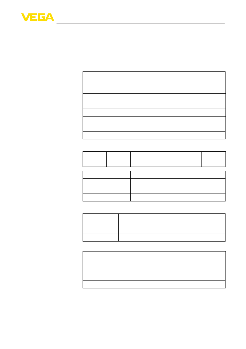
4.1 Characteristics acc. to IEC 61508 for process pressure measurement or hydrostatic level measurement
Parameter Value
Safety Integrity Level SIL2 in single-channel architecture
SIL3 in multiple channel architecture 2)
Hardware fault tolerance HFT = 0
Instrument type Type B
Mode Low demand mode, High demand mode
SFF > 90 %
MTBF 3) 0.50 x 10⁶ h (57 years)
Diagnostic test interval 4) < 30 min
Failure rates
λ
S
0 FIT 1121 FIT 44 FIT 9 FIT 59 FIT 34 FIT
λ
DD
λ
DU
λ
H
λ
L
λ
AD
PFD
AVG
PFD
AVG
PFD
AVG
PFH 0.044 x 10⁻⁶ 1/h
Proof Test Coverag (PTC)
Test type 5)
Test 1 21 FIT 52 %
Test 2 2 FIT 95 %
VEGABAR 81
Parameter Value
Safety Integrity Level SIL2 in single-channel architecture
Hardware fault tolerance HFT = 0
Instrument type Type B
2)
Homogeneous redundancy possible, because systematic capability SC3.
3)
Including errors outside the safety function.
4)
Time during which all internal diagnoses are carried out at least once.
5)
See section "Proof test".
6)
48369-EN-210114
VEGABAR series 80 • Two-wire 4 … 20 mA/HART
Homogeneous redundancy possible, because systematic capability SC3.
0.037 x 10
0.054 x 10
0.106 x 10
-2
-2
-2
(T1 = 1 year)
(T1 = 2 years)
(T1 = 5 years)
Remaining failure rate of dangerous undetected failures
SIL3 in multiple channel architecture 6)
PTC
7
Page 8
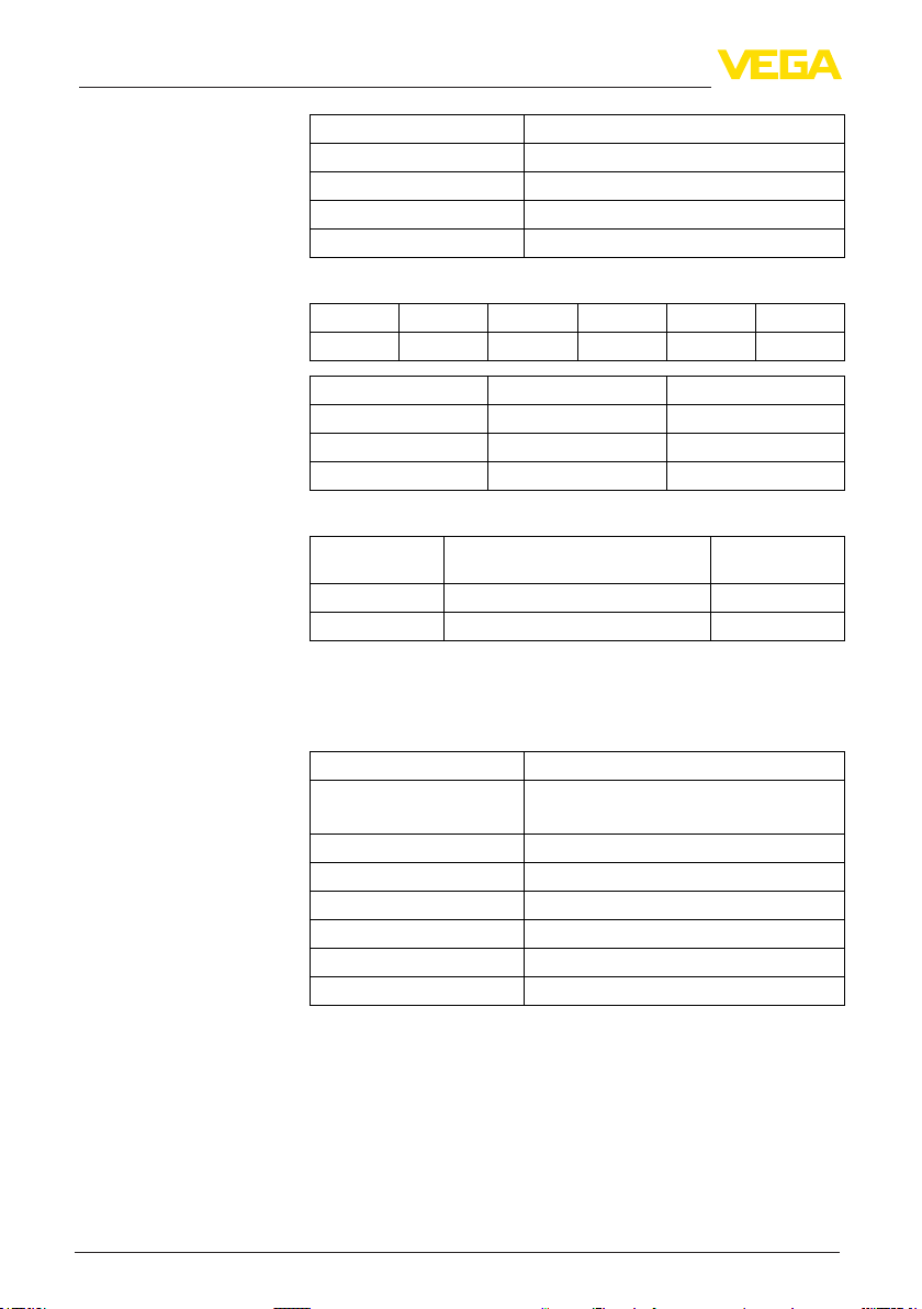
4 Safety-related characteristics
Parameter Value
Mode Low demand mode, High demand mode
SFF > 90 %
MTBF 7) 0.57 x 10⁶ h (65 years)
Diagnostic test interval 8) < 30 min
Failure rates
λ
S
0 FIT 981 FIT 77 FIT 9 FIT 59 FIT 34 FIT
λ
DD
λ
DU
λ
H
λ
L
λ
AD
Device combination consisting of VEGABAR 82,
83, 86 or 87
PFD
PFD
PFD
AVG
AVG
AVG
0.065 x 10
0.096 x 10
0.188 x 10
-2
-2
-2
(T1 = 1 year)
(T1 = 2 years)
(T1 = 5 years)
PFH 0.077 x 10⁻⁶ 1/h
Proof Test Coverag (PTC)
Test type 9)
Test 1 56 FIT 28 %
Test 2 2 FIT 97 %
Remaining failure rate of dangerous undetected failures
PTC
4.2 Characteristics acc. to IEC 61508 for applications with Secondary sensor
Parameter Value
Safety Integrity Level SIL2 in single-channel architecture
SIL3 in multiple channel architecture
Hardware fault tolerance HFT = 0
Instrument type Type B
Mode Low demand mode, High demand mode
SFF > 90 %
11)
MTBF
0.39 x 10⁶ h (44 years)
Diagnostic test interval
12)
< 30 min
10)
48369-EN-210114
7)
Including errors outside the safety function.
8)
Time during which all internal diagnoses are carried out at least once.
9)
See section "Proof test".
10)
Homogeneous redundancy possible, because systematic capability SC3.
11)
Including errors outside the safety function.
12)
Time during which all internal diagnoses are carried out at least once.
8
VEGABAR series 80 • Two-wire 4 … 20 mA/HART
Page 9

4 Safety-related characteristics
Failure rates
λ
S
0 FIT 1406 FIT 63 FIT 9 FIT 59 FIT 34 FIT
λ
DD
λ
DU
λ
H
λ
L
λ
AD
Device combination consisting of a VEGABAR 81
and a VEGABAR 82, 83,
86 or 87
PFD
PFD
PFD
AVG
AVG
AVG
0.054 x 10
0.079 x 10
0.154 x 10
-2
-2
-2
(T1 = 1 year)
(T1 = 2 years)
(T1 = 5 years)
PFH 0.063 x 10⁻⁶ 1/h
Proof Test Coverag (PTC)
Remaining failure rate of danger-
Test type
13)
ous undetected failures
PTC
Test 1 40 FIT 36 %
Test 2 3 FIT 95 %
Parameter Value
Safety Integrity Level SIL2 in single-channel architecture
SIL3 in multiple channel architecture
Hardware fault tolerance HFT = 0
Instrument type Type B
Mode Low demand mode, High demand mode
SFF > 90 %
15)
MTBF
0.43 x 10⁶ h (50 years)
Diagnostic test interval
16)
< 30 min
Failure rates
λ
S
0 FIT 1266 FIT 97 FIT 9 FIT 59 FIT 34 FIT
λ
DD
λ
DU
λ
H
λ
L
14)
λ
AD
PFD
AVG
PFD
AVG
PFD
AVG
PFH 0.097 x 10⁻⁶ 1/h
13)
See section "Proof test".
14)
Homogeneous redundancy possible, because systematic capability SC3.
15)
Including errors outside the safety function.
16)
48369-EN-210114
Time during which all internal diagnoses are carried out at least once.
VEGABAR series 80 • Two-wire 4 … 20 mA/HART
0.082 x 10
0.120 x 10
0.235 x 10
-2
-2
-2
(T1 = 1 year)
(T1 = 2 years)
(T1 = 5 years)
9
Page 10

4 Safety-related characteristics
Device combination consisting of VEGABAR 81
Proof Test Coverag (PTC)
Remaining failure rate of danger-
Test type
17)
ous undetected failures
PTC
Test 1 75 FIT 22 %
Test 2 3 FIT 97 %
Parameter Value
Safety Integrity Level SIL2 in single-channel architecture
SIL3 in multiple channel architecture
Hardware fault tolerance HFT = 0
Instrument type Type B
Mode Low demand mode, High demand mode
SFF > 90 %
19)
MTBF
0.49 x 10⁶ h (56 years)
Diagnostic test interval
20)
< 30 min
Failure rates
λ
S
0 FIT 1124 FIT 132 FIT 9 FIT 59 FIT 34 FIT
λ
DD
λ
DU
λ
H
λ
L
18)
λ
AD
10
PFD
PFD
PFD
AVG
AVG
AVG
0.111 x 10
0.163 x 10
0.320 x 10
-2
-2
-2
(T1 = 1 year)
(T1 = 2 years)
(T1 = 5 years)
PFH 0.132 x 10⁻⁶ 1/h
Proof Test Coverag (PTC)
Remaining failure rate of danger-
Test type
21)
ous undetected failures
PTC
Test 1 110 FIT 16 %
Test 2 4 FIT 97 %
4.3 Characteristics acc. to ISO 13849-1 for process pressure measurement or hydrostatic level measurement
The transmitter has been manufactured and veried using principles
that demonstrate its suitability and reliability for safety-related applications. It can therefore be considered a " proven component" according
to DIN EN ISO 13849-1.
17)
See section "Proof test".
18)
Homogeneous redundancy possible, because systematic capability SC3.
19)
Including errors outside the safety function.
20)
Time during which all internal diagnoses are carried out at least once.
21)
See section "Proof test".
VEGABAR series 80 • Two-wire 4 … 20 mA/HART
48369-EN-210114
Page 11

4 Safety-related characteristics
VEGABAR 82, 83, 86, 87
VEGABAR 81
Device combination consisting of VEGABAR 82,
83, 86 or 87
Device combination consisting of a VEGABAR 81
and a VEGABAR 82, 83,
86 or 87
Device combination consisting of VEGABAR 81
Derived from the safety-related characteristics, the following gures
result according to ISO 13849-1 (safety of machinery):
Parameter Value
MTTFd 90 years
DC 97 %
Performance Level 4.35 x 10⁻⁸ 1/h
Parameter Value
MTTFd 98 years
DC 93 %
Performance Level 7.75 x 10⁻⁸ 1/h
22)
4.4 Characteristics acc. to ISO 13849-1 for applications with Secondary sensor
The transmitter has been manufactured and veried using principles
that demonstrate its suitability and reliability for safety-related applications. It can therefore be considered a " proven component" according
to DIN EN ISO 13849-1.
Derived from the safety-related characteristics, the following gures
result according to ISO 13849-1 (safety of machinery):
Parameter Value
MTTFd 73 years
DC 96 %
Performance Level 6.33 x 10⁻⁸ 1/h
Parameter Value
MTTFd 78 years
DC 93 %
Performance Level 9.72 x 10⁻⁸ 1/h
Parameter Value
MTTFd 84 years
DC 90 %
Performance Level 1.32 x 10⁻⁷ 1/h
23)
22)
ISO 13849-1 was not part of the certication of the instrument.
23)
48369-EN-210114
VEGABAR series 80 • Two-wire 4 … 20 mA/HART
ISO 13849-1 was not part of the certication of the instrument.
11
Page 12

4 Safety-related characteristics
PTC × λDU × T1
2
(1 – PTC) × λDU × LT
2
Determination of the
failure rates
Assumptions of the
FMEDA
4.5 Supplementary information
The failure rates of the instruments were determined by an FMEDA
according to IEC 61508. The calculations are based on failure rates of
the components according to SN 29500:
All gures refer to an average ambient temperature of 40 °C (104 °F)
during the operating time. For higher temperatures, the values should
be corrected:
Continuous application temperature > 50 °C (122 °F) by factor 1.3
•
Continuous application temperature > 60 °C (140 °F) by factor 2.5
•
Similar factors apply if frequent temperature uctations are expected.
The failure rates are constant. Take note of the useful service life of
•
the components according to IEC 61508-2.
Multiple failures are not taken into account
•
Wear on mechanical parts is not taken into account
•
Failure rates of external power supplies are not taken into account
•
The environmental conditions correspond to an average industrial
•
environment
Calculation of PFD
Boundary conditions re-
latingtotheconguration
of the processing unit
Multiple channel architecture
AVG
The values for PFD
1oo1 architecture:
PFDAVG = + λDD x MTTR +
Parameters used:
T1 = Proof Test Interval
•
PTC = 90 %
•
LT = 10 years
•
MTTR = 8 h
•
A connected control and processing unit must have the following
properties:
The failure signals of the measuring system are judged according
•
to the idle current principle
" fail low" and " fail high" signals are interpreted as a failure, where-
•
upon the safe state must be taken on
If this is not the case, the respective percentages of the failure rates
must be assigned to the dangerous failures and the values stated in
chapter Safety-related characteristics“ redetermined!
Due to the systematic capability SC3, this instrument can also be
used in multiple channel systems up to SIL3, also with a homogene-
ously redundant conguration.
The safety-related characteristics must be calculated especially for
the selected structure of the measuring chain using the stated failure
rates. In doing this, a suitable Common Cause Factor (CCF) must be
considered (see IEC 61508-6, appendix D).
specied above were calculated as follows for a
AVG
48369-EN-210114
12
VEGABAR series 80 • Two-wire 4 … 20 mA/HART
Page 13

Mounting and installation
Tools
5 Setup
5 Setup
5.1 General information
Take note of the mounting and installation instructions in the operating
instructions manual.
Setup must be carried out under process conditions.
5.2 Instrument parameter adjustment
The following adjustment units are permitted for parameterization of
the safety function:
Display and adjustment module
•
The DTM suitable for VEGABAR 80 in conjunction with an adjust-
•
ment software according to the FDT/DTM standard, e. g. PACTware
The device description EDD suitable for VEGABAR 80
•
The parameter adjustment is described in the operating instructions
manual.
Wireless connection is also possible with existing Bluetooth function.
The documentation of the device settings is only possible with the full
version of the DTM Collection.
Safety-relevant parameters
Safe parameterization
48369-EN-210114
VEGABAR series 80 • Two-wire 4 … 20 mA/HART
For protection against unwanted or unauthorzed adjustment, the set
parameters must be protected against unauthorized access. For this
reason, the instrument is shipped in locked condition. The PIN in
delivery status is "0000".
The default values of the parameters are listed in the operating
instructions. When shipped with customer-specic parameter settings, the instrument is accompanied by a list of the values diering
from the default values.
By means of the serial number this list can also be downloaded at "
www.vega.com", " Instrument search (serial number)".
To avoid or detect possible errors during parameter adjustment for
unsafe operating environments, a verication procedure is used that
allows the safety-relevant parameters to be checked.
Parameter adjustment proceeds according to the following steps:
Unlock adjustment
•
Change parameters
•
Lock adjustment and verify modied parameters
•
The exact process is described in the operating instructions.
Wireless connection is also possible with existing Bluetooth function.
The instrument is shipped in locked condition!
For verication, all modied, safety-relevant and non safety-relevant
parameters are shown.
13
Page 14

5 Setup
The verication texts are displayed either in German or, when any
other menu language is used, in English.
Unsafe device
status
Instrument reset
Warning:
When adjustment is unlocked, the safety function must be considered
as unreliable. This applies until the parameters are veried and the
adjustment is locked again. If the parameter adjustment process is
not carried out completely, the device statuses described in the operating instructions must be taken into consideration.
If necessary, you must take other measures to maintain the safety
function.
Warning:
In case a reset to " Delivery status" or " Basic setting" is carried out,
all safety-relevant parameters must be checked or set anew.
14
48369-EN-210114
VEGABAR series 80 • Two-wire 4 … 20 mA/HART
Page 15

Internal diagnosis
6 Diagnostics and servicing
6 Diagnostics and servicing
6.1 Behaviour in case of failure
The instrument permanently monitored by an internal diagnostic
system. If a malfunction is detected, a fault signal will be output on the
safety-relevant output (see section " Safe status").
The diagnosis interval is specied in chapter " Safety-related characteristics".
Error messages in case
of malfunction
Electronics exchange
Software update
A fault message coded according to the type of fault is output. The
fault messages are listed in the operating instructions.
If failures are detected, the entire measuring system must be shut
down and the process held in a safe state by other measures.
The occurrence of a failure must be reported to the manufacturer
(including a description of the fault and whether it is a dangerous,
undetected failure). The device must be returned to the manufacturer
for examination.
6.2 Repair
The procedure is described in the operating instructions manual. Note
the instructions for parameter adjustment and setup.
The procedure is described in the operating instructions manual. Note
the instructions for parameter adjustment and setup.
48369-EN-210114
VEGABAR series 80 • Two-wire 4 … 20 mA/HART
15
Page 16

7 Proof test
Objective
Preparation
Unsafe device
status
7 Proof test
7.1 General information
To identify possible dangerous, undetected failures, the safety function must be checked by a proof test at adequate intervals. It is the
user's responsibility to choose the type of testing. The time intervals
are determined by the selected PFD
characteristics").
For documentation of these tests, the test protocol in the appendix
can be used.
If one of the tests proves negative, the entire measuring system must
be switched out of service and the process held in a safe state by
means of other measures.
In a multiple channel architecture this applies separately to each
channel.
Determine safety function (mode, switching points)
•
If necessary, remove the instruments from the safety chain and
•
maintain the safety function by other means
Provide an approved adjustment unit
•
Warning:
During the function test, the safety function must be treated as unreli-
able. Take into account that the function test inuences downstream
connected devices.
If necessary, you must take other measures to maintain the safety
function.
After the function test, the status specied for the safety function must
be restored.
(see chapter " Safety-related
AVG
Conditions
Procedure
Expected result
16
7.2 Test 1: Without checking the process variable
Instrument can remain in installed condition
•
Output signal corresponds to the assigned process variable
•
Device status in the menu Diagnosis: " OK"
•
1. Carry out a re-start (separate the test item at least 10 seconds
from mains voltage)
2. Simulate upper fault current > 21 mA and check current output
(test line resistor)
3. Simulate lower fault current ≤ 3.6 mA and check current output
(test quiescent currents)
Note
Test 1 detects no failures in the probably used Secondary sensor!
Step 1: Output signal corresponds to the assigned process variable
and the device status in the menu Diagnosis is " OK"
Step 2: Output signal corresponds to > 21 mA
Step 3: Output signal corresponds to ≤ 3.6 mA
VEGABAR series 80 • Two-wire 4 … 20 mA/HART
48369-EN-210114
Page 17

7 Proof test
Proof Test Coverage
Conditions
Procedure
Expected result
See Safety-related characteristics
7.3 Test 2: With check of the process variable
Instrument can remain in installed condition
•
Output signal corresponds to the assigned process variable
•
Device status in the menu Diagnosis: " OK"
•
1. Carry out a re-start (separate the test item at least 10 seconds
from mains voltage)
2. Simulate upper fault current > 21 mA and check current output
(test line resistor)
3. Simulate lower fault current ≤ 3.6 mA and check current output
(test quiescent currents)
4. Reference pressure measurement at 0 % - 50 % - 90 … 100 %
of the adjusted measuring range in use (4 mA - 12 mA 18,4 … 20 mA)
5. If necessary, sensor calibration through service log-in and subse-
quent reference pressure measurement as under point 4
Note
When a Secondary sensor is used, also this sensor must be checked
with a reference pressure measurement acc. to point 4!
Step 1: Output signal corresponds to the assigned process variable
and the device status in the menu Diagnosis is " OK"
Step 2: Output signal corresponds to > 21 mA
Step 3: Output signal corresponds to ≤ 3.6 mA
Step 4 and 5: Output signal corresponds to the reference pressure
Proof Test Coverage
48369-EN-210114
VEGABAR series 80 • Two-wire 4 … 20 mA/HART
See Safety-related characteristics
17
Page 18

8 Appendix A: Test report
8 Appendix A: Test report
Identication
Company/Tester
Plant/Instrument TAG
Meas. loop TAG
Instrument type/Order code
Instrument serial number
Date, setup
Date of the last proof test
Test reason/Test scope
Setup without checking the process variable
Setup with check of the process variable
Proof test without checking the process variable
Proof test with check of the process variable
Mode
Monitoring of an upper limit value
Monitoring a lower limit value
Range monitoring
Adjusted parameters of the safety function are documented
Ye s
No
Test result (if necessary)
Test point Process variable
Value 1
Value 2
Value 3
Value 4
Value 5
Conrmation
Date: Signature:
24)
Expected measured
value
24)
e.g.: limit level, level, interface, pressure, ow, density
18
Real value Test result
48369-EN-210114
VEGABAR series 80 • Two-wire 4 … 20 mA/HART
Page 19

Abbreviations
9 Appendix B: Term denitions
9 AppendixB:Termdenitions
SIL Safety Integrity Level (SIL1, SIL2, SIL3, SIL4)
SC Systematic Capability (SC1, SC2, SC3, SC4)
HFT Hardware Fault Tolerance
SFF Safe Failure Fraction
PFD
PFH Average frequency of a dangerous failure per hour (Ed.2)
FMEDA Failure Mode, Eects and Diagnostics Analysis
FIT Failure In Time (1 FIT = 1 failure/109 h)
λ
λ
λ
λ
λ
λ
λ
λ
λ
DC Diagnostic Coverage
PTC Proof Test Coverage (Diagnostic coverage for manual proof tests)
T1 Proof Test Interval
LT Useful Life Time
MTBF Mean Time Between Failure = MTTF + MTTR
MTTF Mean Time To Failure
MTTR IEC 61508, Ed1: Mean Time To Repair
MTTFdMean Time To dangerous Failure (ISO 13849-1)
PL Performance Level (ISO 13849-1)
Average Probability of dangerous Failure on Demand
AVG
Rate for safe detected failure
SD
Rate for safe undetected failure
SU
λS = λSD + λ
S
Rate for dangerous detected failure
DD
Rate for dangerous undetected failure
DU
Rate for failure, who causes a high output current (> 21 mA)
H
Rate for failure, who causes a low output current (≤ 3.6 mA)
L
Rate for diagnostic failure (detected)
AD
Rate for diagnostic failure (undetected)
AU
SU
IEC 61508, Ed2: Mean Time To Restoration
48369-EN-210114
VEGABAR series 80 • Two-wire 4 … 20 mA/HART
19
Page 20

10 Supplement C: SIL conformity
10 Supplement C: SIL conformity
20
48369-EN-210114
VEGABAR series 80 • Two-wire 4 … 20 mA/HART
Page 21

10 Supplement C: SIL conformity
48369-EN-210114
VEGABAR series 80 • Two-wire 4 … 20 mA/HART
21
Page 22

10 Supplement C: SIL conformity
22
48369-EN-210114
VEGABAR series 80 • Two-wire 4 … 20 mA/HART
Page 23

Notes
48369-EN-210114
VEGABAR series 80 • Two-wire 4 … 20 mA/HART
23
Page 24

Printing date:
All statements concerning scope of delivery, application, practical use and operating conditions of the sensors and processing systems correspond to the information
available at the time of printing.
Subject to change without prior notice
© VEGA Grieshaber KG, Schiltach/Germany 2021
VEGA Grieshaber KG
Am Hohenstein 113
77761 Schiltach
Germany
Phone +49 7836 50-0
Fax +49 7836 50-201
E-mail: info.de@vega.com
www.vega.com
48369-EN-210114
 Loading...