

Page 1
Operating Instructions
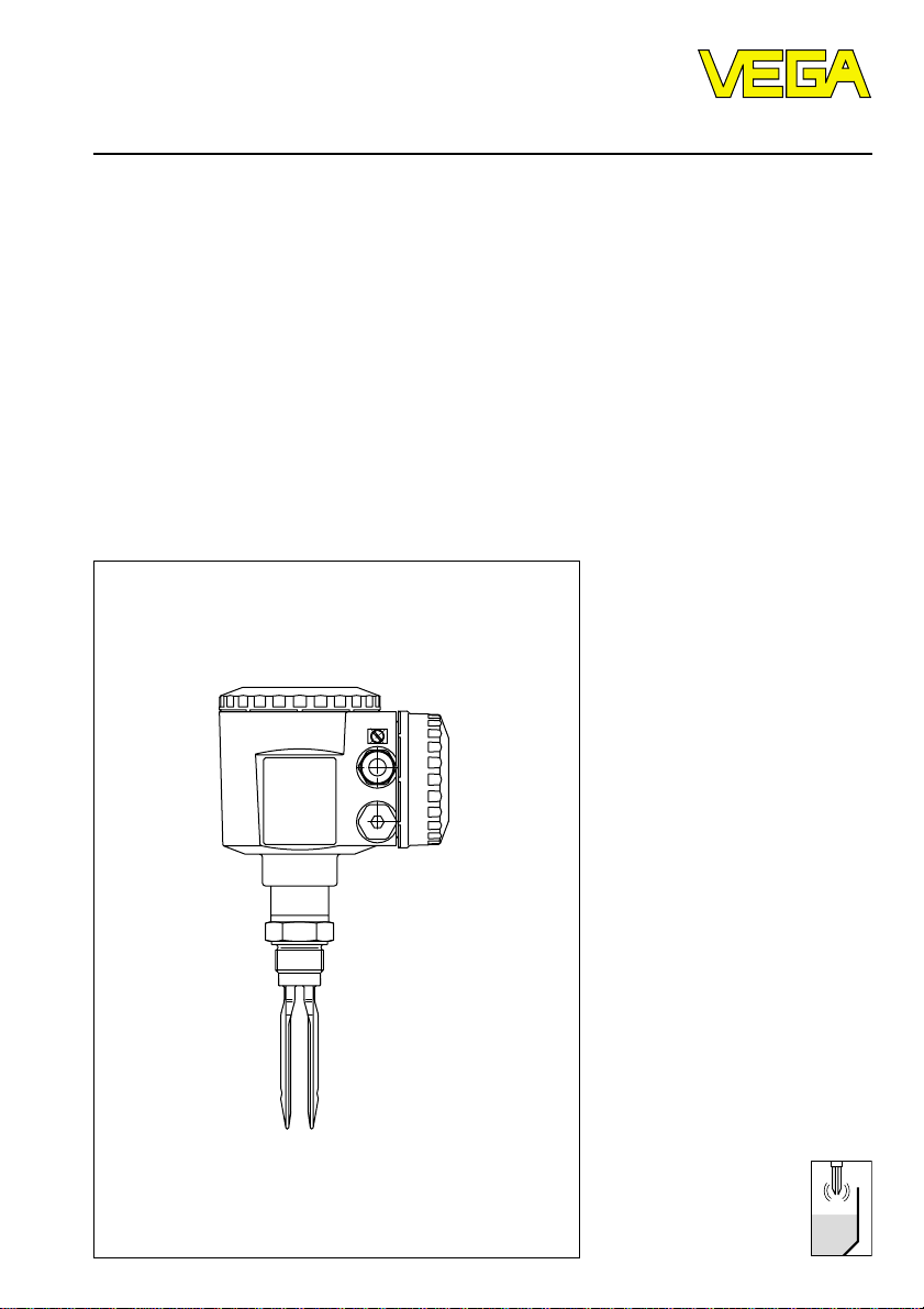
VEGASWING 81A EXD, 83A EXD
Level and Pressure
Page 2

Contents
Safety information ........................................................................ 2
Note Ex-area ................................................................................ 2
1 Product description
1.1 Function and configuration .................................................. 3
1.2 Approvals ............................................................................. 4
1.3 Technical data ....................................................................... 6
1.4 Dimensions ......................................................................... 10
1.5 Type plate ........................................................................... 14
2 Mounting
2.1 VEGASWING ...................................................................... 15
3 Electrical connection .............................................................. 18
4 Set-up
4.1 Functional table .................................................................. 23
Contents
5 Diagnosis
5.1 Recurring test acc. to WHG .............................................. 24
5.2 Exchange of electronics .................................................... 25
5.3 Failure removal ................................................................... 26
Safety information
The described module must only be installed
and operated as described in these operating
instructions. Please note that other action can
cause damage for which VEGA does not take
responsibility.
2 VEGASWING 81A EXD and 83A EXD
Note Ex-area
Please note the approval documents attached
(yellow binder), and especially the included
safety data sheet.
Page 3

Product description
1 Product description
1.1 Function and configuration
VEGASWING series 80 A vibrating level
switches detect levels of liquids with a viscosity of 0,2 mPa s up to 10.000 mPa s and a
density ³ 0,5 g/cm3. Their modular configuration allows the use in vessels, tanks and
pipelines. Typical applications ar e overfill and
dry run protections.
Due to the simple and rugged measuring
system, VEGASWING can be used virtually
in any liquid independent of the chemical and
physical characteristics. It works also under
arduous conditions such as turbulences, air
bubbles, foam generation or varying measured product and is insensitive to external
vibrations.
With the mechanical connection thread,
conus, bolting and flange, the versions are
also suitable for level detection of liquids in
the food pr ocessing industr y. For these applications the tuning fork and the extension
tube are polished.
For the use in very aggressive products,
Hastelloy C4 and coatings ECTFE (Halar)
and enamel are used for VEGASWING 81 A
and 83 A.
VEGASWING 83A with flange can be coated
with enamel up to 1200 mm and ECTFE (Halar) up to 1,6 m tube length.
For product temperatures of more than
100°C up to 150°C, VEGASWING 81 A and
83 A can be equipped with a temperature
adapter.
Function
The tuning fork is piezoelectrically energised
and vibrates at a resonance frequency of
approx. 400 Hz. If the tuning fork is covered
by the product, the resonance frequency
changes. This frequency change is detected
by the integral oscillator and converted into a
switching command. With a mode switch the
switching condition can be determined (over fill or dry run protection).
The oscillator of VEGASWING monitors continuously the instrument. The following criteria
are checked:
- corrosion or damage of the tuning fork
- vibration failure
- line break to the piezo actuation
- too low vibrating frequency
- corrosive medium penetrated into the sensor from the vessel side.
With a connected signal conditioning instrument (oscillator SWING E82 Z) in addition
more functions can be monitored. With oscillator SWING E82 Z and appropriate signal
conditioning instrument, the function of the
complete measuring chain can be monitored
by key pressing. This is valid according to
the general type approval acc. to WHG as
recurring test. More information with the appropriate signal conditioning instrument.
If one of the stated failures is determined or in
case of voltage loss, the electronics takes a
defined switching condition, i.e. dependent
on the electronics version
- the non-contact switch opens
- the relay deenergizes
- the output transistor blocks.
- a fault signal is triggered.
With the two-wire output version, the failure is
signalled via a defined current to the connected VEGATOR signal conditioning instrument.
VEGASWING 81A EXD and 83A EXD 3
Page 4
Product description
Recurring test acc. to WHG
According to the type approval to WHG
(Z-65.11-154) the recurring test acc. to WHG
can be carried out by pushing the test key
on the VEGA TOR 536 EX, 537 EX, 636 EX
signal conditioning instrument. The sensor
must neither be removed, nor should respond by filling of the vessel. This is valid for
VEGASWING 81A EXD and 83A EXD with
two-wire oscillator SWING E82 Z (EX).
VEGASWING 81A EXD and 83A EXD meet in
mode A (overfill protection) the fail-safe requirements to class 3 to class 3 (AK 1 … 3)
acc. to DIN 19 251.
Configuration
A measuring system consists of:
- a VEGASWING with oscillator
SWING E82 C, SWING E82 R or
SWING E82 T
- external instruments, switched by VEGASWING
or
- a VEGASWING with oscillator
SWING E82 Z(EX)
- VEGATOR 536 EX, 537 EX or 636 EX signal
conditioning instrument or to an already
mounted instrument, e.g. VEGA TOR
425 EX, 534 EX, 825 EX
- external instruments switched by VEGATOR.
Housing
Pressure-tight encapsulation (d)
DIN EN 50 018/VDE 0170/0171 part 5.
With a pressure-tight encapsulation the parts
which can ignite an explosive atmosphere
are located in a housing, withstanding the
pressure caused by an explosion of an explosive mixture inside and avoiding that the
explosion is spread to the explosive atmosphere around the housing.
VEGASWING with EXD-housing has a pressure-tight encapsulated space for the oscillator as well as a pressure-tight encapsulated
separate terminal box. The oscillator box is
connected via a climatically tight cable entry
with the separate terminal box. The lines for
the supply voltage and switching signals
lead via a pressure-tight encapsulated cable
entry to the terminal box of the VEGASWINGhousing. This has the advantage, that the
wiring should not be made intrinsically safe
(ia), but in increased safety and loop with a
voltage up to 250 V to the sensor. With the
signal line it is possible to control without a
signal conditioning instrument directly a DCS
or connected signallers.
Exclusively use approved cable entries for
EExd.
1.2 Approvals
Explosion protection
In hazardous areas caused by combustible
gases, vapours or fog, only certified VEGASWING 81A EXD, 83A EXD vibrating level
switches. VEGASWING 81A EXD, 83A EXD
are suitable for the use in hazardous areas of
zone 1.
The EC-type approval issued by the approval authority is attached to the instruments
as proof for the explosion protection. When
VEGASWING 81A EXD, 83A EXD vibrating
level switches are mounted and operated in
hazardous areas, the Ex-mounting regulations should be noted. The information and
conditions of the supplied certificates (ECtype approval, conformity certificate) of
VEGASWING 81A EXD, 83A EXD have to be
noted.
4 VEGASWING 81A EXD and 83A EXD
Page 5
Product description
• The mounting of Ex-systems must be generally made by skilled staff.
• VEGASWING 81A EXD, 83A EXD with
enamelled tuning fork or plastic parts acquiring static electricity (ECTFE-coated
tuning fork) have a warning label stating
measures which should be taken to avoid
dangers due to electrostatic discharges.
The contents of the warning label should
be noted.
• The explosion protection of the used electrical equipment is only ensured when the
limit temperatures stated in the certificate
are not exceeded.
• In case of dangers due to oscillation and
vibrations, the appropriate parts of
VEGASWING 83A EXD should be secured
effectively against these dangers.
Overfill protection acc. to WHG
Level detection with fault monitoring
Instrument Oscillator Level switch Test certificate no.
VEGASWING SWING E82 Z 536 EX, applied
81A EXD, 83A EXD 537 EX,
(Z) 636 EX
Overfill protection
The information and conditions of the supplied general type approvals must be noted
when a VEGASWING is used as part of an
overfill protection for vessels storing water
endangering liquids. The general type approval should be available at the installation
place.
VEGASWING should be only used in such
liquids, against the materials of the wetted
parts of VEGASWING are sufficiently chemically resistant.
DruckbehV
In a test acc. to TRB 801 no. 45 VEGASWING
was tested on the suitability for the use in
pressurized vessels (DruckbehV). The pressure and temperature information to certified
instruments are stated under "1.3 T echnical
data“.
VEGATOR
VEGASWING SWING E82 C compact instrument applied
81A EXD and SWING E82 R
83A EXD (C, R, T) SWING E82 T
Level measuring instruments for the use in hazardous areas
Level detection with fault monitoring
Instrument Oscillator Type approval
VEGASWING SWING E82 Z applied
81A EXD, 83A EXD
(Z)
VEGASWING SWING E82 C applied
81A EXD and SWING E82 R
83A EXD (C, R, T) SWING E82 T
VEGATOR 425 (EX), 534 (EX) and 825 (EX) signal conditioning instruments can be also used.
VEGASWING 81A EXD and 83A EXD 5
certificate
Page 6

Product description
1.3 Technical data
VEGASWING 81A EXD and 83A EXD
Housing
Housing material Aluminium (plastic coated)
Protection IP 66 and IP 67 (meets both protections)
Cable entry
Terminals max. 1 x 1,5 mm2 cross-section area of
Mechanical connection
Thread G 1 A or 1“ NPT
- material 1.4571 (stst) or Hastelloy C4
Flanges DIN and ANSI from DN 32
- material 1.4571, 1.4571 with Hastelloy C4 plated
Hygienic fittings
Material 1.4571 (stst)
- conus DN 25
- bolting DN 40, DN 50
- TRI-Clamp 11/2“, 2“
- Tuchenhagen Varivent DN 50 PN 10
- hyg. connection with compression nut F40 PN 25, 14571, 14581
- hyg. connection with tension flange DN 32 PN 25, 1.4571, 1.4581
Tuning fork
Material 1.4581, Hastelloy C4, Hastelloy C4 enamelled
1
/2“ NPT EExd
conductor
DN 50 PN 40 enamelled steel
or 1.4571 ECTFE-coated
1.4581, with ECTFE coated
Extension tube (VEGASWING 83A EXD)
Material 1.4571, Hastelloy C4, Hastelloy C4 enamelled
1.4571 with ECTFE coated
Length
- 1.4571, Hastelloy C4 180 mm … 4000 mm
- Hastelloy C4 enamelled 180 mm … 1200 mm
- 1.4571, ECTFE (Halar) 180 mm … 1600 mm
Weight
Basic weight approx. 2,5 kg
Tube extension approx. 0,11 kg/m
6 VEGASWING 81A EXD and 83A EXD
Page 7
Product description
Ambient conditions
1)
Ambient temperature on housing -40°C … +70°C
Storage and transport temperature -40°C … +70°C
Product temperature -40°C … +100°C
Product temperature with temperature
adapter of 1.4571 (option) -40°C … +150°C
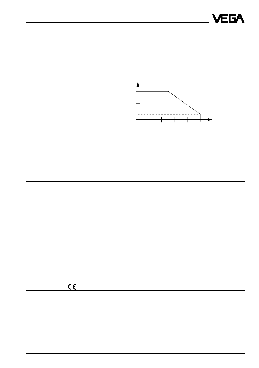
Permissible ambient temperature
'
'
'
Operating pressure
'
1)
Operating pressure -1 bar … 40 bar
(with locking ARV2EX0.C…
up to 25 bar , other locking s u npressurised)
For flange versions note nominal pressure of
the flange.
Medium
Viscosity
- dynamic 0,2 … 10.000 mPa s (or cP)
- cineatic 0,2 … 10.000 mm2/s (or cSt) relating to
density 1,0 g/cm
Density 0,5 … 2,5 g/cm
3
3
0,5 … 0,7 g/cm3 must be readjusted
(factory setting 1,0)
Product temperature with
temperature
adapter
Function
Mode A/B-mode in oscillator or definition via the signal
conditioning instrument (SWING E82 Z)
A: max. detection, overfill protection
B: min. dete ction, dry run protection
Integration time approx. 0,5 s
Meas. frequency approx. 400 Hz
Hysteresis approx. 4 mm with vertical mounting
CE-conformity
VEGASWING 81A EXD and 83A EXD vibrating level switches meet the protective regulations of EMVG (89/336/EWG) and NSR (73/23/EWG). The conformity has been judged acc.
to the following standards:
EMVG Emission EN 50 081 -1: 1992
Susceptibility EN 50 082 -2: 1995
NSR EN 61 010 -1: 1993
1)
Note the information in the conformity certificate or the EC-type approval certificate.
VEGASWING 81A EXD and 83A EXD 7
Page 8
Product description
Approvals VEGASWING 80A EXD
WHG
Approval as overfill protection acc. to WHG applied
Recurring test acc. to WHG
According to the type approval to WHG (Z-65.11-154 applied), the recurring test acc. to
WHG can be carried out by pushing the test key on the VEGA TOR 536 EX, 537 EX, 636 EX
signal conditioning instrument. The sensor must be neither removed, nor response must be
triggered by filling the vessel- This is valid for VEGASWING 81A EXD and 83A EXD with
two-wire oscillator SWING E82 Z EX.
Explosion protection VEGASWING 81A EXD, 83A EXD
Certificate EC-type approval acc. to A TEX 100 a
Classification ATEX II 2G EEx d IIC T6
Permissible application area Ex Zone 1
Ambient temperature dependent on
temperature class and Ex-Zone: see EC-type approval certificate
Electrical safety relevant
characteristics: see EC-type approval certificate
Oscillator
C - Non-contact switch (SWING E82 C)
Supply voltage 20 … 250 V AC, 50/60 Hz or 20 … 250 V DC
Output non-contact switch
Current consumption approx. 3 mA (via load circuit)
Load current min. 10 mA
Protection class I
Overvoltage category III
Modes A: max. detection, overfill protection
max. 400 mA (at I > 300 mA the ambient
temperature can be max. 60°C)
max. 4 A up to 40 ms (not WHG specified)
B: min. detection, dry run protection
8 VEGASWING 81A EXD and 83A EXD
Page 9
Product description
R - Relay output (SWING E82 R)
Supply voltage 20 … 250 V AC, 50/60 Hz or 20 … 72 V DC
(at U > 60 V DC the ambient temperature can be
max. 50°C)
Power consumption 1 … 9 VA AC, max. 1,5 W DC
Output relay output (DPDT)
2 floating spdt
Relay data
- potential separation min. 500 V DC
- contact material AgCdO and Au plated
- turn-on voltage min. 10 mV
max. 250 V AC, 250 V DC
- switching current min. 10 µA
max. 5 A AC, 1 A DC
- breaking capacitance max. 750 VA AC, 54 W DC‘
Protection class I
Overvoltage category III
Modes A: max. detection, overflow protection,
overfill protection
B: min. detection, dry run protection
T - Transistor output (SWING E82 T)
Supply voltage 10 … 55 V DC
Power consumption max. 0,5 W
Output floating transistor output
overload resistant and permanently shortcircuit
proof
Load current max. 400 mA
Voltage loss max. 1 V
Turn-on voltage max. 55 V DC
Blocking current < 10 µA
Protection class II
Overvoltage category III
Modes A: max. detection, overflow protection,
overfill protection
B: min. detection, dry run protection
Z - Two-wire output (SWING E82 Z)
Supply voltage 12 … 36 V DC (via the VEGA-signal conditioning
instrument)
Output two-wire output
Required signal conditioning instrument VEGATOR 536 EX, 537 EX, 636 EX,
VEGALOG 571
Current consumption
- tuning fork free approx. 8 mA
- tuning fork covered approx. 16 mA
- fault signal > 22 mA
Protection class II
Overvoltage category III
Modes definition via the signal conditioning instrument
VEGASWING 81A EXD and 83A EXD 9
Page 10

10 VEGASWING 81A EXD and 83A EXD
102
1.4 Dimensions
VEGASWING 81A EXD
Thread G 1 A or
1“ NPT
20
129
100
30,5
Ø 60
Ø 29
25
SW 41
116 55
25
Conus PN 25
Ø 55
Ø 80
Ø 29
159
42,5
119 30
21,5
Ø 52
Tri-Clamp 1
Ø 35,1
Ø 38,1
Ø 29
Temperature adapter of
1.4571 (option)
50
Ø 41
1
/2“
119 30
Tri-Clamp 2“
31
Ø 29
117
Bolting
DN40/50 DIN 11851
Ø 29
Switch point
1
/
Rd 65x
Ø 38
Ø 43
Rd 78x
Ø 50
Ø 55
6
Product description
1
/
6
21,5
Ø 47,8
Ø 50,8
33
35
Page 11

VEGASWING 81A EXD and 83A EXD 11
102
Product description
Compression nut
F40 PN 25
58
117
100
Rd 65x
40
Ø 79,6
159
Ø 29
Ø 52
Flange DN 50
Ø 29
120 40
42,5
Tension flange
F32 PN 25
Ø 90
Ø 72/6xM6
Ø 79,6
Ø 29
Ø 29
117 58
25
1
/
6
40
Tuchenhagen
Varivent
120 29
Temperature adapter of
1.4571 (option)
Ø 41
Flange DN 50
enamelled
40
120
50
Ø 31
Switch point
Page 12

12 VEGASWING 81A EXD and 83A EXD
102
VEGASWING 83A EXD
Thread G 1 A or
1“ NPT
20
L (min. 180, max. 4.000 mm)
100
30,5
SW 41
Ø 29
25
Ø 60
159
42,5
Conus PN 25
55
Ø 29
L (min. 180, max. 4.000 mm)
25
Ø 55
Ø 80
Ø 52
Ø 35,1
Ø 38,1
1
Ø 29
Tri-Clamp 1
30
L (min. 180, max. 4.000 mm)
21,5
Temperature adapter of
1.4571 (option)
50
Ø 41
Bolting
/2“
Tri-Clamp 2“
30
Ø 29
L (min. 180, max. 4.000 mm)
DN40/50 DIN 11851
31
Ø 29
L (min. 180, max. 4.000 mm)
Switch point
Product description
Rd 78 x 1/6
35
Ø 50
Ø 55
21,5
Ø 47,8
Ø 50,8
Rd 65 x 1/6
33
Ø 38
Ø 43
Page 13

Locking for height adjust-
ment up to 25 bar
½
½
Temperature adapter of
1.4571 (option)
Ø
Compression nut
Locking for height
adjustment
½
½
F40 PN 25
Ø
Ø
Tension flange
F32 PN 25
Ø
Ø
Ø
Ø
Tuchenhagen
Varivent
Flange DN 50
Ø
Ø
Ø
Flange DN 50
enamelled
Ø
Page 14

Product description
1.5 T ype plate
Before mounting and electrical connection,
please check if the correct instrument is
used. Note the type plate which is located as
follows:
Type plate
The type plate contains important data required for mounting and connection. The
configuration and the parts of the type plate
are explained in the following example.
Configuration of the type plate (example)
1
2
3
4
type: S81GNN.RAK
see certificate
PTB 99 ATEX XXXX
II 2G EEx d IIC T6
electronics: R
power supply: 20…250VAC.
20…60VDC
protection: IP67
Ord.no.:123456/000
Z-11.65-
0032
1999
Insp.
ser.no. XXXXXXXX
6
1 Master data of the order no.
2 Ex-certification number/Ex-classification
Explosion protected version - note the
information and conditions in the certificate
3 Data of the electronics
4 No. of the order confirmation/Pos.-no.
5 Serial number
6 Test mark when used as par t of an over fill
protection for vessels storing water endan-
gering liquids - note the information and
conditions of the general type approval
7 Manufacturing year
8 Test authority no. CE
8
7
5
Order code
Detailed information to the order code is
stated in the "Product Information Vibration “
or in the "VEGA-pricelist “.
14 VEGASWING 81A EXD and 83A EXD
Page 15

Mounting
2 Mounting
2.1 VEGASWING
Generally VEGASWING can be mounted in
any individual position. The instrument must
be mounted such that the tuning fork is at the
height of the requested switch point. Note the
following installation instructions:
Transport
Do not hold VEGASWING on the tuning fork.
Especially with flange or tube versions, the
tuning fork can be damaged by the instrument weight. T ransport enamelled and
ECTFE-coated instruments very carefully and
avoid touching the tuning fork.
Switch point
The tuning fork is provided with lateral markings (notches) marking the switch point with
vertical installation relating to the medium
water. Note when installing VEGASWING that
the marking is at the height of the requested
level. Note that the switch point of the instrument shifts when the medium has a density
deviating from water (water = 1,0 g/cm3). The
switch point can be adapted via a potentiometer, to set the switch point to the marking
(notch). With the adjustment 1,0 g/cm3 a
switch point from a density of ³ 0,7 g/cm3 is
ensured. For products with a density < 0,7 g/
cm3 the potentiometer must be readjusted on
the oscillator. Oscillator SWING E82 Z:
0,5 … 1,0 g/cm3 (see fig. 2.1). The switch
point adaption is described under "4 Set-up “.
Vertical installation
from top, from bottom
Switch point with
low density
Switch
point
approx.
25 mm
Switch point at
higher density
Switch
point
75 mm
Fig. 2.1
Horizontal installation
Switch point
Recommended installation position for adhesive products:
Top marking
Switch
point
approx.
15 mm
Fig. 2.2
Adhesive products
In case of horizontal mounting in adhesive
and viscous products, the surfaces of the
tuning fork should be vertical to reduce buildup on the tuning fork (see fig. 2.2). The position of the tuning fork is marked by a notch
on the hexagon of VEGASWING. Therefore
you can check the position of the tuning fork
when screwing in. When the hexagon is on
the seal, the thread can be still turned by
approx. half a turn. This is sufficient to reach
the recommended installation position.
VEGASWING 81A EXD and 83A EXD 15
Page 16

Mounting
n case of adhesive and viscous products,
the tuning fork should protrude into the vessel to avoid build-up. Sockets for flanges and
mounting bosses should not exceed a cer tain length. For flange versions, the socket
should have a length of max. 40 mm, for
threads max. 30 mm, see also Welded
socket.
Pressure
In case of gauge or low pressure in the vessel, the mounting boss must be sealed on the
thread. Cover the thr ead with Teflon tape,
hemp or similar or use a sufficiently resistant
seal ring.
Vibrations
Extreme vibrations and shocks, e.g. by stir rers and turbulences in the vessel, can
cause the extension tube of VEGASWING
83A EXD to resonance vibrations. This
causes an increased wear on the upper weld
joint.
Provide an appropriate fixing or fastening
directly above the tuning fork to fasten the
extension tube (see fig. 2.3).
Stirrers
Due to stirrers or similar the level switch can
be subjected to strong lateral forces. Due to
this do not choose a too long extension tube
of VEGASWING 83A EXD but check if it is not
possible to mount a VEGASWING 81A EXD
level switch laterally in horizontal position.
EExd-cable entries
Use cable with a round cross-section area of
conductor and tighten the cable entr y. The
EExd-cable entry is suitable for cable diameters of 3,1 mm to 8,7 mm.
The careful sealing of the cable entry is very
important when mounting outside, in humid
areas (e.g. by cleaning processes) or on
cooled or heated vessels (see fig. 2.4).
VEGASWING with relay oscillator SWING
E82R can be equipped with a second EExdcable entry. This is attached to the instrument. Exclusively use for EExd approved
cable entries.
• Loosen the blind stopper and remove it.
• Screw the cable entry into the housing and
tighten the cable entr y.
This is mainly valid for applications in
Ex-area category 2G or WHG. Note
that the tube will not be bent by this
measure.
Fig. 2.3
16 VEGASWING 81A EXD and 83A EXD
Humidity
Turn the cable entr y of horizontally mounted
instruments to the bottom, to avoid humidity
ingress. The plastic housing can therefore be
rotated by approx. 330 °. On vertically installed instruments loop the connection line to
the instrument housing to the bottom, so that
rain or condensation water can drain off. This
is mainly valid for mounting outside, in humid
areas (e.g. by cleaning processes) or on
cooled or heated vessels (see fig. 2.4).
Page 17

Mounting
Fig. 2.4
Lockings
For VEGASWING 83A EXD with screw connection, a locking is available for height adjustment. With this locking it is possible to
adjust and modify the switch point after installation.
Bring the switch point of the tuning fork to the
requested height. By tightening the pressure
screw, you lock the tube in this position.
Secure the pressure screw with the fixing
screw against loosening.
You can use VEGASWING 83A EXD in vessels with up to 25 bar pressure. Use the
locking (G 11/2 A, 11/2“ NPT) up to 25 bar
(ARV2EX0.C…). Note the operating instructions of the locking.
Fig. 2.5
VEGASWING with enamel or ECTFE
Treat instruments with enamel or ECTFEcoating very carefully and avoid shocks.
Unpack VEGASWING just before mounting.
Insert VEGASWING carefully into the provided vessel opening and avoid contact with
sharp-edged vessel parts.
Flow
(e.g. in tubes)
When mounting in tubes or in vessels with
certain flow direction, you should mount
VEGASWING such that the surfaces of the
tuning fork are along with the flow direction,
see also Welded socket .
Lateral load
Note that the vibrating element is not subjected to lateral forces. Mount the instrument
on a position in the vessels wher e no interfering influences such as e.g. by stirrers, filling
openings etc. can occur . This is mainly due
for instrument types with cable or extension
tube (see fig. 2.5). The surfaces of the tuning
fork should be in parallel to the product
movement, so that the tuning fork of VEGASWING only offers little resistance.
VEGASWING 81A EXD and 83A EXD 17
Page 18

Mounting, electrical connection
Welded socket
VEGASWING has a defined begin of the
thread. This means that each VEGASWING is
in the same position after screwing in. Therefore remove the supplied seal from the
thread of VEGASWING. This seal is not required when using a welded socket. Screw
VEGASWING into the welded socket.
You can determine the later position of
VEGASWING already before welding (see
fig. 2.2). Mark the appropriate position of the
welded socket. Before welding you have to
unscrew VEGASWING and remove the rubber ring out of the welded socket.
Optionally a welded socket is available which
is already provided with a marking. Weld this
welded socket with the marking to the top
(see fig. 2.6).
Marking
Fig. 2.6
Installation examples
3 Electrical connection
Danger
Switch off the power supply before starting
connection work.
The electrical connection must be carried out
dependent on the integral oscillator . Connect
mains voltage according to the following
connection diagrams. Note the following
special instructions for electrical connection in
Ex-areas.
Electronics box (large cover)
Connection box
(small cover)
Fig. 2.8
When connecting the voltage supply or reconnecting the sensor , the instrument passes
the function test (only with oscillator
SWING E82Z and connected signal conditioning instrument). See also "5.1 Recurring
test acc. to WHG “.
Note
If strong electromagnetic interferences have
to be expected, we recommend to use
screened cable for the Z-electronics. The
screening of the cable must be earthed on
the sensor side (VEGASWING) via the inter nal earth terminal.
Generally connect VEGASWING with P A. Use
the earth connection terminal on the housing.
Mounting not
suitable for
adhesive products
• Interrupt all lines to the sensor (voltage
supply and signal lines) on the switching
cabinet.
Fig. 2.7
18 VEGASWING 81A EXD and 83A EXD
Page 19

“ “
Non-contact switch (SWING E82 C)
•
•
•
•
–
–
…
…
•
•
•
•
Page 20

Floating relay output (SWING E82 R)
… …
Floating transistor output
(SWING E82 T)
T wo-wire output (SWING E82 Z)
…
…
Page 21

Connection examples
Control of alternating current loads
…
Note
Page 22

4 Set-up
Indicating and adjustment elements
“
“
Switch point adaption
Fault monitoring
“
Page 23

4.1 Functional table
Mode A
Mode B
Failure of
the voltage
supply(mode
A/B)
Level Switching condition Control Current Control Control
SWING SWING SWING lamp consump. lamp lamp
E82 C
1)
E82 R
1)
E82 T VEGA- SWING VEGA- VEGA-
SWING E82 Z SWING TOR
Failure
Note:
Page 24

5 Diagnosis
Diagnosis
5.1 Recurring test acc. to WHG
The implementation of the recurring test acc.
to WHG is stated in the general type approval no. Z-65.11-154 (see paragraph 8 of
the certificate).
Note these approvals when VEGASWING
81A EXD and 83A EXD are used as part of
an overfill protection acc. to WHG.
VEGASWING 81A EXD and 83A EXD with
VEGATOR 536 EX, 537 EX, 636 EX signal
conditioning instruments meet in mode A
(overfill protection) the requirements acc. to
AK 3.
Recurring test acc. to WHG
According to the type approval to WHG (no.
Z-65.11-154) the recurring test acc. to WHG
can be carried out by pushing the test key
on the VEGA TOR 536 EX, 537 EX, 636 EX
signal conditioning instrument. The sensor
must neither be removed, nor a filling of the
vessel is necessary for responding of the
sensor. This is valid for VEGASWING
81A EXD and 83A EXD with two-wire oscillator SWING E82 Z EX.
With the provided current values you can
carry out the function test also directly via a
DCS or a processing system.
The implementation and the switching sequence of the function test are stated under
"Test key“ and the following table in the oper ating instructions of the appropriate VEGATOR signal conditioning instrument.
Test key
For coordinations in conjunction with two-wire
oscillator (SWING E82Z EX) a function test
can be carried out. The VEGA TOR signal
conditioning instrument has an integral test
key. The test key is lower ed in the fr ont plate
of the signal conditioning instrument. Push
the test key with a suitable object (screwdriver, pen etc.). When pushing the key , the
system is checked on the following criteria:
- switching function of the switching outputs
- switching function of the failure outputs
- potential separation of the outputs
- signal processing of the signal conditioning
instrument.
After pushing the test key , the complete
measuring system will be checked on correct
function. During the test the following operating conditions are simulated:
- fault signal
- empty signal
- full signal.
Check if all three switching conditions occur
in the correct sequence and the stated duration. If this is not the case, there is a failure in
the measuring system (see "5.2 Failure removal“ in the operating instructions of the
signal conditioning instrument). Note that the
connected instruments are activated during
the function test. Hence you can check the
correct function of the measuring system.
Due to this fault monitoring, the combination
of the following instruments corresponds to
classes 1 to 3 (AK 3) acc. to DIN 19 251.
AK 3 means that the system is fail safe.
- VEGASWING 81A EXD, 83A EXD
- oscillator SWING E82Z EX
- VEGATOR 536 EX, 537 EX and 636 EX
signal conditioning instrument
24 VEGASWING 81A EXD and 83A EXD
Page 25

Diagnosis
Test course A-mode B-mode
1 Simulation of a fault signal (after release of key approx. 3 s)
Level relay deenergized > 22 mA
Failure relay deenergized < 2,2 mA
1)
2)
2)
2 Simulation of an empty signal (approx. 1,5 s)
Level relay energized 8 mA
2)
Failure relay energized
3 Simulation of a full signal (approx. 1,5 s)
Level relay deenergized 16 mA
2)
Failure relay energized
4 Return to the actual operating condition (covered/uncovered)
1)
as long as the key is pushed, the instrument signals failure.
2)
condition of VEGASWING
With the provided current values, you can also carry out the function test directly via a DCS or
a processing system
5.2 Exchange of electronics
• Fasten the housing cover and remove the
screw on the electronics box. Note that the
• Interrupt the voltage supply and disconnect the connection lines and the switching
current circuit on the switching cabinet.
• Make sure that there is no Ex-atmosphere.
screw head is turned in one of the openings.
• Switch on the power supply . The sensor is
immediately ready for operation.
• Loosen the four screws of the housing
cover with a screwdriver and remove the
cover.
• Disconnect the connection lines on the
oscillator.
• Remove the old oscillator and insert the
new one.
• Set the A/B-switch to the same position as
on the old oscillator (not with SWING
E82 Z).
• Set the potentiometer for the density adjustment of the new electronics to the same
value as on the old oscillator.
• Connect the connection lines again.
VEGASWING 81A EXD and 83A EXD 25
Page 26

5.3 Failure removal
Failure Measure, failure removal
…
W
Page 27

Diagnosis
b.Current value > 22 mA
- Check all connections and the connection line to the sensor .
- Should the red failure lamp still light, separate the sensor from the
connection line and connect instead a r esistor of 1 kW.
When the failure lamp extinguishes, the sensor will be defect. Check
the connected sensor.
- Should the failure lamp still light, connect the sensor again. Separate
the signal conditioning instrument from the connection line and connect to the sensor input a r esistor of 1 kW.
- Should the failure lamp still light, the signal conditioning instrument will
be defect. In this case return the instrument for repair to VEGA.
- When the failure lamp extinguishes, there is probably a shortcircuit in
the connection line. Check the connection line to the sensor .
Malfunction during After pushing the test key , the switching conditions do not occur in the
function test correct sequence or the correct period, e.g. there is no full signal
provided.
- Measure the line resistance
When the line is high-resistance, you have to take appropriate measures to reach a standard resistance. E.g. check the terminals and
cable connections on corrosion.
VEGASWING 81A EXD and 83A EXD 27
Page 28

VEGA Grieshaber KG
Am Hohenstein 113
D-77761 Schiltach
Phone (0 78 36) 50 - 0
Fax (0 78 36) 50 - 201
e-mail: info@vega-g.de
ISO 9001
The statements on types, application, use and operating conditions
of the sensors and processing systems correspond to the actual
knowledge at the date of printing.
Technical data subject to alteration.
2.23 631 / July ’99
 Loading...