

Page 1
Operating Instructions
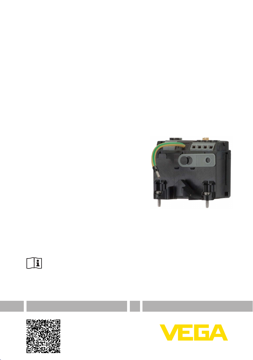
Supplementary electronics
Overvoltage protection
Document ID: 46670
Page 2

Contents
Contents
1 About this document
1.1 Function ........................................................................................................................... 3
1.2 Target group ..................................................................................................................... 3
1.3 Symbolism used ............................................................................................................... 3
2 For your safety
2.1 Authorised personnel ....................................................................................................... 4
2.2 Appropriate use ................................................................................................................ 4
2.3 Approvals ......................................................................................................................... 4
2.4 Environmental instructions ............................................................................................... 4
3 Product description
3.1 Conguration .................................................................................................................... 5
3.2 Principle of operation........................................................................................................ 5
3.3 Packaging, transport and storage ..................................................................................... 5
4 Mount and connect
4.1 Mounting steps ................................................................................................................. 7
4.2 Connecting ....................................................................................................................... 8
5 Maintenance
5.1 How to proceed if a repair is needed ................................................................................ 9
6 Dismounting
6.1 Disposal ......................................................................................................................... 10
7 Supplement
7.1 Technical data ................................................................................................................ 11
46670-EN-140108
Editing status: 2014-01-07
2
Supplementary electronics • Overvoltage protection
Page 3
1 About this document
1 About this document
1.1 Function
This operating instructions manual provides all the information you
need for mounting, connection and setup as well as important instructionsformaintenanceandfaultrectication.Pleasereadthisinformation before putting the instrument into operation and keep this manual
accessible in the immediate vicinity of the device.
1.2 Target group
This operating instructions manual is directed to trained specialist
personnel. The contents of this manual should be made available to
these personnel and put into practice by them.
1.3 Symbolism used
Information, tip, note
This symbol indicates helpful additional information.
Caution: If this warning is ignored, faults or malfunctions can result.
Warning: If this warning is ignored, injury to persons and/or serious
damage to the instrument can result.
Danger: If this warning is ignored, serious injury to persons and/or
destruction of the instrument can result.
Ex applications
This symbol indicates special instructions for Ex applications.
List
•
The dot set in front indicates a list with no implied sequence.
Action
→
This arrow indicates a single action.
1 Sequence of actions
Numbers set in front indicate successive steps in a procedure.
Battery disposal
This symbol indicates special information about the disposal of batteries and accumulators.
46670-EN-140108
Supplementary electronics • Overvoltage protection
3
Page 4

2 For your safety
2 For your safety
2.1 Authorised personnel
All operations described in this operating instructions manual must
be carried out only by trained specialist personnel authorised by the
plant operator.
During work on and with the device the required personal protective
equipment must always be worn.
2.2 Appropriate use
The electronics modules, accumulators, emitting electronics, housings or process components described in this manual are replacement parts for existing sensors.
2.3 Approvals
Depending on the version, instruments with approvals can have
deviating technical data. For these instruments, the corresponding
approval documents must be observed. These documents are part of
the scope of delivery or can be downloaded from www.vega.com via
"VEGA Tools" and "serial number search" as well as via "Downloads"
and "Approvals".
2.4 Environmental instructions
Protection of the environment is one of our most important duties.
That is why we have introduced an environment management system
with the goal of continuously improving company environmental pro-
tection.Theenvironmentmanagementsystemiscertiedaccording
to DIN EN ISO 14001.
Pleasehelpusfulllthisobligationbyobservingtheenvironmental
instructions in this manual:
Chapter "Packaging, transport and storage"
•
Chapter "Disposal"
•
46670-EN-140108
4
Supplementary electronics • Overvoltage protection
Page 5

Scope of delivery
Area of application
3 Product description
3 Product description
3.1 Conguration
The scope of delivery encompasses:
Supplementary electronics overvoltage protection
•
Documentation
•
– this operating instructions manual
– ifnecessary,furthercerticates
3.2 Principle of operation
The supplementary electronics overvoltage protection is a replacement component for sensors with overvoltage protection:
VEGAPULS series 60
•
– Hardware version from 2.0.0
– Software version from 4.0.0
VEGAFLEX 80 series
•
VEGABAR series 80
•
Functional principle
The supplementary electronics 4 … 20 mA/HART - four-wire is used
for connection of the sensor to mains voltage 9.6 … 48 V DC or
20 … 42 V AC or 90 … 253 V AC
3.3 Packaging, transport and storage
Packaging
Transport
Transport inspection
Storage
46670-EN-140108
Supplementary electronics • Overvoltage protection
Your instrument was protected by packaging during transport. Its
capacity to handle normal loads during transport is assured by a test
based on ISO 4180.
The packaging of standard instruments consists of environmentfriendly, recyclable cardboard. For special versions, PE foam or PE
foil is also used. Dispose of the packaging material via specialised
recycling companies.
Transport must be carried out in due consideration of the notes on the
transport packaging. Nonobservance of these instructions can cause
damage to the device.
The delivery must be checked for completeness and possible transit
damage immediately at receipt. Ascertained transit damage or concealed defects must be appropriately dealt with.
Up to the time of installation, the packages must be left closed and
stored according to the orientation and storage markings on the
outside.
Unless otherwise indicated, the packages must be stored only under
the following conditions:
Not in the open
•
Dry and dust free
•
Not exposed to corrosive media
•
Protected against solar radiation
•
Avoiding mechanical shock and vibration
•
5
Page 6

3 Product description
Storage and transport
temperature
Storage and transport temperature see chapter "Supplement -
•
Technical data - Ambient conditions"
Relative humidity 20 … 85 %
•
46670-EN-140108
6
Supplementary electronics • Overvoltage protection
Page 7

Mounting steps
4 Mount and connect
4 Mount and connect
4.1 Mounting steps
The supplementary electronics is mounted in the power supply compartment. The following illustration shows the position of the power
supply compartment in the double chamber housing.
1
Fig. 1: Position of the power supply and electronics compartment
1 Supply room (supplementary electronics)
2 Electronics compartment (sensor electronics)
2
Proceed as follows:
1. Unscrew housing cover of the power supply compartment
2. Loosen the two holding screws of the supplementary electronics
with a screwdriver (Torx size T 10 or slot size 4)
1
Surge
Protection
Display
2
+
( )
(-)
1
2
5
678
Fig. 2: Power supply compartment with supplementary electronics
1 Supplementary electronics
2 Screws (2 pcs.)
3. Pull the previous supplementary electronics out by using the
dismounting tool.
4. Insert the new supplementary electronics module carefully.
5. Screw in the two holding screws and tighten them
6. Screw the housing cover back on
The supplementary electronics is exchanged.
As a rule, the exchange of the supplementary electronics must be
documented internally when used in Ex applications.
46670-EN-140108
Supplementary electronics • Overvoltage protection
7
Page 8

4 Mount and connect
2
Connection compartment
- overvoltage arrester
4.2 Connecting
Note:
The connection is carried out according to chapter "Connecting to
voltage supply" of the operating instructions manual of the respective
sensor.
Surge
Protection
( )
+
(-)
1
2
5
Display
678
3
4
1
Fig. 3: Terminal compartment, double chamber housing
1 Voltage supply/Signal output
2 For display and adjustment module or interface adapter
3 Connection of the overvoltage protection to the ground terminal
4 Ground terminal for connection of the cable screen or for low impedance
connection to the potential equalization cable
1)
46670-EN-140108
1)
8
Supplementary electronics • Overvoltage protection
Page 9

5 Maintenance
5 Maintenance
5.1 How to proceed if a repair is needed
Youcanndarepairformaswellasdetailedinformationonhowto
proceed under www.vega.com/downloads and "Forms and certi-
cates".
By doing this you help us carry out the repair quickly and without having to call back for needed information.
If a repair is necessary, please proceed as follows:
Printandlloutoneformperinstrument
•
Clean the instrument and pack it damage-proof
•
Attach the completed form and, if need be, also a safety data
•
sheet outside on the packaging
Please contact the agency serving you to get the address for
•
thereturnshipment.Youcanndtheagencyonourhomepage
www.vega.com.
46670-EN-140108
Supplementary electronics • Overvoltage protection
9
Page 10

6 Dismounting
6 Dismounting
6.1 Disposal
The instrument consists of materials which can be recycled by specialised recycling companies. We use recyclable materials and have
designed the parts to be easily separable.
Correctdisposalavoidsnegativeeectsonhumansandtheenvironment and ensures recycling of useful raw materials.
Materials: see chapter "Technical data"
If you have no way to dispose of the old instrument properly, please
contact us concerning return and disposal.
WEEE directive 2002/96/EG
This instrument is not subject to the WEEE directive 2002/96/EG and
the respective national laws. Pass the instrument directly on to a specialised recycling company and do not use the municipal collecting
points. These may be used only for privately used products according
to the WEEE directive.
10
46670-EN-140108
Supplementary electronics • Overvoltage protection
Page 11

7 Supplement
7 Supplement
7.1 Technical data
Technical data
The technical data are listed in the operating instructions manual of the respective sensor.
46670-EN-140108
Supplementary electronics • Overvoltage protection
11
Page 12

Printing date:
All statements concerning scope of delivery, application, practical use and operating conditions of the sensors and processing systems correspond to the information
available at the time of printing.
Subject to change without prior notice
© VEGA Grieshaber KG, Schiltach/Germany 2014
VEGA Grieshaber KG
Am Hohenstein 113
77761 Schiltach
Germany
Phone +49 7836 50-0
Fax +49 7836 50-201
E-mail: info.de@vega.com
www.vega.com
46670-EN-140108
 Loading...