

Page 1

Model IP25300
IP223 – EF Johnson RS5300
Interface
Technical Manual
April 2007 LIT000015000
Revision B
Page 2

Page 3

TABLE OF CONTENTS
1 GENERAL................................................................................................................. 2
2 FRONT AND REAR PANEL CONNECTIONS ................................................... 2
2.1 F
2.2 R
RONT PANEL LEDS............................................................................................ 2
EAR PANEL CONNECTOR ................................................................................... 3
3 IP223 AND EF JOHNSON RS5300 SETUP .......................................................... 3
3.1 IP223 SETUP........................................................................................................ 3
3.1.1 Jumper Settings........................................................................................... 3
3.1.2 Web Page Setup .......................................................................................... 3
3.2 EQUIPMENT CONNECTION.................................................................................... 4
3.3 EF JOHNSON RS5300 RADIO SETUP .................................................................... 5
3.4 C-SOFT SETUP ..................................................................................................... 8
3.4.1 Setup IP Multicast List................................................................................ 8
3.4.2 C-Soft Control Buttons................................................................................ 8
4 SYSTEM START UP ............................................................................................... 9
5 AUDIO ALIGNMENT............................................................................................. 9
5.1 RECEIVE AUDIO ALIGNMENT............................................................................... 9
5.2 TRANSMIT AUDIO ALIGNMENT.......................................................................... 10
6 IP25300 ASSEMBLIES.......................................................................................... 11
7 WARRANTY, SERVICE, REPAIR, AND COMMENTS.................................. 12
List of Figures
Figure 1 Multicast Setup Screen IP-223 Showing Local Mode Setup ............................... 2
Figure 2 IP25300 Setup Page.............................................................................................. 4
Figure 3 IP25300 Interface Cable....................................................................................... 4
Figure 4 IP25300 Cable Connectors................................................................................... 5
Figure 5 EF Johnson RS5300 Radio Button Locations...................................................... 7
Figure 6 C-Soft Multicast Line Setup................................................................................. 8
Figure 7 C-Soft Control Setup............................................................................................ 8
Figure 8 IP223 Receive Alignment..................................................................................... 9
Figure 9 IP223 Transmit Alignment................................................................................. 10
Page 4
2 IP25300 Radio Interface
1 General
The IP25300 Radio Interface is designed to connect
the IP-223 Ethernet Adapter Panel to an EF Johnson
RS5300 mobile radio. The IP223 provides radio
control for Zone/Channel change, Monitor, Scan, and
Clear/Secure operation. The radio PTT ID and
EMERGENCY PTT ID for incoming calls are
decoded and displayed on the console.
Note, IP25300 radio control is only available in C-Soft/IP-223 Software Versions
3.000 and higher.
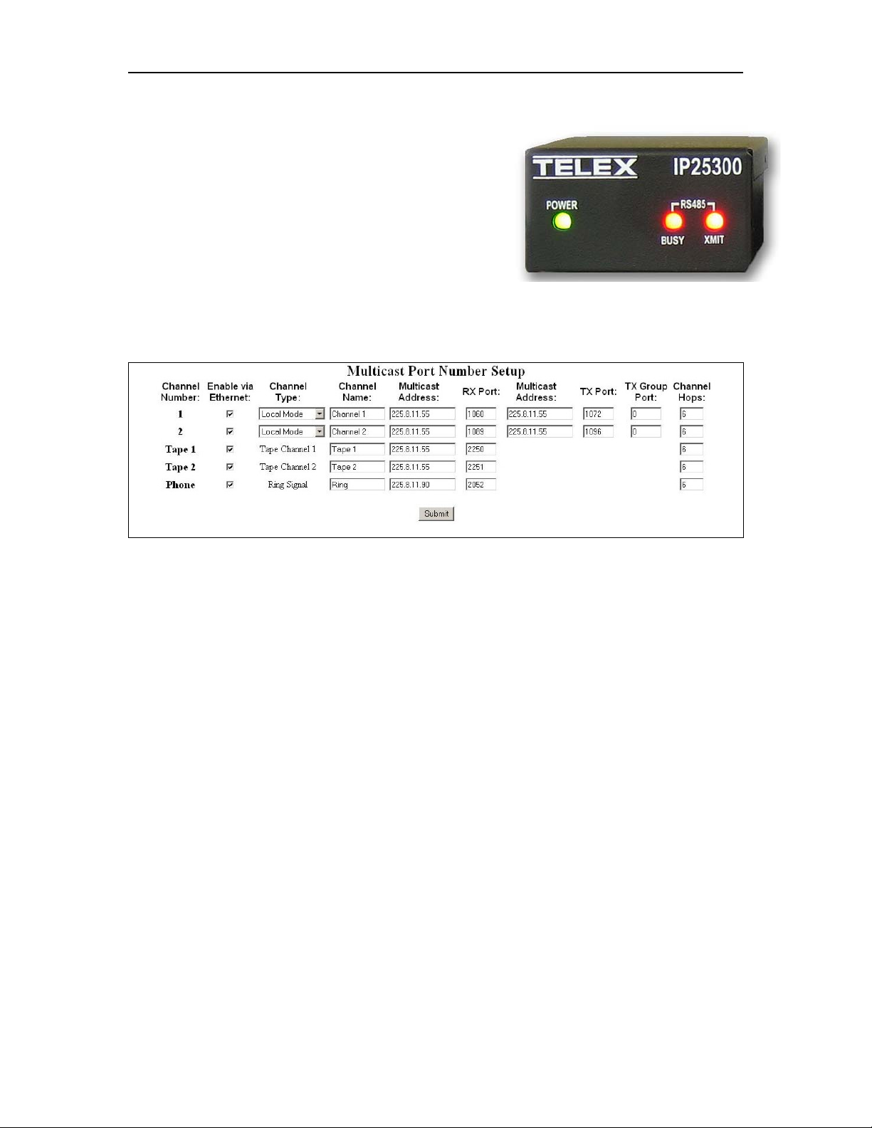
Figure 1 Multicast Setup Screen IP-223 Showing Local Mode Setup
The IP-223 initially must be configured for the Local Mode to control the IP25300. Local
Mode is selected from the Multicast Setup Screen of the IP-223. See Figure 1
Each line has a pull down menu that allows selection of the Local Mode. The multicast
address and port numbers are configured just as any other mode. Zone/Channel and
RS485 address data is entered at the Per Line Setup screen. Figure 2 shows a typical
screen with EF Johnson information.
For C-Soft or console configurations, please refer to the specific User Manual for that
product.
2 Front and Rear Panel Connections
2.1 Front Panel LEDs
Power: Green LED indicates power to the IP25300
RS485 BUSY: Red LED indicates activity on the radio RS485 bus
RS485 XMIT: Red LED indicates the IP223 is sending data to the radio
Page 5

IP25300 Radio Interface 3
2.2 Rear Panel Connector
There is only a single connector on the rear of the IP25300. All connections terminate on
the DB25.
Pin # Signal Pin # Signal
1) +12VDC 14) RS485 B
2) IP223 Transmit Data 15) PTT
3) IP223 Receive Data 16) RS485 Busy
4) RS485 A 17) Radio Ground
5) GROUND 18) EFJ Mic Audio
6) EFJ Mic Audio 19) EFJ Speaker Audio
7) EFJ Speaker Audio 20) NC
8) PTT 21) PTT Common
9) DIGI2 RS485 Busy 22) N/C
10) NC 23) DIGI3 RS485 XMIT
11) GROUND 24) IP223 RX+
12) IP223 RX- 25) IP223 TX+
13) IP223 TX- Shield Ground
3 IP223 and EF Johnson RS5300 Setup
3.1 IP223 Setup
3.1.1 Jumper Settings
Jumper position Connection Type:
“B” Balanced 600 Ohm
Line 1: J3, J9, J11, J16, J21
Line 2: J25, J28, J29, J19, J20
“A” 600 Ohm Rx Termination
Line 1: J14
Line 2: J24
Serial Port Communications Jumpers: Local mode – EFJ5300
Line 1: J35 “A”
Line 2: J26 “A”
3.1.2 Web Page Setup
Figure 1 shows the Multicast Setup page. This is the location that The IP25300 is initially
configured via the pull down menu for Channel Type. It must be done first to allow the
appropriate information on the Per Line Setup page to be entered. The “Serial Port
Mode” information must be the first entry on the Per Line Setup page. Select “ EF
Johnson 5300” from the pull down menu then press “Submit”, this will set the page for
EF Johnson data.
Page 6

4 IP25300 Radio Interface
The RS485 address and all of the Zone/Channels is the required radio information. Select
the “RS485 Address” the choices are 2 – 7. The default is 2 and will be acceptable for
most installations. Enter the radio’s Zone and Channel numbers in the right hand boxes.
The maximum Zone number is 32 and the maximum Channel number 16. If numbers
greater than these are entered, the data will default back to Zone 1 – Channel 1 when
“Submit” is pressed.
Figure 2 IP25300 Setup Page
3.2 Equipment Connection
The IP223, IP25300, and the EF Johnson RS5300 radio are connected using the cable
provided with the IP25300 assembly. See Figure 3
Figure 3 IP25300 Interface Cable
Figure 4 shows each connector labeled with the connection destination (i.e. To IP223,
EFJ5300, etc.) One or both radio ports on the IP-223 may be used. If both ports are used,
a DB9 splitter cable is required to route serial channel one and two to the respective
IP25300. This can be purchased from the factory. Part number: 301953000
Page 7

IP25300 Radio Interface 5
Figure 4 IP25300 Cable Connectors
3.3 EF Johnson RS5300 Radio Setup
To operate with the IP223, the only radio hardware requirement is the 25-pin option
connector (EF Johnson P/N 5972002245) connected internally to J6 and J8 on the PPC
logic board.
Note; When the cable is delivered with the radio its connections within the radio
needs to be moved, follow the step by step instructions to accomplish.
Steps 1 - Open bottom radio access panel, locate cable assy.
P/N 5972002245 as
Accessory Pigtail as
Page 8

6 IP25300 Radio Interface
Step 2 – Lift out cable 5972002245 from pass-thru channel, relocate Accessory Pigtail
cable.
Accessory Pigtail new
Step 3 – Disconnect cable assembly from this header and cut black ground lug wire.
Cut wire, leave lug in
Disconnect
Page 9

IP25300 Radio Interface 7
Step 4 – Press cable 5972002245 into open pass-thru channel, connect cable assembly
into new header location, replace panel cover.
P/N 5972002245
Note: The radio should have firmware version 4.4.21 or higher installed.
The operating parameters for the EF Johnson RS5300 radio are programmed from the
PCConfigure® application provide by EF Johnson.
Note: PCConfigure® version 1.28 or higher should be used
In addition to the channel type, talk groups and frequencies dictated by the specific
installation, radio buttons F4, F5 and F6 MUST be specifically programmed for control
by C-Soft. Figure 5 Shows the location of each control button on the RS5300 radio.
Monitor
Scan
Clear/Secure
Figure 5 EF Johnson RS5300 Radio Button Locations
Program the radio buttons as follows:
F4 = CLEAR/SECURE
F5 = SCAN ON/OFF
F6 = MONITOR
Page 10

8 IP25300 Radio Interface
The IP223 will decode and send the incoming PTT ID and EMERGENCY PTT ID to the
console. The radio must be programmed to display the PTT ID upon receipt of the call.
Set the display time of the PTT ID and EMERGENCY PTT ID to “Inf”
3.4 C-Soft Setup
3.4.1 Setup IP Multicast List
Figure 6 shows an example of two lines set up for the radio control. In this example, the
Line Type is selected as Vega. The Line Name is arbitrary and called Johnson 1 and
Johnson 2 in the case. The Rx and Tx port numbers need to be unique; typically they are
just the next number in a standard assignment sequence. The Base Radio IP address will
be the IP address of the IP-223 that is connected to the IP25300.
Figure 6 C-Soft Multicast Line Setup
3.4.2 C-Soft Control Buttons
Figure 7 shows a typical C-Soft screen configuration to control the EF
Johnson RS5300 radio. Place a button on the screen then right click to
configure any button for a task. Use the UI Element Function pull down
menu to assign a function.
The buttons and controls shown are Clear/Secure, Scan On/Off,
Zone/Channel change, Select, Mute, Audio level, Instant PTT and
Emergency Cancel. Please refer to the C-Soft manual for further details on
the button configuration.
The radio buttons must be specifically programmed to respond to the
Scan, Clear/Secure and Monitor C-Soft controls. See the section above for
radio button assignments.
Figure 7 C-Soft Control Setup
Page 11

IP25300 Radio Interface 9
4 System Start Up
If the IP25300 and EF Johnson RS5300 radio are properly connected and configured, at
power up or reset the IP223 display should indicate “Johnson” on the line that was
enabled, either the top (line 1) or bottom (line 2). If “Johnson” is not displayed, check the
following:
1) Cable connections as described above.
2) Check IP-223 jumpers for the serial communications are set as specified.
3) Check C-Soft and IP223 Software versions. (Version 3.000 or higher)
4) The IP-223 is enabled for Local Mode and EF Johnson 5300.
5) Power down the radio, apply power only to the IP-223.
6) Once boot-up of the IP-223 has occurred (asterisk in upper right corner of
display).turn on radio, you have 30 seconds in version 4.0 to accomplish.
5 Audio Alignment
5.1 Receive Audio Alignment
The standard Receive audio alignment procedures should be followed for the IP25300
installation. With AGC turned OFF, inject a 0dBm test tone into the IP-223 front end and
measure the level at the Receive audio test points for line 1 or 2. (TP13 or TP1) The level
should be near, but below 0dBm reference from the test point to ground (TP14, near
TP13). This should result in audio levels from the radio at –5dBm to –10dBm as shown
in Figure 8.
A meter can be used if the unit is on the bench top, or if installed, the front panel VU
meter can be used. To access the VU meter Press and Hold the line button, then press the
IC button three times. A general talk test is still the best mechanism for ensuring a quality
connection. The system can be tested with a handset from the front panel as well. To
purchase the handset, contact the Telex Vega Sales department.
Figure 8 IP223 Receive Alignment
Page 12

10 IP25300 Radio Interface
5.2 Transmit Audio Alignment
The levels to the radio should be at or near -5dBm as measured at the IP-223 radio test
point on the front of the unit. The TX Pot on the front panel of the IP-223 will be near 912 o’clock depending on the microphone source. Alternatively, the Software Gains may
be adjusted to gain more granularity in the pot setting to accommodate different
microphones. Figure 9 shows an example Transmit Gain setting. From here a simple talk
test will result in good audio levels.
Figure 9 IP223 Transmit Alignment
Page 13

IP25300 Radio Interface 11
6 IP25300 Assemblies
Page 14

12 IP25300 Radio Interface
7 Warranty, Service, Repair, and Comments
Important! Be sure the exact return address and a description of the problem or work to be
done are enclosed with your equipment.
Warranty (Limited)
All Telex Communications, Inc. manufactured Vega Signaling products are guaranteed against malfunction due to defects
in materials and workmanship for three years, beginning at the date of original purchase. If such a malfunction occurs, the
product will be repaired or replaced (at our option) without charge during the three-year period, if delivered to the Telex
factory. Warranty does not extend to damage due to improper repairs, finish or appearance items, or malfunction due to
abuse or operation under other than the specified conditions, nor does it extend to incidental or consequential damages.
Some states do not allow the exclusion or limitation of incidental or consequential damages, so the above limitation may
not apply to you. This warranty gives the customer specific legal rights, and there may be other rights which vary from
state to state.
Factory Service Center
TELEX Communications, Inc.
Vega Signaling Products
8601 East Cornhusker Highway, Lincoln, Nebraska, 68507
Phone:(800) 752-7560 Fax: (402) 467-3279
E-mail: vega@telex.com
Web: www.vega-signaling.com
Claims
No liability will be accepted for damages directly or indirectly arising from the use of our materials
or from any other causes. Our liability shall be expressly limited to replacement or repair of
defective materials.
Suggestions or Comments
We welcome your input. Please send us your suggestions or comments concerning this manual,
by fax (402-467-3279) or e-mail them to
: vega@telex.com
Visit our web site at www.vega-signaling.com
Technical Support:
acttechsupport@us.telex.com
1-800-898-6723
 Loading...