

Page 1

Model IP-223
Remote Adapter Panel
Up to and including version 4.000
Technical Manual
803641 Rev J June 2007
Page 2

PROPRIETARY NOTICE
PHONE NUMBERS
The product information and design disclosed herein were originated by
and are the property of Telex Communications, Inc. Telex reserves all
patent, proprietary design, manufacturing, reproduction, use and sales
rights thereto, and to any article disclosed therein, except to the extent
rights are expressly granted to others.
COPYRIGHT NOTICE
Copyright 2007 by Telex Communications, Inc. All rights reserved.
Reproduction, in whole or in part, without prior written permission from
Telex is prohibited.
WARRANTY NOTICE (LIMITED)
All Telex manufactured signaling products are guaranteed against
malfunction due to defects in materials and workmanship for three (3)
years, beginning at the original date of purchase.If such a malfunction
occurs, the product will be repaired or replaced (at our option) without
charge during the three (3) year period, if delivered to the Telex factory.
Warranty does not extend to damage due to improper repairs, finish or
appearance items, or malfunction due to abuse or operation under other
than the specified conditions, nor does it extend to incidental or
consequential damages. Some states do not allow the exclusion or
limitation of incidental or consequential damages. Some states do not
allow the exclusion or limitation of incidental or consequential damages,
so the above limitation may not apply to you. This warranty gives the
customer specific legal rights, and there may be other rights which vary
from state to state.
FACTORY SERVICE CENTER
Factory Service Center
Telex Communications, Inc.
Radio Dispatch Products
8601 East Cornhusker Highway
Lincoln, Nebraska, 68507
Sales:
Phone ....................................................................(800) 752-7560
Fax: .......................................................................(402) 467-3279
E-mail .................................................................vega@telex.com
Customer Service Repair: .................................................(800) 553-5992
Technical Support:
Phone.....................................................................(800) 898-6723
E-mail............................................. acttechsupport@us.telex.com
Web ...................................................................................www.telex.com
CLAIMS
No liability will be accepted for damages directly or indirectly arising
from the use of our materials or from any other causes. Our liability shall
be expressly limited to replacement or repair of defective materials.
The following items should be in this box:
PART
QTY DESCRIPTION
1 Ethernet Station, IP-223 879661
1 Terminal Strip Plug Connector 3-pole,
Weiland #25.320.0353.1
1 Cable, Cat-5 Cross-over 690498
1 Screw-driver channel/gain Telex/EV,
FAB
1 1.5 Amp Spare Fuse and Spare jumper
cap kit
1 Assembled, Vega Product Information CD804134
NUMBER
21-04-038986
450367
879492
4 Foot, Rubber, 3M# SJ-5003 DNP 56471001
1 Cable, DB25M-DB25M 3M (9ft) 690465
Page 3

Table
of
Contents
OVERVIEW....................................................... 5
Operating Modes ....................................................5
FEATURES .....................................................................6
IP-223 A
CCESSORIES ....................................................7
IP-223 Specifications ..............................................7
Front Panel .............................................................8
TEST AND ADJUSTMENT POINTS ....................................8
H
ANDSET JACK .............................................................9
UTTON ...................................................................9
IC B
LCD D
L
TX LED ......................................................................10
LNK LED ...................................................................10
ISPLAY ...............................................................9
INE BUTTON ................................................................9
Back Panel ............................................................10
10/100 ETHERNET CONNECTOR ..................................10
S
ERIAL CONNECTOR ....................................................10
ADIO 1 AND RADIO 2 (LINE 1 AND LINE 2)
R
ONNECTORS ..............................................................11
C
P
OWER CONNECTION ..................................................11
COMMUNICATIONS SYSTEM DESIGN .... 13
Network Requirements ..........................................13
BANDWIDTH ................................................................13
ULTICAST .................................................................13
M
I
NTERNET GROUP MANAGEMENT PROTOCOL (IGMP) 14
ETWORK PERFORMANCE ...........................................14
N
INSTALLATION AND LEVEL SETTINGS . 15
Local/Radio Connections .....................................15
JUMPER POSITIONS .....................................................15
UDIO CONNECTION .............................................17
TX A
UDIO CONNECTION .............................................17
RX A
COR (C
I/O (I
PTT C
M
R1
D
CTCSS (C
ARRIER OPERATED RELAY)
NPUT/OUTPUT) ..................................................18
ONNECTION ......................................................18
ONITOR CONNECTION ..............................................18
AND R2 RELAYS .....................................................18
IGITAL I/O ................................................................19
ONTINUOUS TONE CODED
SQUELCH SYSTEM) CONNECTION ................................ 19
Tone/Console Operation ......................................19
2-/4-WIRE JUMPER SETTINGS ..................................... 19
TX S
IDE SETTINGS ..................................................... 19
L
OCAL PTT I/O ......................................................... 19
ROSS MUTE I/O ....................................................... 20
C
S
UPERVISORY I/O ....................................................... 20
Level Adjustments .................................................20
GENERAL ALIGNMENT ................................................ 20
ADIO/LINE TX LEVEL ............................................... 20
R
ADIO/LINE RX LEVEL ............................................... 21
R
L
INE TX MONITOR LEVEL
(TONE AND CONSOLE MODE ONLY) ............................ 21
CTCSS L
EVEL ............................................................ 21
Frequency Decoding ............................................22
SETUP INFORMATION................................ 23
Setting the IP Address Information ......................23
USING HYPERTERMINAL ............................................. 24
Accessing the IP-223 Web Setup Windows ..........27
IP-223 Web Setup Windows Standards ................28
LINKS ......................................................................... 28
UBMIT BUTTON ......................................................... 29
S
Welcome Window .................................................30
Basic Ethernet Setup .............................................31
USE DHCP SERVER CHECK BOX ............................... 31
NIT IP ADDRESS FIELD ............................................ 31
U
S
UBNET MASK FIELD ................................................. 32
ATEWAY ADDRESS FIELD ......................................... 32
G
DNS (D
U
P
QOS (Q
P
QOS: D, T,
AND RELIABILITY) BITS FIELD .................................... 32
L
General Gain Setup ..............................................34
HANDSET MIC GAIN DROP-DOWN MENU ................... 34
OMAIN NAME SERVER) NUMBER 1-3 FIELDS .. 32
NIT NAME FIELD ..................................................... 32
ACKET DELAY BEFORE PLAYBACK FIELD .................. 32
UALITY OF SERVICE):
RECEDENCE BITS FIELD ........................................... 32
AND R (DELAY, THROUGHPUT,
OCAL COMPUTER IP ADDRESS 1-10 FIELDS ............. 33
Page 4

Table
of
Contents
HANDSET SIDETONE GAIN DROP-DOWN MENU ..........34
R
ECEIVE GAIN DROP-DOWN MENU ............................34
RANSMIT GAIN DROP-DOWN MENU ..........................34
T
CTCSS G
TX V
AIN DROP-DOWN MENU ..............................34
OICE GAIN FIELD ................................................34
Multicast Address Setup .......................................35
CHANNEL NUMBER FIELD ...........................................35
NABLE VIA ETHERNET CHECK BOX ...........................35
E
HANNEL TYPE DROP-DOWN MENU ...........................36
C
C
HANNEL NAME FIELD ...............................................36
ULTICAST ADDRESS FIELDS ......................................36
M
AND TX PORT FIELDS ...........................................37
RX
TX G
ROUP PORT FIELD ..............................................37
HANNEL HOPS FIELD ................................................37
C
Per Line Setup ......................................................38
COMMAND BUTTONS ...................................................39
Prev Tones Button.................................................. 39
Line 1 Button.......................................................... 39
Line 2 Button.......................................................... 39
Next Tones Button .................................................. 39
P
ORT ENABLED CHECK BOX .......................................39
INE MODE STATUS FIELD ..........................................39
L
ELAY FIELD ......................................................39
PTT R
ONITOR RELAY FIELD ..............................................40
M
S
ERIAL PORT MODE DROP-DOWN MENU ...................40
ERIAL PORT PARAMS DROP-DOWN MENU .................40
S
UNCTION TONE [ENABLE] CHECK BOX .....................40
F
R
ELAY DROP-DOWN MENU .........................................41
ELAY GROUP DROP-DOWN MENU ............................41
R
ELAY TIME (MS) FIELD .............................................41
R
D
IGITAL OUTPUT FIELD .............................................41
CTCSS F
CTCSS D
S
YSTEM FIELD (OR ZONE WHEN
ATTACHED
C
HAN FIELD ...............................................................43
C
ALL TYPE DROP-DOWN MENU ..................................43
IDEN NUMBER FIELD ..................................................44
T
YPE DROP-DOWN MENU ...........................................44
ISSI/GSSI N
ANI S
REQ FIELD ...................................................43
EFAULT CHECK BOX ....................................43
TO AN EFJ DEVICE) ...................................43
UMBER FIELD ..........................................45
ETUP .................................................................45
Fleetsync Check Box ............................................. 45
FS 2400 baud Check Box ...................................... 45
MDC Check Box.................................................... 45
MDC 2400 baud Check Box.................................. 45
Tone Type Drop-Down Menu................................ 46
ANI Suffix Field..................................................... 47
Digit Duration Field.............................................. 47
Interdigit Duration Field....................................... 47
Pause Duration Field ............................................ 47
Preamble Duration Field ...................................... 47
Group Digit Field.................................................. 47
Repeat Digit Field ................................................. 47
ANI Decoder # Field ............................................. 47
ANI Call Type Drop-Down Menu ......................... 47
ANI Call Format Field .......................................... 47
COR S
ETUP ............................................................... 48
COR Active Check Box.......................................... 48
COR Active High Check Box................................. 48
A
UTO ANSWER SETUP ................................................. 49
Auto Answer Field................................................. 49
Auto Disconnect Time Field.................................. 49
CTCSS S
ETUP ............................................................ 49
Always On Radio Button ....................................... 49
On With PTT Radio Button ................................... 49
Tape Output Radio Button..................................... 49
D
ELAY SETUP ............................................................. 49
TX Delay Field ...................................................... 49
RX Delay Field ...................................................... 49
Squelch Tail Delay Field....................................... 49
LAM S
ETUP ............................................................... 50
LAM Level Field.................................................... 50
LAM Time Field .................................................... 50
O
PTIONS – ALL MODES OTHER THAN PHONE MODE .50
Supervisor Check Box ........................................... 50
Cross Mute Check Box .......................................... 50
Full Duplex Check Box ......................................... 50
RxAGC Check Box ................................................ 50
Hi-Pass RX Check Box.......................................... 50
Pre-Emphasize TX Check Box............................... 50
TX Monitor Check Box.......................................... 51
2 Wire Check Box.................................................. 51
Page 5

Table
of
Contents
F1 Last Call Check Box (iDen Mode only)............ 51
Parallel Console Check Box .................................. 51
O
PTIONS – PHONE MODE ...........................................51
RP251/C550 S
C550 Operation Enabled Check Box..................... 51
RP251 Operation Enabled Check Box................... 51
RP251 Access Digits Field..................................... 51
RP251 Connect Digits Field .................................. 51
M
IC CLICK SETUP ......................................................52
Mic Click Call Enabled Check Box ....................... 52
Number of Clicks Field .......................................... 52
Time Between Clicks Field..................................... 52
Click Dial String Field........................................... 52
Click Dial Timeout Field ....................................... 52
Relay Closure......................................................... 52
R1 - Ring Check Box........................................... 52
R2 - OffHook Check Box..................................... 52
Rx AGC Enabled Check Box.................................. 52
Keep Alive Digits Enabled Check Box................... 53
Star/Pound Keying Enabled Check Box ................ 53
Detect Tones Enabled Check Box .......................... 53
Hook Flash Time Field .......................................... 53
Network Call Timeout Field................................... 53
Serial Port Mode Drop-Down Menu ..................... 53
Serial Port Params Drop-Down Menu .................. 53
Station ID Field...................................................... 53
ETUP ...................................................51
Save to EEPROM ..................................................54
RESET PARAMETERS BUTTON ......................................54
S
AVE CURRENT PARAMETERS BUTTON ........................54
ESET IP-223 BUTTON ...............................................54
R
Additional Feature ................................................56
Clone Console .......................................................57
Crosspatch Setup ..................................................58
LOCAL SETUP .............................................................59
Line – Line Enable Check Box............................... 59
Start Patch FTone Drop-Down Menu.................... 59
Stop Patch FTone Drop-Down Menu .................... 59
R
EMOTE SETUP ...........................................................59
RCP Enable Check Box ......................................... 59
Dialing Digits Field ............................................... 59
Interdigit Time Field ............................................. 59
Beep Dly Field....................................................... 59
Patch Timeout Field .............................................. 59
Global Field .......................................................... 59
Drop All Field ....................................................... 60
RCP T
C
ABLES .............................................................. 60
Entry Field............................................................. 60
Add String Field .................................................... 60
Delete String Field ................................................ 60
Mode Drop-Down Menu ....................................... 60
Phone Field (DIAL option only)............................ 60
#1 or #2 Drop-Down Menu
(XPATCH option only).......................................... 61
IP Address Field (XPATCH option only).............. 61
Rx Multicast Field (DLVOIP option only) ............ 61
Rx Port Field (DLVOIP option only) .................... 61
Tx Multicast Field (DLVOIP option only) ............ 61
Tx Port Field (DLVOIP option only) .................... 61
OMMAND BUTTONS .................................................. 61
Prev 10 Button....................................................... 61
Next 10 Button....................................................... 61
CRP PIN Table .....................................................63
PIN ENABLE CHECK BOX ........................................... 63
NTRY FIELD ............................................................. 63
E
IELD ................................................................. 63
PIN F
C
OMMAND BUTTONS .................................................. 64
Prev 30 Button....................................................... 64
Next 30 Button....................................................... 64
PIN Change ..........................................................65
Tone Frequency & Durations ...............................66
PTT FREQUENCY DROP-DOWN MENU ....................... 66
UARD TONE DURATION FIELD ................................. 66
G
G
UARD TONE MAGNITUDE FIELD .............................. 66
OLD TONE MAGNITUDE FIELD ................................ 67
H
H
OLD TONE HANGTIME FIELD ................................... 67
F
UNCTION TONE DURATION FIELD ............................ 67
UNCTION TONE MAGNITUDE FIELD ......................... 67
F
M
ONITOR FREQUENCY FIELD ..................................... 67
FT
ONE 1-16 FREQUENCY FIELDS ............................... 67
Software Updates ..................................................68
Page 6

Table
Contents
UPGRADE THE IP-223 SOFTWARE ...............................68
SCHEMATICS AND PARTS LISTS.............. 71
IP-223 SETTINGS - QUICK REFERENCE . 87
I/O Connectors .....................................................87
Adjustments ...........................................................87
Jumper Settings .....................................................88
PCB 750743 OR PCB 750630 REVISION F .................88
PCB 750743
REVISION C, D, E, AND F ............................................88
PCB 750630
Additional Resources ............................................89
Notes .....................................................................92
OR PCB 750630
REVISION A ............................................88
of
Page 7
CHAPTER 1
Overview
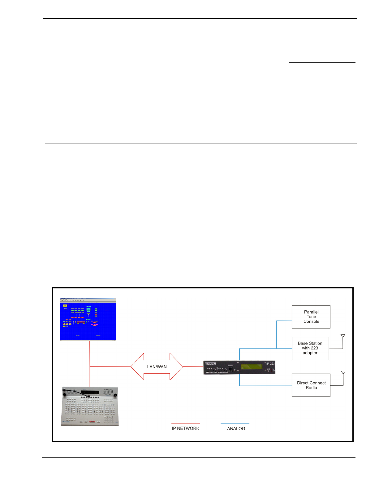
The IP-223 Remote Adapter Panel (IP-223) provides a reliable means of remotely controlling two audio devices. The adapter
has multiple modes allowing it to connect to both digital and analog consoles, and performs a variety of other tasks related to
putting radios on a digital network.
The IP-223 is interconnected to the distant remote control console(s) by means of any available WA N (Wide Area Network) or
LAN (Local Area Network) connection.
Operating Modes
The IP-223 is capable of operating each audio port in different modes:
Local Mode – The radio is connected directly to the IP-223 allowing for simple migration and local control of the radio.
Tone Mode – The IP-223, based on Ethernet traffic, generates the keytones required to control standard industry tone-
equipped radio circuits. This allows an existing tone decoder and radio to be connected. This mode also supports a parallel
analog console for local control.
FIGURE 1. Local and Tone Mode Connections
5
Page 8
Overview
• Ethernet TX and LINK LEDs
• PTT, Monitor, F1 and F2 relays (programmable to any
function tone or revert to F1)
• Four (4) PTT modes and three (3) monitor modes
• Nine selectable PTT frequencies
• 7 digital outputs for channel selection, completely
programmable per function tone
• CTCSS (Continuous Tone Coded Squelch System)
generation (64 frequencies)
• Hardware and software gain control
• Local handset port for monitoring activity and
transmission back to base or to radio
• RS-232C port on rear for initial configuration and
direct radio control
• Single function tone recognition (16 function tones)
• RX (Receive) audio squelch
• Crosspatch capability
• ANI (Automatic Number Identification) over the air –
decode and display
• Provides iDen interface
• Supports Sepura SRM2000, TETRA radio
• E.F. Johnson RS5300 P25 radio interface
• Remote Crosspatch capabilities
• POTS line fail-over
• Phone line interface
• MDC and Fleetsync Decode
• 5/6 Tone signalling encode/decode
• Kenwood radios interface
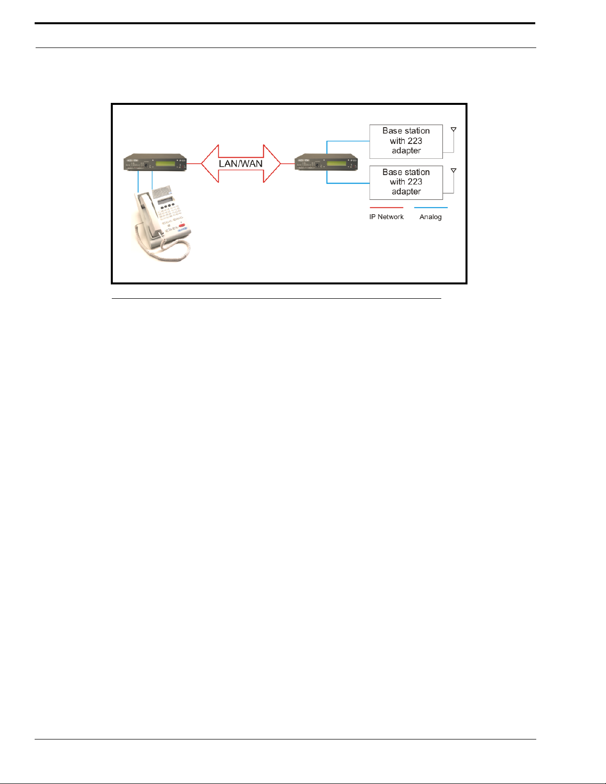
Console Mode – Allows the use of existing tone-based consoles. The IP-223 decodes industry standard tones, converts it
to Ethernet traffic to another IP-223 that regenerates the industry standard tones for control of existing tone remote
adapters.
FIGURE 2. Console Mode Connection
Phone Mode – Using the PIB-223 Phone Interface Box, a line on the IP-223 is used to connect to an analog phone line.
iDen Radio Mode – Using the NI-223, allows interface with a Falcon Class PTT (Push-To-Talk) mobile phone system.
TETRA Radio Mode – Used to interface to a TETRA digital trunked system using the IP-223 and the Sepura SRM2000
mobile radio. The IP-223 interfaces the radio through the PEI (Peripheral Equipment Interface) allowing dispatch access
to TETRA radio assets.
Features
NOTE: The features listed below for the IP-223 version 4.000 do not comprise the full feature set. For more information
on all the features available, contact Radio Dispatch Sales listed on www.telex.com
.
6
Page 9

IP-223 Specifications
NOTE: Transient protection is provided near all audio inputs and outputs. The IP-223 line transformers are not designed
to operate on lines carrying DC (direct current). If a voltage is on the line, isolate with external capacitors. If the
line termination must conduct direct current, install a 600:600-ohm transformer designed for the current
involved.
IP-223 Accessories
There are several optional accessories available for the IP-223:
Part Number Description
223RACK 1 unit high rack shelf to hold up to two IP-223 units
2490248 Alignment Handset
730153 Power Supply
301611000 Fleetsync Over the Air Decode
301611001 MDC Over the Air Decode
PIB223 PIB-223
301912000 NI-223
PRD000003000 IP223 to EFJohnson 5300 Mobile Radio Advanced Control Interface Box
301953000 IP223DB9Splitter - Serial Port splitter cable DB9
301956000 IP223CAB150/180 - IP223-Kenwood TK-150/180 cable
301957000 IP223CAB90 - IP223-Kenwood TK-90 cable
301969000 IP223CABCDM1250 - IP-223-Motorola CDM and GM cable
301961000 IP223CAB2000 - IP-223-Sepura SRM2000 cable
879794 IP223CAB Tone - IP-223-Dual DB25 Tone cable 24ft.
IP-223 Specifications
The specifications for the IP-223 are listed in Table 1. The specifications are subject to change without notice.
TABLE 1. IP-223 Specifications
Operating Temperature Range 0 to 70°C for full specifications
Power Requirements +12 to +16Vdc, semi-regulated, ~700mA
Ethernet Speed 10 BaseT or 100 BaseTX
Lease Lines 2W and 4W supported
Radio Interface ±45VDC withstand rating
Relay Contact Ratings 1A at 125Vac
Non-Relay Outputs Open collector, active low, 200mA maximum, 40V collector to emitter voltage
Radio Input Level 10mVpp to 10Vpp, adjustable
Radio Output Level 10mVpp to 10Vpp for mic level or -40 to +10dBm into 600Ω load, adjustable
Radio Output Impedance 600Ω for balanced mode, 200Ω for single ended mode
Frequency Response ±1.5dB, 300 to 3000Hz
Audio Distortion 2% THD maximum
DTMF Detection Bandwidth ± 25 Hz around center of frequency
MON timer 10ms to 9999ms, adjustable
Dimensions 8 ½” (215.9mm) Wide, 9 3/4” (247.65mm) Deep, by 1 5/8” (41.275mm) High
Actual Weight 3.75lb (1.701kg)
Shipping Weight and Dimensions 5lbs (2.267kg) ~ 12”(304.8mm) x 10”(254mm) x3”(76.2mm)
NOTE: This device is NOT PoE (Power Over Ethernet) compatible.
7
Page 10
Overview
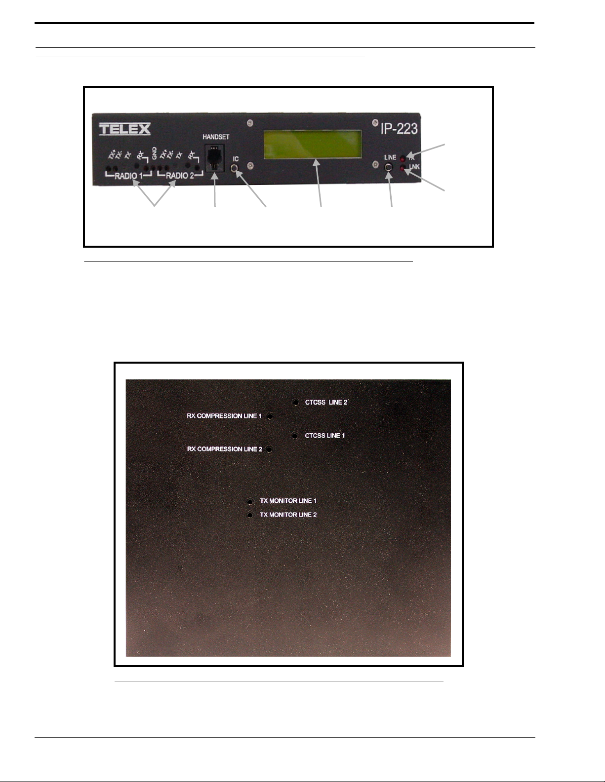
Test and
adjustment points
Handset
jack
LCD displayIC button
Line button
TX LED
LNK LED
Front Panel
FIGURE 3. IP-223 Front Panel
Test and Adjustment Points
Test and adjustment points for radio 1 and radio 2 are provided on the front panel. Newer versions of the IP-223 provide
access to additional test and adjustment points on the case top, as shown in Figure 4.
NOTE: Radio 1 and radio 2 are also referred to as line 1 and line 2 in this manual.
8
FIGURE 4. IP- 2 2 3 C as e Top Test Poin ts
Page 11

Front Panel
Handset Jack
An optional handset is available for the IP-223. When the optional handset is plugged into the handset jack (located on the
front of the unit), the ability to monitor and talk on either line is available. When the handset PTT switch is pressed, the
selected radio connected to the IP-223 is keyed up on the existing frequency and the handset microphone audio is transmitted.
IC Button
The IC button, when pressed, sends audio from the handset microphone back through the IP Network to any console
programmed to monitor the radio circuit.
LCD Display
The LCD display provides panel status information, such as the IP and subnet addresses, line status, and handset line selection.
• TX F# (# is the selected function tone) indicates that a PTT is active.
• RX F# (# is the selected function tone) indicates that the RX radio is active.
• ID # displays when a Fleetsync or MDC ANI ID is decoded. This does not include serial decoding.
• When connected to a serially controlled radio, iDen, Sepura, Kenwood or Johnson displays.
• INTCOM displays when the front panel IC button is pressed.
• EnetIC displays when the console generated intercom is received.
• CTX F# displays when the console mode IP-223 decodes tones from a tone console in Console mode.
• CRX F# displays when the IP-223 transmits wire-line audio to a legacy tone console in Console mode.
• PTX F# displays when the IP-223 decodes tones from a legacy tone console attached in parallel in Tone mode.
• CPT F# displays when the IP-223 transmits to a line if the line-to-line crosspatch is enabled.
• Ring displays when there is an incoming phone call in Phone mode.
• Offhk displays when the line is in use during a phone call.
• LLM displays when no phone line is connected to the PIB-223 in Phone mode.
• NO LINE ENABLED displays after power-up if neither line is enabled.
• Scan List.... displays during power up while the IP-223 is communicating with serial controlled radios that
support the Scan List feature.
To toggle the LCD display, do the following:
1. Press and hold the line button and then momentarily press the IC button.
Three different displays are available with each press of the IC button:
• While pressing the line button, press the IC button once.
The IP address and Mask address of the unit displays.
• Continue to hold the line button, then press the IC button a second time.
The TX alignment tones are turned on.
• Continue to hold the line button, then press the IC button a third time.
The RX VU meter displays.
2. To clear the display and return to the normal LCD display, press the IC button a fourth time.
3. Release the line button.
Line Button
The Line button is used to select which radio, or line, the handset audio is routed and which line is being monitored. The
handset line selection is displayed as an asterisk (*) in the right most column of the LCD display. An asterisk (*) on the top line
of the display indicates a connection to line 1, and an asterisk (*) on the bottom line of the display indicates a connection to
line 2.
9
Page 12
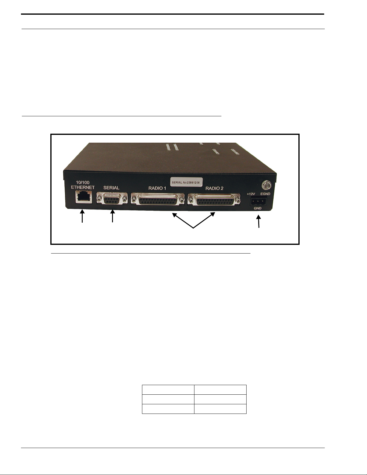
Overview
10/100
Ethernet
connector
Serial
connector
(DB9)
Radio 1 and radio 2
connectors (DB25)
Power
connection
TX LED
The TX LED provides a visual indication the IP-223 is generating IP packets. When the LED is illuminated, packets are being
transmitted to the network.
LNK LED
The LNK LED provides a visual indication of the Ethernet connection. When the LED is illuminated, a valid network
connection has been established.
Back Panel
FIGURE 5. IP-223 Back Panel
10/100 Ethernet Connector
The 10/100 Ethernet connector provides the LAN or WAN connection for the IP-223.
Serial Connector
The serial connector (DB9) is used for either of the following:
• To program an initial IP address into the IP-223 unit, if the IP address cannot be programmed through the
Ethernet port on the installed system.
• To provide serial communication to various radios. Both radio (or line) 1 and radio (or line) 2 are supported on
this connector, with the appropriate splitter cable.
NOTE: You will need to adjust the position of the jumper, (see “To adjust the position of a jumper, do the following:” on
page 15) on J35 when using line 1, or on J26 when using line 2, according to the serial connection type for the
radio interface as shown below:
Jumper position Connection type
A RS-232
B TTL
10
Page 13

Back Panel
SERIAL DB9 PINOUT
SIGNAL LINE # DB9 PIN #
TX 232 1 2
RX 232 1 3
TX TTL 1 9
RX TTL 1 1
Ground both 5
TX 232 2 8
RX 232 2 7
TX TTL 2 4
RX TTL 2 6
Radio 1 and Radio 2 (Line 1 and Line 2) Connectors
Two (2) DB25 connectors are provided for connection to various audio devices. The pinouts are shown in Table 2 when
custom cables need to be fabricated.
Power Connection
The IP-223 requires +12 to +16 VDC, ~700 mA of clean power. A 3-pin screw terminal receptacle is provided on the right rear
of the unit, pin 1 is the positive terminal, pin 2 is the ground terminal, and pin 3 is the earth ground terminal.
As with all communication equipment earth ground should be used. Earth Ground is a low impedance path to Earth for the
purpose of discharging lightening, static, and radiated energy.
11
Page 14
Overview
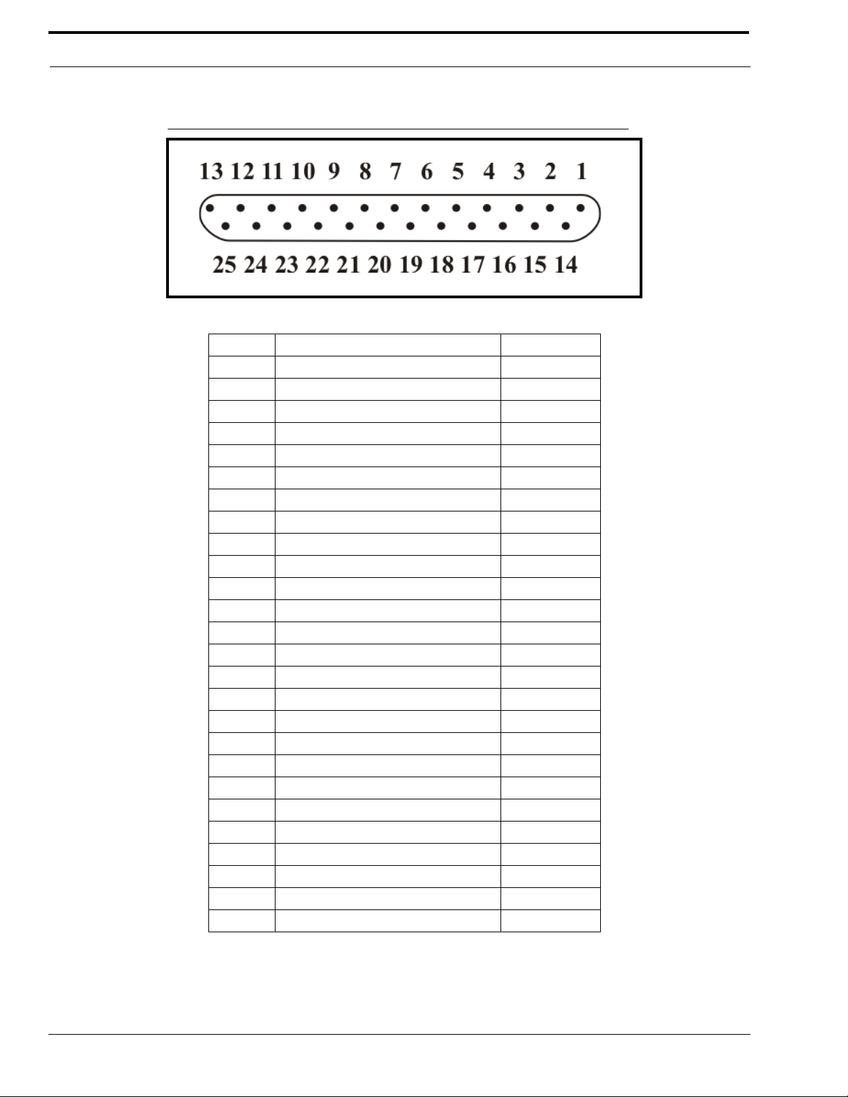
FIGURE 6. DB25 Connector Pinout Configuration
TABLE 2. DB25 Connector Pinout Connections
Pin # Signal Cable color
1 PTT Relay N.C. Brown
2 PTT Relay Common Red
3 MON Relay N.O. Orange
4 R1 Relay N.C. Pink
5 R1 Relay Common Yellow
6 R2 Relay N.O. Green
7 Ground Lt. Green
8 Digital 0/X-Mute Blue
9 Digital 2 Violet
10 Digital 4 Gray
11 CTCSS White
12 Radio RX- in / 4-wire RX Black
13 Radio TX- out / 4-wire TX or 2-wire Brown/White
14 PTT Relay N.O. Red/White
15 MON Relay N.C. Red/Black
16 MON Relay Common Orange/White
17 R1 Relay N.O. Orange/Black
18 R2 Relay N.C. Pink/Black
19 R2 Relay Common Yellow/Black
20 Digital 6/COR Green/White
21 Digital 1/Supervisory Green/Black
22 Digital 3 Blue/White
23 Digital 5/Local PTT Violet/White
24 Radio RX+ input / 4-wire RX Gray/Black
25 Radio TX+ out / 4-wire TX or 2-wire Black/White
Shield Ground
12
Page 15

CHAPTER 2
Communications System Design
Designing an IP-223 system requires an understanding of the radio network and how the various radios and communication
equipment are connected.
The first step in designing an IP-223 system is to create a roadmap of the radio, console, and any other communication
equipment locations. This roadmap must include the following:
• Multicast addresses for each channel of TX (transmit) and RX (receive) communication.
• Port numbers for each channel of TX and RX communication.
• Base IP addresses assigned to each console and IP-223 on the network.
Network Requirements
Bandwidth
Each VoIP channel requires 50kBit of bandwidth while active. Full-duplex conversation (audio in each direction) requires
100kBit of bandwidth.
NOTE: Most radio voice communications are half-duplex (only in one direction at any one time), thus requiring 50kbits.
Some radio systems transmit “go-ahead” beeps when it is clear to talk. In order for the console operator to hear the beeps, the
system must support full-duplex communication. Full-duplex bandwidth may only be required for the first few seconds of a
conversation, due to the brief nature of the “go-ahead” beeps at the beginning of the transmission.
When using a PIB-223, C-6200, or the NI-223 for a telephone connection, 100kBit is required since it is a constant, full-duplex
conversation.
Multicast
In general, Telex systems require multicast to function. The network must be able to create a static multicast address that is
accessible at all times.
It is very common for networks to enable multicast after an IGMP (Internet Group Management Protocol) join message is sent
out, and then “prune” off branches after a period of time. Due to the intermittent usage patterns of two-way radio, such a
system can appear to work flawlessly for a period of time, then no longer work.
13
Page 16

Communications System Design
NOTE: When using Cisco technology, IP PIM dense mode is generally recommended. Generally speaking, sparse-
dense-mode can also be implemented effectively. We recommend explicitly joining the multicast group with an
IP IGMP static-join X.X.X.X command. For more information on Cisco and IGMP, visit www.cisco.com
Internet Group Management Protocol (IGMP)
IGMP can be used to control where multicast is allowed to propagate. When a console on the subnet is expected to be
continually operational, multicast must be active for that subnet at all times.
Network Performance
Networks should perform well under any loading conditions. The default audio delay is 120ms, plus any delay added by the
network. While delay alone does not cause issues, variable delay (jitter) does. Jitter in a network cannot exceed the
maximum packet buffer of any individual product buffer. Refer to the individual product manuals for these specifications. For
example, the IP-223 can handle approximately 600ms of network jitter.
NOTE: Losing more than 5% of the total packets transmitted compromises audio quality and system performance.
Optimally, packet loss should be less than 1%.
14
Page 17
CHAPTER 3
Installation and Level Settings
Local/Radio Connections
NOTE: Connections to radios differ from connections for remote operation; therefore connections are discussed
separately.
Jumper Positions
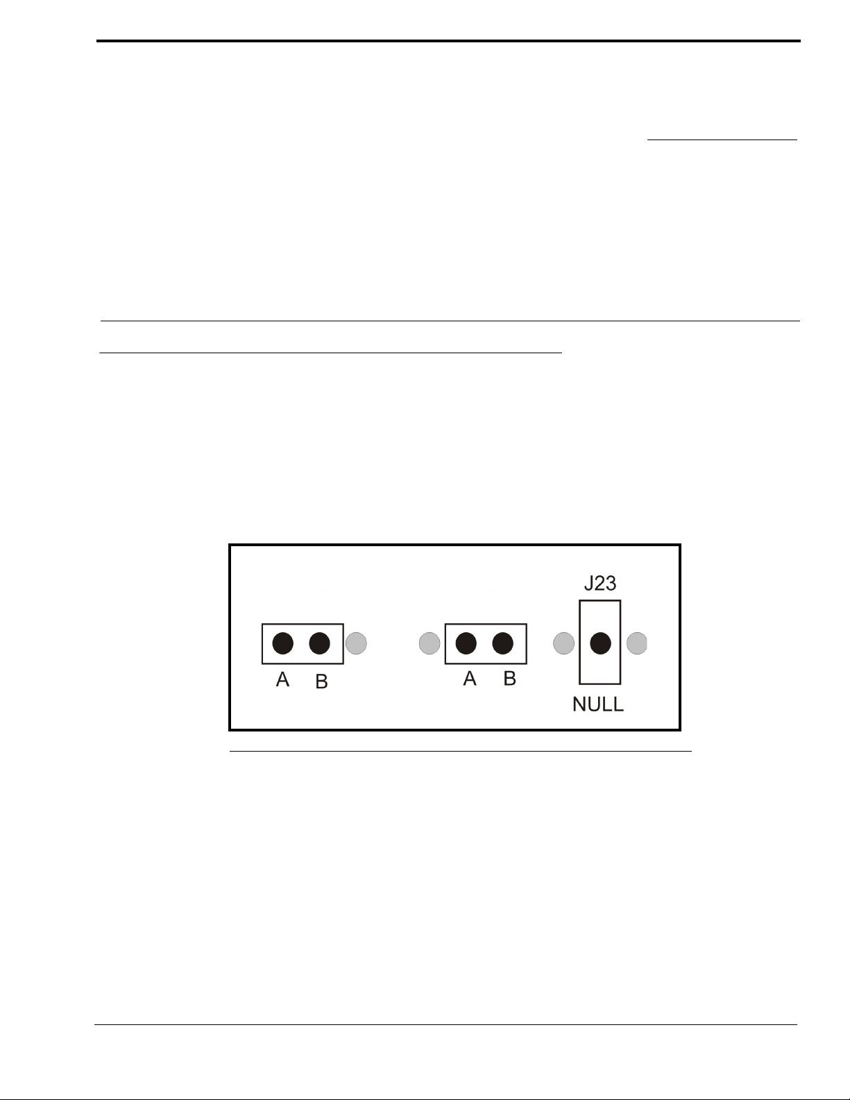
An example of the jumper positions are shown in Figure 7. In the figure, jumper 14 (J14) is shown in position A, jumper 3
(J3) is shown in position B, and jumper 23 (J23) has been hung on the center pin indicating the jumper is in the NULL
position.
FIGURE 7. Jumper Positions
To adjust the position of a jumper, do the following:
1. Remove power from the IP-223 unit.
CAUTION: Failure to remove power may cause damage to the IP-223.
2. Remove the six (6) screws from the case top.
15
Page 18
Installation and Level Settings
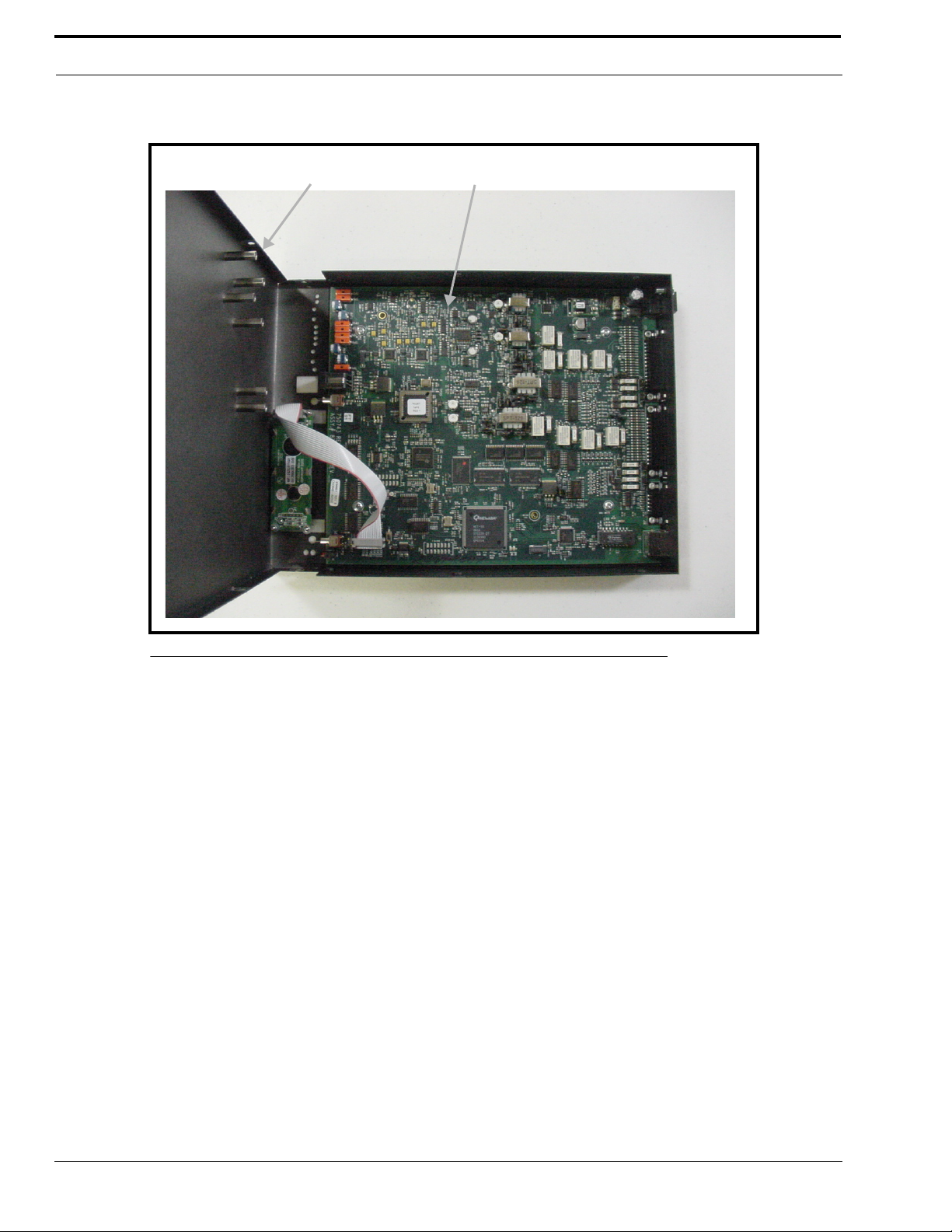
Case top PCB assembly
3. Carefully slide the case top forward past the IC and LINE buttons, and then lift up to gain access to the PCB (Printed
Circuit Board) as shown in Figure 8.
FIGURE 8. IP-223 PCB Assembly
4. Locate the desired jumper on the PCB assembly and use needle nose pliers to adjust the jumper, if necessary.
5. Carefully lift up the case top and place it into position on the chassis bottom.
6. Secure the case top into position using the six (6) screws.
7. Connect power to the IP-223 unit.
16
Page 19

Local/Radio Connections
TX Audio Connection
The IP-223 has a number of options when connecting to the radio. Different jumper settings are required for different
revisions of the PCB installed in the IP-223 unit, and are noted below. Set the jumper position listed for the line according to
the connection type shown below.
If the radio transmit audio output is balanced, connect to pins 13 and 25 of the DB25 connector. If the transmit audio is single
ended, use pin 25 of the DB25 connector.
Shielded cable is recommended.
PCB 750743 or PCB 750630 revision C and higher
Line 1 jumpers: J3, J9, and J11
Line 2 jumpers: J25, J28, and J29
Jumper Position Connection Type
A Single Ended Low-Impedence
B Balanced 600 ohm
RX Audio Connection
To connect the radio receiver audio to the IP-223, several settings are required. Different jumper settings are required for
different revisions of the PCB installed in the IP-223 unit, and are noted below. Set the jumper position on the jumpers listed
for the line according to the connection type shown below.
If the radio receiver audio output is balanced, connect to pins 12 and 24 of the DB25 connector. If the receiver audio is single
ended, use pin 24 of the DB25 connector. The audio source must be after the squelch circuit to prevent sending continuous
noise to the remote console. If a high-impedance point in the receiver is used, a shielded cable is recommended.
PCB 750743 or PCB 750630 revision C and higher
Line 1 jumpers: J16 and J21
Line 2 jumpers: J19 and J20
Jumper Position Connection Type
A Single Ended Low-Impedence
B Balanced 600 ohm
17
Page 20

Installation and Level Settings
Jumper Position
Line 1 Line 2
Receive Input Impedance: J14 J24
8 ohms (for a speaker input) B B
600 ohm A A
10k ohm NULL NULL
NOTE: When the speaker output is used, the radio volume control affects the audio levels of the IP-223.
Jumper Position
Line 1 Line 2
Receive Input Impedance: J14 J23 J17 J24
8 ohms (for a speaker input) B A A B
600 ohm A B B A
10k ohm B B B B
COR (Carrier Operated Relay) I/O (Input/Output)
The ability to control RX packets to the Ethernet is provided at DIG6, pin 20 of the DB25 connector. This overrides LAM
(Line Activity Monitor) control and uses COR from the radio to generate RX packets to the consoles.
PTT Connection
Connect the radio PTT circuit to the PTT relay contact terminals of the panel on the DB25 connector. Usually the common of
the relay contact switch is grounded and the normally open contact connects to the PTT input. An alternative method to ground
the common of the relay internal to the unit is to jumper R377 (line 1) and R381 (line 2) with a piece of wire soldered closed.
Monitor Connection
Connect the radio MON circuit to the MON relay contact terminals of the panel on the DB25 connector. Usually the common
of each relay contact switch is grounded and the normally open contact connects to the MON input. An alternative method to
ground the common of the relay internal to the unit is to jumper R376 (line 1) and R380 (line 2) with a piece of wire soldered
closed.
R1 and R2 Relays
The IP-223 provides two relay closures for controlling the frequency of the radio, or switching a remote ancillary device. The
F1 and F2 contacts can be connected through the DB25 connector. Usually the common of each relay contact switch is
grounded and the normally open contact connects to the radio frequency control terminals. Information on programming the
R1 and R2 relays is provided in the “Setup Information” chapter of this manual starting on page 23. An alternative method to
ground the common of the relay R1 internal to the unit is to jumper R375 (line 1) and R379 (line 2), and for relay R2 jumper
R374 (line 1) and R378 (line 2) with a piece of wire soldered closed.
18
Page 21

Tone/Console Operation
Digital I/O
In addition to the two standard relay closures, seven lines of digital I/O are also included. These lines are open-collector
transistor outputs. They can be programmed on a per line basis to generate any of 128 combinations. They pull to ground and
can be jumper selected to pull up to either +5V or the power supply voltage (minimum +12V). Jumper J8 (line 1) and J30 (line
2) are used to select the pull up voltage. Jumper position A pulls up to +5V and the B jumper position B pulls to the power
supply value. Some radios provide a pull-up voltage. When this occurs, place the jumper into the “null” position. Information
on programming the digital I/O lines is provided in the “Setup Information” chapter of this manual starting on page 23.
CTCSS (Continuous Tone Coded Squelch System) Connection
The IP-223 is programmed with a full range of CTCSS frequencies. Each function tone can be assigned its own CTCSS
frequency for PTT operation, or a number of CTCSS tones can be set using different function tones. This connection is also a
programmable recorder output pin. A single ended, cap coupled, low impedance output is available on pin 11 of the DB25
connector.
Tone/Console Operation
2-/4-Wire Jumper Settings
2-Wire / 4-Wire Selection: Line 1 Line 2
2-Wire A position J33 and J34 J5 and J6
4-Wire B position J33 and J34 J5 and J6
The RX termination J14 (line 1) and J24 (line 2) should be placed in jumper position A on 4-wire systems for a single unit at
the end of a line. If multiple units are connected in parallel, only one unit should have the RX termination jumper in the A
position. The RX termination jumper should be in the NULL position on the rest of the units.
For 2-wire operation:
• PCB 750743 or PCB 750630 revision C and higher - Set J14 or J24 to the NULL position.
TX Side Settings
PCB 750743 or PCB 750630 revision C and higher
Two jumpers on the transmit pair allow a degree of control over the output impedance. The jumper positions for each line,
depending on how many consoles are placed in parallel, are shown below.
Jumper Position
Line 1 Line 2
Consoles in Parallel: J17 J22 J10 J15 Output Impedance
1 BBBB600 ohms
2 A B A B 1200 ohms
3 B A B A 1800 ohms
4 AAAA2400 ohms
Local PTT I/O
The Local PTT I/O is used to generate TX Ethernet traffic on a local keyed system as opposed to the 2175Hz detection on a
tone keyed system. The input is at DIG5; pin 23 of the DB25 connector. The TX condition is caused by an active low.
19
Page 22

Installation and Level Settings
Cross Mute I/O
Cross mute information to local consoles from the Ethernet is provided at DIG0, pin 8 of the DB25 connector.
Supervisory I/O
Supervisory information to and from consoles through the Ethernet is provided at DIG1, pin 21 of the DB25 connector. When
the IP-223 port is in either the console or tone mode with Supervisory enabled, Supervisory ON and OFF packet bursts are
sent to the Ethernet with the sense of logic levels at pin 21 of the IP-223 port. Information on programming the supervisory I/
O is provided in the “Setup Information” chapter of this manual starting on page 23.
The IP-223 provides the following when the ON/OFF burst packets are received from the Ethernet:
Console Mode – Mutes TX traffic from Ethernet to console.
Tone Mode – Pulls the Supervisory line low for control of parallel console control.
Local Mode - No control of the supervisory pin.
Level Adjustments
Once the IP-223 unit is connected to the system, the level potentiometers can be set. Access to test and adjustment points on
newer versions of the IP-223 are provided through labeled openings on the case top and on the front panel of the unit. On older
versions of the IP-223 access to some of the test and adjustment points is provided through labeled openings on the front
panel, however, the case top needs to be opened to access the other test and adjustment points.
General Alignment
The IP-223 has a TX alignment tone and an RX alignment VU meter accessed from the front panel of the unit.
• Press and hold the line button and then momentarily press the IC button twice to generate the 1kHz 0dB TX
alignment tone on both lines.
• Press and hold the line button and then momentarily press the IC button three times to display the RX VU
meters.
Radio/Line TX Level
The Radio 1 TX test points (TP2 and TP6) and the Radio 2 TX test points (TP8 and TP9) are located on the front panel of the
IP-223. These provide a point to measure the actual value being placed into the radio or balanced TX line. The front panel
accessible adjustment Radio 1 TX potentiometer (R47) and Radio 2 RX potentiometer (R61) are used to adjust these levels.
NOTE: If the unit is placed into single-ended mode, the radio TX+ should be measured with respect to ground.
It is also possible to place jumper J9 (line 1) or J26 (line 2) into the “A” position to decrease the output of the TX line by a
factor of 10. The final adjustment should allow for undistorted audio to be transmitted for the full range of transmission levels
at the desired deviation. This can be accomplished by turning on the TX alignment tone and adjusting the TX output to 0dB, as
measured into a 600 ohm load.
20
Page 23

Level Adjustments
Radio/Line RX Level
Standard Alignment Procedure for a 2- or 4- wire System:
• Inject a 0dBm test tone on the RX pair (4-wire pins 12 and 24: 2-wire pins 13 and 25).
• Measure the RX level on test point TP13 for line 1 or TP1 for line 2.
• Adjust potentiometer R175 for line 1 or potentiometer R110 for line 2 until 0dBm is measured between the test
point and GND. (0dBM = 2VPP = .707VRMS)
• Detune slightly 1-2dBm to provide overhead for large transients.
• AGC compression potentiometers RV5 for line 1 and RV1 for line 2 control the aggressiveness of the AGC
circuitry, if enabled. The AGC can be used to enhance the gain capabilities of the RX circuitry. Set RV5/RV1
fully clockwise and, if required, back off 10 to15 degrees maximum.
• Use the RX alignment tool (VU meter) accessed through the LCD display (press and hold the line button and
then momentarily press the IC button 3 times) to verify the dBm level. The reading should be 0dBm with the
AGC turned off. If the AGC is ON, it is likely the RX alignment software will always display 0dBm, the targeted
level for the AGC circuitry.
Line TX Monitor Level (Tone and Console Mode only)
PCB 750743 or PCB 750630 revision C and higher
The Line TX Monitor Level adjustment is used when the IP-223 is connected to consoles set in 4-wire mode. This allows for
local TX audio to be sent back on the Ethernet and played at other consoles so both sides of the radio traffic can be heard. The
alignment for TX monitor is similar to 4-wire RX alignment.
NOTE:
1. The TX Monitor field must be selected in the Options section on the Per Line Setup window.
2. If this feature is not necessary, or the line is in 2-wire mode, the TX Monitor field in the Options section on the Per
Line Setup window should be cleared.
3. Make sure the RX alignment is completed first.
Standard Alignment Procedure for a 4-wire System:
• Inject a 0dBm test tone on the TX audio pairs pins 13 and 25.
• Measure the RX level on test point TP13 for line 1 or TP1 for line 2.
• Adjust potentiometer R390 for line 1 or potentiometer R391 for line 2 until 0dBm is measured between the test
point and GND. (0dBM = 2VPP = .707VRMS)
NOTE: Do not adjust the RX potentiometers.
• Use the RX alignment tool (VU meter) accessed through the LCD display (press and hold the line button and
then momentarily press the IC button 3 times) to verify the dBm level.
CTCSS Level
The CTCSS level is measured by connecting an oscilloscope or RMS meter to ground and Radio 1 CTCSS test point (TP7) or
Radio 2 CTCSS test point (TP10). With the radio connected to the CTCSS output, have the remote console key up so CTCSS
is present. Adjust the Radio 1 CTCSS potentiometer (R50) or Radio 2 CTCSS potentiometer (R53) until the desired level is
achieved.
21
Page 24

Installation and Level Settings
Frequency Decoding
The IP-223 is factory tuned to the frequencies shown below. The detection frequencies cannot be changed as they are coded
into the software. However, any actual function or output can be made to work with any existing programmed frequency.
Please consult the factory for special requirements for frequency selections.
Guard tone/PTT Tone: 2175 Hz
MON Function Tone: 2050 Hz
Frequency Select Function Tones (where used)
F1: 1950 Hz F5: 1550 Hz F9: 1150 Hz F13: 750 Hz
F2: 1850 Hz F6: 1450 Hz F10: 1050 Hz F14: 650 Hz
F3: 1750 Hz F7: 1350 Hz F11: 950 Hz F15: 550 Hz
F4: 1650 Hz F8: 1250 Hz F12: 850 Hz F16: 450 Hz
22
Page 25

CHAPTER 4
Setup Information
The setup information for the IP-223 is accessed by using a web browser, such as Internet Explorer™. This section describes
the programming information for the IP-223. It includes information on setting the IP address, accessing the IP-223 web setup
windows, the setup window standards, and an explanation of the fields on each window used to program the IP-223.
Setting the IP Address Information
Before entering the setup information for the IP-223, the IP address and Network Mask must be assigned to the IP-223 by
the use of a web browser or Windows™ HyperTerminal™ if the assigned IP address is not accessible on your network.Contact
your network administrator to obtain the network IP address and Mask.
For the IP-223 to interface successfully with the LAN or WAN, the IP addresses of the IP-223 and your PC must be on the
same subnet. IP addresses consist of four numbers separated by periods. For example, 10.2.99.101. For more information on
IP Addresses and subnets, consult your network administrator.
In order for the PC and the IP-223 unit to communicate via IP, both devices need to be in the same subnet.
NOTE: For operation on different subnets, a gateway address must be configured.
These IP addresses reside in the same subnet:
PC IP Address: 10.2.99.250
IP-223 IP Address: 10.2.99.251
IP-223 Network Mask: 255.255.255.0
To display the IP address and Network Mask assigned to the IP-223, do the following:
1. Connect power to the IP-223.
2. The IP address and subnet mask are displayed on the LCD momentarily upon power up. To check the IP address and
subnet mask at any other time, press and hold the line button on the front panel of the IP-223, and then momentarily
press the IC button.
The IP address is displayed on the top line of the LCD, and the Network Mask is displayed on the bottom line of the
LCD.
23
Page 26
Setup Information
Verify the IP address and Network Mask obtained from your network administrator to the IP-223 addresses. If any portion of
the first three segments of the IP addresses for the PC and the IP-223 do not match, the IP-223 addresses must be changed to
match the PC subnet.
If the IP address and Mask need to be set up using the serial port, see “Using HyperTerminal” below.
Using HyperTerminal
NOTE: J35 must be in the A position.
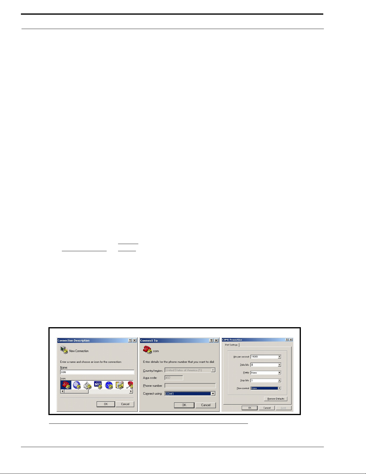
To assign the IP address and Network Mask using HyperTerminal, do the following:
1. Connect the IP-223 to your PC using a DB-9 serial cable.
2. From the Start menu on the computer, open the HyperTerminal Application
(Start|Programs|Accessories|Communications|HyperTerminal).
The HyperTerminal and Connection Description windows appear.
3. In the Name field, enter com.
4. Click OK.
The Connect to window appears.
5. From the Connect using drop-down menu, select COM1.
6. Click OK.
The Com1 Properties window appears.
7. From the Bits per second drop down menu, select 19200.
8. From the Flow Control drop down menu, select None
NOTE: These parameters may be different than the defaults depending on the Per Line 1 Serial Setup page.
Default
Drop-down menu
Setting
Bits per second field: 19200
Data bits field: 8
Parity field: None
Stop bits field: 1
Flow control field: None
9. Click OK.
The Main HyperTerminal window appears.
24
FIGURE 9. Com Terminal Setup windows
Page 27
Setting the IP Address Information
C
D
A
B
E
F
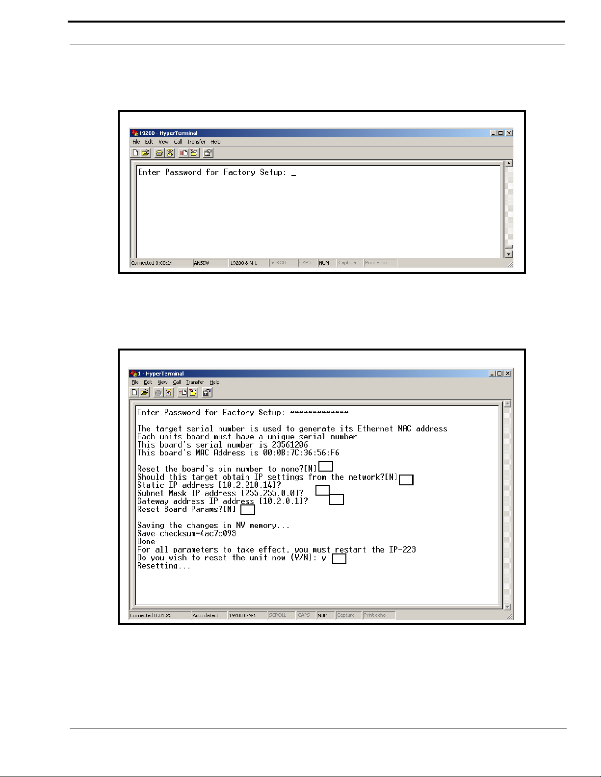
10. In the main HyperTerminal window, type an uppercase S
11. Press ENTER.
Enter Password for Factory Setup appears.
FIGURE 10. HyperTerminal Window Password
12. Type technobabble for the factory setup password.
13. Press ENTER.
The serial port access window shown in Figure 11 appears.
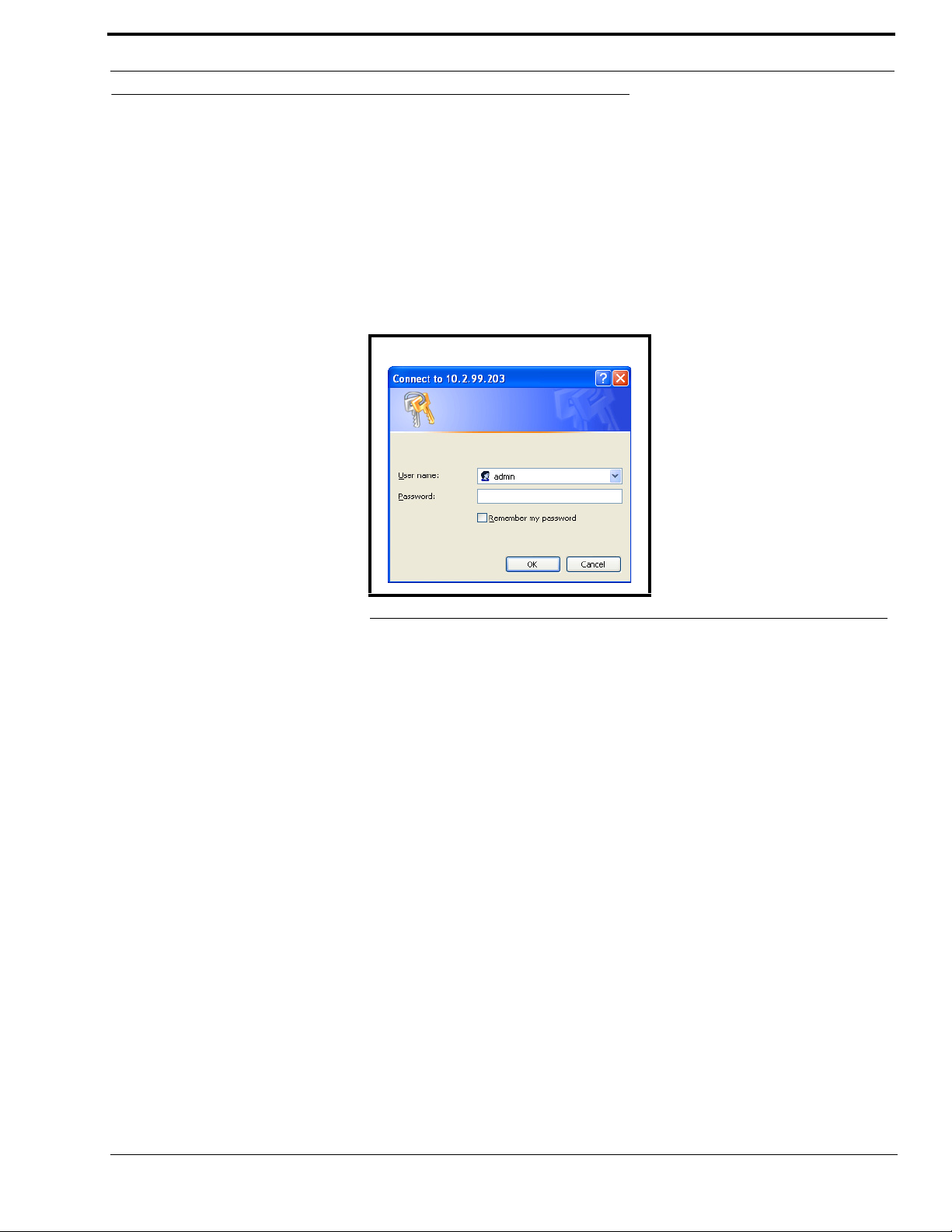
FIGURE 11. HyperTerminal Factory Setup Options – Serial Port Access window
NOTE: The serial number is fixed and should match the case label. The MAC (Media Access Control) address is
generated based on the serial number.
25
Page 28

Setup Information
The following is a brief explanation of the factory setup options shown in Figure 11:
A = Allows access to the PIN number if it is new or forgotten.
B = Allows the unit to get an IP address via DHCP, or to manually set the IP address.
C = Allows the Subnet Mask to be manually entered or changed.
D = Allows the Gateway address to be manually entered or changed.
E = Provides the ability to reset (back to defaults) the Board Parameters
F = Provides the ability to reset the unit.
14. When Reset the Board’s Pin Number to None appears, type Y to reset the board’s pin number to none, otherwise,
select N.
15. Press Enter.
16. When Should this target obtain IP settings from the network appears, type Y to obtain the IP settings from the
network, otherwise, select N.
17. Press Enter.
18. When Static IP address appears, enter the IP address of the IP-223, if necessary.
19. Press Enter.
20. When Subnet Mask IP address appears, enter the Subnet Mask IP address, if necessary.
21. Press Enter.
22. When Gateway address IP address appears, enter the Gateway IP address, if necessary.
23. Press Enter.
24. When Reset Board Params appears, type Y to reset the board parameters, otherwise type N.
25. Press Enter.
26. When “Do you wish to reset the unit now” appears, type Y if changes were made on the window, otherwise enter an
N.
27. If changes were made on the window, press ENTER to reset the IP-223, otherwise proceed to the next step.
The changes made are saved to memory.
28. Close the HyperTerminal program.
26
Page 29
Accessing the IP-223 Web Setup Windows
Accessing the IP-223 Web Setup Windows
Before connecting the IP-223 to the web browser, an IP address compatible with an existing network must be set. Details on
setting the IP address and Network Mask are described earlier in “Setting the IP Address Information” on page 23.
The configured IP address is the web browser address (http://XXX.XXX.XXX.XXX, the XXX’s refer to the values for the
assigned IP address) used to access the IP-223 Web Setup windows.
To access the IP-223 web setup windows, do the following:
1. Open the web browser on the PC.
2. Enter the IP address of the IP-223 in the web address bar.
The Connect to [IP Address] window shown in Figure 12 appears.
FIGURE 12. Connect to [IP Address] window
3. From the User Name drop-down menu, enter admin.
4. In the Password field, enter the appropriate PIN.
If this is the first time the IP-223 has been started and a PIN has not been assigned to the unit, no entry is required.
5. Click OK.
The Welcome window appears.
27
Page 30

Setup Information
IP-223 Web Setup Windows Standards
Links
Across the top of each setup window are links used to access the various IP-223 configuration pages. On the left side of the
links header, the name assigned to the unit, the MAC address, and the version number of the firmware are displayed. A brief
description of each link is provided below.
FIGURE 13. IP-223 Links
Link Description
Displays the Welcome window described on page 30.
Displays the Basic Ethernet Setup window described on page 31.
Displays the General Gain Setup window described on page 34.
Displays the Multicast Port Number Setup window described on page 35.
28
Displays the Per Line Setup - [Line X] window described on page 38.
Page 31

IP-223 Web Setup Windows Standards
Displays the Save to EEPROM Command Buttons window described on page 54.
Displays the Additional Feature Setup window described on page 56.
Displays the Retrieve Configuration Data from Remote IP-223 window described on page 57.
Displays the Crosspatch Setup window described on page 58.
Displays the Remote CrossPatch Pin Setup window described on page 63.
Displays the “admin” Account PIN Change window described on page 65.
Displays the Tone Frequency and Durations window described on page 66.
To access a setup window, do the following:
> Click the desired link.
The window for the selected link appears.
Submit Button
Moving from one window to the next does not save any data entered in the window. To save changes made to the entries on a
window, there is a submit button provided at the bottom of each window. For ease of use, a submit button is also
provided at the top of the window when the setup window is too long to display on the computer screen. Selecting the submit
button sends the entries currently displayed on the window to the IP-223 for storage. The data is not stored in permanent
memory until it is saved as explained in “Save to EEPROM” on page 54.
29
Page 32

Setup Information
Welcome Window
Clicking the picture of the IP-223 on the links displays the Welcome window, shown in Figure 14. The Welcome window
provides a basic description of the IP-223 operating modes and a field to enter a descriptive name for the unit. This name is
displayed at the top of each IP-223 web setup window.
FIGURE 14. Welcome window
To change the name of the IP-223 unit, do the following:
1. In the field provided on the window, enter the desired name (up to 12 characters).
2. Click Submit.
The name appears at the top of the setup window.
3. From the links, select Save to EEPROM.
The Save Setup Parameters window appears.
4. Click Save Current Parameters.
The changes made are saved to permanent memory.
30
Page 33

Basic Ethernet Setup
Basic Ethernet Setup
Click Basic Ethernet Setup to display the Basic Ethernet Setup window, shown in Figure 15. The Basic Ethernet Setup
window is used to configure the IP-223 for use. The fields on this window are described on the following pages.
FIGURE 15. Basic Ethernet Setup window
Use DHCP Server Check Box
The Use DHCP Server check box indicates whether or not DHCP (Dynamic Host Configuration Protocol) is used. If
selected, DHCP allows the IP-223 to acquire all of the information for operation on the network bypassing its manual entry.
NOTE: Telex does not recommend operating with DHCP enabled. Operating with DHCP enabled may cause the base IP
address to change unexpectedly making changes to the software setup more difficult. If employing 5/6-tone
selective calling and messaging, DHCP must not be used.
Unit IP Address Field
The Unit IP Address field identifies the unique base address assigned to the IP-223. This address identifies the unit for
operations such as setup, software upgrades and communications in some operating modes.
31
Page 34

Setup Information
Subnet Mask Field
The Subnet Mask field identifies information used by the IP stack to determine if an IP address is local or if an IP address
requires the use of a gateway to be reached. Contact your network administrator to obtain the proper value for this field.
Gateway Address Field
The Gateway Address field identifies the IP address of the node used to reach other networks. Contact your network
administrator to obtain the proper value for this field.
DNS (Domain Name Server) Number 1-3 Fields
The DNS Number fields are currently not used by the IP-223.
Unit Name Field
The Unit Name field is used to enter a descriptive name for the unit. This name is displayed at the top of each IP-223 web
setup window. The unit name entry cannot exceed 12 characters.
NOTE: You can also set the Unit Name from the Welcome Page, see “Welcome Window” on page 30.
Packet Delay before Playback Field
The Packet Delay before Playback field identifies the length of delay before playback (jitter buffer). The IP-223 utilizes a
20ms UDP/IP (User Datagram Protocol/Internet Protocol) packet to encode audio. Some buffering of these packets must
occur before playback to help absorb network delays, jitters, and lost packets. The typical entry for this field is 6, which
translates to a delay of 120ms before playback (each packet is 20ms of audio). Larger values may be required for complicated
networks, and smaller values for less complicated networks.
The variable range for this field is 4 to 29.
QOS (Quality of Service): Precedence Bits Field
The QOS: Precedence Bits field is used to set the priority level of network traffic. Typically this value is left at 0 for normal
traffic and 5 for voice traffic.
The variable range for this field is 0 to 7.
QOS: D, T, and R (Delay, Throughput, and Reliability) Bits Field
The QOS: D, T and R Bits field is used for advanced programming purposes. These bits are usually 0. Contact your network
administrator to obtain the appropriate value for this field.
Delay (D) an active delay bit tells the router to choose a high speed to minimize delay
Throughput (T) an active throughput bit specifies high capacity links should be used.
Routing (R) an active routing bit directs routing protocols and network management applications to select
fault-tolerant paths.
For information on the binary equivalent for delay, throughput, and reliability see Table 3 on page 33.
The variable range for this field is 0 to 7.
32
Page 35

Basic Ethernet Setup
TABLE 3. D, T, R Binary Reference
Precedence Field D, T, and R bits
Binary Traf f i c Ty p e Binary
0 0 0 (0) Best Effort D T R
0 0 1 (1) Background 0 0 0 (0) Normal (Best Effort), minimal cost
0 1 0 (2) Standard 0 0 1 (1) Maximize Reliability
0 1 1 (3) Excellent Load 0 1 0 (2) Maximize Throughput
1 0 0 (4) Controlled Load 1 0 0 (4) Minimize Delay
1 0 1 (5) Video
1 1 0 (6) Voice
1 1 1 (7) Network Control
Local Computer IP Address 1-10 Fields
The Local Computer IP Address fields identify the base IP address of up to ten IP-223 units within the same room. These
fields are generally used when the selected line mode is console. The entries are used for the Ethernet crossmute function. The
IP-223 examines the source of the audio and flags it if the source was from one of the IP-223 units listed in these fields.
To configure the IP-223 for use, do the following:
1. From the links, select Basic Ethernet Setup.
The Basic Ethernet Setup window appears.
2. In the Unit IP Address field, enter the IP address.
3. In the Subnet Mask field, enter the subnet mask address.
4. In the Gateway Address field, enter the gateway address, if required.
5. In the Unit Name field, enter a descriptive name.
6. In the Packet Delay before Playback field, enter the number of packets of delay for playback (each packet is 20ms of
audio).
7. In the QOS: Precendence Bits field, enter the number of bits, if required.
8. In the QOS: D, T, and R Bits field, enter the number of bits, if required.
9. In the Local Computer IP Address fields, enter the IP addresses of the IP-223 units that are located in the same room.
10. Click Submit.
The entries currently displayed on the window are sent to the IP-223 for storage.
11. From the links, select Save to EEPROM.
The Save Setup Parameters window appears.
12. Click Save Current Parameters.
The entries are saved to permanent memory.
33
Page 36

Setup Information
General Gain Setup
Click General Gain Setup to display the General Gain Setup window, shown in Figure 16. The IP-223 is based largely on
software controlled resistors with a resolution of 1.5dB per step. This window provides for an up or down adjustment of the
gain levels for various parameters included on the window. For example, if it is determined the output level for a transmission
line is 3.0dB too high, an entry of -3.0dB should be entered in the corresponding Transmit Gain field for the line.
FIGURE 16. General Gain Setup window
Handset Mic Gain Drop-Down Menu
The Handset Mic Gain drop-down menu identifies the level, in dB, of gain for the handset mic. The values for this field are:
12.0, 10.5, 9.0, 7.5, 6.0, 4.5, 3.0, 1.5, 0, -1.5, -3.0, -4.5, -10, -16, -22, -28, and -34.
Handset Sidetone Gain Drop-Down Menu
The Handset Sidetone Gain drop-down menu identifies the sidetone gain level, in dB, for the handset. The values for this
field are: -12, -14, -16, -18, -20, -22, -24, and MUTE.
Receive Gain Drop-Down Menu
The Receive Gain drop-down menu identifies the receive gain, in dB, for either line 1 or line 2. The values for this field are:
12.0, 10.5, 9.0, 7.5, 6.0, 4.5, 3.0, 1.5, 0, -1.5, -3.0, -4.5, -10, -16, -22, -28, and -34.
Transmit Gain Drop-Down Menu
The Transmit Gain drop-down menu identifies the transmit gain, in dB, for either line 1 or line 2. The values for this field are:
12.0, 10.5, 9.0, 7.5, 6.0, 4.5, 3.0, 1.5, 0, -1.5, -3.0, -4.5, -10, -16, -22, -28, and -34.
CTCSS Gain Drop-Down Menu
The CTCSS Gain drop-down menu identifies the CTCSS gain, in dB, for either line 1 or line 2. The values for this field are:
12.0, 10.5, 9.0, 7.5, 6.0, 4.5, 3.0, 1.5, 0, -1.5, -3.0, -4.5, -10, -16, -22, -28, and -34.
TX Voice Gain Field
The TX Voice Gain field allows you to set the transmit voice gain, in dB, for either line 1 or line 2. The field value can range
from 10dB to -60dB.
34
Page 37

Multicast Address Setup
To adjust a signal level, do the following:
1. From the links, select General Gain Setup.
The General Gain Setup window appears.
2. From the Handset Mic Gain drop-down menu, select the desired gain for the handset mic.
3. From the Headset Sidetone drop-down menu, select the desired gain for the headset sidetone.
4. From the Receive Gain drop-down menu, select the desired receive gain for the appropriate line.
5. From the Transmit Gain drop-down menu, select the desired transmit gain for the appropriate line.
6. From the CTCSS Gain drop-down menu, select the desired CTCSS gain for the appropriate line.
7. In the Tx Voice Gain field, enter the desired gain for the appropriate, if required.
8. Click Submit.
The entries currently displayed on the window are sent to the IP-223 for storage.
9. From the links, click Save to EEPROM.
The Save Setup Parameters window appears.
10. Click Save Current Parameters.
The entries are saved to permanent memory.
Multicast Address Setup
Click Multicast Address Setup to display the Multicast Port Number Setup window, shown in Figure 17. The Multicast Port
Number Setup window identifies the mode of operation or channel type, as well as which port the IP-223 uses to
communicate various channel information on. Once a selection is made in the channel type field, the fields necessary to enter
the setup information for the selected channel type are enabled. The fields on this window are described on the following
pages.
FIGURE 17. Multicast Port Number Setup window
Channel Number Field
The Channel Number field displays the appropriate channel number for the specified parameters.
Enable via Ethernet Check Box
The Enable via Ethernet check box indicates whether or not Ethernet connectivity is used for the channel number. If selected,
Ethernet connectivity is ON. Otherwise, audio received from the analog connections of the IP-223 are not echoed to the
Ethernet, and Ethernet traffic is not mixed into the audio of the IP-223.
35
Page 38

Setup Information
When Tape 1 is enabled, a separate stream is created with both RX and TX audio for that line. When Tape 2 is enabled, a
separate Ethernet stream is created with both RX and TX audio for that line. This stream can then be recorded by a Telex
Network Recorder.
The Phone check box must be selected if any line on the IP-223 is defined as a phone line.
Channel Type Drop-Down Menu
The Channel Type drop-down menu identifies the operating mode for channel number 1 and 2. The channel type for all other
operating modes are displayed on the window. Selection of the channel type enables the fields necessary to enter the setup
information for the selected channel type. The operating modes available are:
Local Mode – The radio is connected directly to the IP-223 allowing for simple migration and full local
control of the radio.
Tone Mode – The IP-223, based on Ethernet traffic, generates the keytones required to control standard,
tone-equipped radio circuit. This allows an existing tone decoder and radio to be connected.
This mode also supports a parallel analog console for local control.
Console Mode – Allows the use of existing tone-based consoles to the VoIP network. The IP-223 decodes
standard tones, converts it into Ethernet traffic for another IP-223.
Phone Mode – Using the PIB-223 (phone interface box), a line on the IP-223 is used to connect to an analog
phone line.
iDen Radio – Using the NI-223, allows interface with a Falcon Class push-to-talk (PTT) mobile phone
system.
TETRA Radio Mode – Used to interface to a TETRA digital trunked system using the IP-223 and the Sepura
SRM2000 mobile radio. The IP-223 interfaces the radio through the PEI allowing dispatch
access to TETRA radio assets.
Channel Name Field
The Channel Name field is used to enter a descriptive name, up to 12 characters, for the channel number.
Multicast Address Fields
The Multicast Address field identifies the broadcast address for all audio traffic specific to a channel. To inter-operate, all
consoles must have the same base multicast address.
The variable range for this field is 224.0.0.2 to 239.255.255.255.
The entry in the first Multicast Address field applies to the port number entered in the RX Port field. The entry in the second
Multicast Address field applies to the port number entered in the TX Port field. The option to use a different multicast address
for the RX port is available. This provides flexibility and acts as a filter.
NOTE: IP-223s can also operate Unicast (point-to-point), these fields can support class A, B, and C addresses.
In Phone Mode, the multicast address is not as important because the console is connected via a TCP/IP socket.
NOTE: Make sure the RX and TX port numbers are unique.
The entry for a ring signal must be a unique multicast address and different from the other channels.
36
Page 39

Multicast Address Setup
RX and TX Port Fields
The RX and TX Port fields identify the port number for each channel. The port number must be unique, per channel, and
must be greater than 1054. For example, based on the entries shown in Figure 17, all consoles must have a multicast address of
225.8.11.81 and an RX port number of 1056 to monitor RX audio for channel 1 and a TX port number of 1074 to monitor TX
audio for channel 1.
TX Group Port Field
The TX Group Port field is used to transmit to multiple IP-223s based on a unique port number.
Channel Hops Field
The Channel Hops field identifies the number of routers the multicast audio packets go through before being stopped. Your
specific network design dictates this value. If audio is not reaching a particular node on the network, increasing this value may
correct the problem. You may know this value as TTL (Time To Live)
The variable range for this field is 1 to 128.
To define the parameters for a channel number, do the following:
NOTE: The following procedure outlines the entries required for each field on the Multicast Port Number Setup window.
Depending on the channel type selected, all entries listed may not be required or available for the channel type.
1. From the links, select Multicast Address Setup.
The Multicast Port Number Setup window appears.
2. Select the Enable via Ethernet check box, if Ethernet connectivity is used.
3. From the Channel type drop-down menu, select the operating mode.
4. In the Channel Name field, enter a descriptive name for the channel.
5. In the first Multicast Address field, enter the multicast address for the RX port.
6. In the RX Port field, enter a unique RX port number.
7. In the second Multicast Address field, enter the multicast address for the TX port.
8. In the TX Port field, enter a unique TX port number.
9. In the TX Group Port field, enter the TX group port number, if applicable.
10. In the Channel Hops field, enter the number of routers (channel hops) the multicast audio packets can go through
before being stopped.
11. Click Submit.
The entries currently displayed on the window are sent to the IP-223 for storage.
12. From the links, select Save to EEPROM.
The Save Setup Parameters window appears.
13. Click Save Current Parameters.
The entries are saved to permanent memory.
37
Page 40

Setup Information
Per Line Setup
Click Per Line Setup to display the Per Line Setup window, shown in Figure 18. The Per Line Setup window identifies the
parameters for the channel type selected for the line number on the Multicast Port Number Setup window described on
page 35. The line number to which the details on the window apply is displayed at the top of the window. The channel type
selected determines the window displayed and enables the appropriate fields on the window necessary to enter the setup
information for the channel type. The fields on this window are described on the following pages.
FIGURE 18. Per Line Setup - [Line] window (Local Mode shown)
NOTE: Field selection may vary depending upon line type.
38
Page 41

Per Line Setup
Command Buttons
NOTE: If any changes have been made to the entries on the window, click the Submit button before going to a new page
or window. If the Submit button is not selected before the selection of another command button, any changes
made to the entries on the window are cleared.
Prev Tones Button
Select the Prev Tones button to toggle the window between function tones 1 and 100.
Line 1 Button
Select the Line 1 button to change the window to the Per Line Setup - Line 1 window.
Line 2 Button
Select the Line 2 button to change the window to the Per Line Setup - Line 2 window.
Next Tones Button
Select the Next Tones button to toggle the window between function tones 1 and 100.
Port Enabled Check Box
The Port Enabled check box indicates whether or not the port is enabled. If selected, the port is enabled and selection of
transmission or play received audio is allowed.
Line Mode Status Field
The Line Mode Status field displays the channel type selected for the line on the Multicast Port Number Setup window
described on page 35.
PTT Relay Field
The PTT Relay field allows a secondary external function to be controlled with a separate relay closure at the same time as the
PTT relay. Select one of the following:
PTT relay only – When selected, only the PTT relay is closed. (Default Setting)
PTT + R1 – When selected, both the PTT relay and the R1 relay close at the same time.
PTT + R2 – When selected, both the PTT relay and the R2 relay close at the same time.
PTT + BOTH – When selected, the PTT relay, the R1 relay, and the R2 relay close at the same time.
39
Page 42

Setup Information
Monitor Relay Field
The Monitor Relay field provides the IP-223 the ability to decode a valid Ethernet packet and provide a relay-contact output
to turn off the sub-audible-tone-decoder circuit in the radio receiver. This allows the console operator to monitor the channel
for other users before transmission (required by FCC regulations on stations equipped with CTCSS). Select one of the
following operating modes for the monitor relay:
Reset with PTT – When selected, the monitor relay is closed from the time the monitor tone sequence is received
until the next PTT operation.
On except PTT – When selected, the monitor relay is latched at all times except when PTT is active, whether the
monitor function tone is received or not.
Timed – When selected, enter the amount of time, in ms, the monitor relay is latched.
Serial Port Mode Drop-Down Menu
The Serial Port Mode drop-down menu identifies the specific radio interface for the serial port configuration. Selecting an
item with a Scan List suffix enables a frequency scan list update function. The freq scan list function synchronizes the console
scan list with the radio’s scan list. The selections in the drop-down menu for the Local mode channel type are shown in
Figure 19.
Serial Port Params Drop-Down Menu
The Serial Port Params drop-down menu identifies the configuration of the serial port data speed and format. The default
setting for the field is 19200,N,8,1. If necessary, refer to the Radio Dispatch & Signaling Equipment downloads available on
the Telex website (www.telex.com) for this setting based on the radio to be installed. The selections in the drop-down menu
for the Local mode channel type are shown in Figure 19. Serial port parameters refer to bit rate, parity, data bits, and stop bits.
FIGURE 19. Serial Port drop-down menu selections (Local Mode Shown)
Function Tone [Enable] Check Box
The Function Tone [Enable] check box indicates whether or not the function tone is active. If selected, the function tone is
active. The frequency for the tone is set on the Tone Frequency and Durations window described on page 66. The standard
function tones and their frequencies are the default entries. These entries are shown in Table 7 on page 67.
NOTE: At least one function tone must be selected.
40
Page 43

Per Line Setup
Relay Drop-Down Menu
The Relay drop-down menu identifies the relay(s), if any,
closed immediately upon receipt of the function tone. The
selections available are: no selection, R01, R02, or BOTH.
Relay Group Drop-Down Menu
The Relay Group drop-down menu identifies if a relay is
grouped into separate functions. This allows more than one
relay to be activated at any particular time by being in
separate groups. For example, when F1 has R1 selected as its
relay, and F2 has R2 selected as its relay, setting the two
Relay Group numbers to the same value allows multiple
relays with different functions. In this scenario, the relays for
F1 and F2 are interlocked. When the Relay Group assigned
to F1 and F2 are different, R2 does not activate when F1 is
received. Furthermore, when there is no relay selected for a
function tone, but the assigned relay group is used by
another relay group, when the function tone is received, all
relays in the group are activated. This allows relay R1 and
R2 to be assigned to different groups and use other function
tones within the same relay group to activate them.
Select either 1 or 2 from the drop-down menu.
Relay Time (ms) Field
The Relay Time (ms) field identifies if the selected relay(s)
latch ON when the function tone is received, or if the
selected relay(s) is latched ON for a specified period of time
when the function tone is received. To program the relay(s)
to latch ON when the function tone is received enter a zero
(0) in the field. To set the duration the relay(s) is latched ON,
enter the desired amount of time, in ms, in the field.
The variable range for this field is 0 to 32000.
Digital Output Field
The Digital Output field identifies the DIG0-DIG6 output
for the function tone. Enter the numeric value shown in the
Value column in Table 4 for the desired DIG0-DIG6 output.
The variable range for this field is 0 to 127.
NOTE: Using DIG6 for COR input limits the digital
output value from 0 to 63
.
TABL E 4 . Digital Output Values
DIG6
DIG5
DIG4
DIG3
DIG2
Val ue
LLLLLLL
0
LLLLLLH
1
LLLLLHL
2
LLLLLHH
3
LLLLHLL
4
LLLLHLH
5
LLLLHHL
6
LLLLHHH
7
LLLHLLL
8
LLLHLLH
9
LLLHLHL
10
LLLHLHH
11
LLLHHLL
12
LLLHHLH
13
LLLHHHL
14
LL LHHHH
15
LLHLLLL
16
LLHLLLH
17
LLHLLHL
18
LLHLLHH
19
LLHLHL L
20
LLHLHLH
21
LLHLHHL
22
LLH LHHH
23
LLHHLLL
24
LLHHLLH
25
LLHHLHL
26
LLHHLHH
27
LLHHH L L
28
LLHHH LH
29
LLHHHH L
30
LLHHHHH
31
LHLLLLL
32
33LHLLL LH
34LHLLL HL
35LHLLL HH
36 L H L L H L L
37 L H L L H L H
38 L H L L H H L
39L H L L H HH
40LHLHL LL
DIG1
DIG0
41
Page 44

Setup Information
TABL E 4 .
41LHLHL LH
42LHLHL HL
43LHLHL HH
44LHLHH LL
45LHLHH LH
46LHLHH HL
47LHLHH HH
48 L H H L L L L
49 L H H L L L H
50 L H H L L H L
51 L H H L L H H
52 L H H L H L L
53 L H H L H L H
54 L H H L H H L
55L H H L H HH
56LHHHL LL
57LHHHL LH
58LHHHL HL
59LHHHL HH
60LHHHH LL
61LHHHH LH
62LHHHH HL
63LHHHH HH
64HLLLL LL
65HLLLL LH
66HLLLLHL
67HLLLLHH
68HLLLHLL
69HLLLHLH
70HLLLHHL
71HLLLHHH
72HLLHLLL
73 H L L H L L H
74HLLHLHL
75HLLHLHH
76HLLHHLL
77HLLHHLH
78HL L HHHL
79HL L HHHH
80HLHLLLL
81HLHLL LH
82HLHLLHL
83HLHLLHH
84HLHLHLL
85HLHLHLH
Digital Output Values
DIG6
Val ue
DIG5
DIG4
DIG3
DIG2
DIG1
DIG0
TABLE 4.
86HLHLHHL
87HLHLHHH
88 H L H H L L L
89 H L H H L L H
90 H L H H L H L
91 H L H H L H H
92HLHHHL L
93HLHHHL H
94HLHHHHL
95HLHHHHH
96HHLLLLL
97HHLLL LH
98HHLLL HL
99HHLLL HH
100 H H L L H L L
101 H H L L H L H
102 H H L L H H L
103 H H L L H H H
104HHLHL LL
105HHLHL LH
106HHLHL HL
107HHLHL HH
108 H H L H H L L
109 H H L H H L H
110 H H L H H H L
111 H H L H H H H
112HHHL L LL
113HHHL L LH
114HHHL L HL
115HHHL L HH
116HHHLH LL
117HHHLH LH
118HHHLH HL
119HHHLH HH
120HHHHL LL
121HHHHL LH
122HHHHL HL
123HHHHL HH
124HHHHH LL
125HHHHH LH
126HHHHH HL
127HHHHH HH
128HLLLLHL
Digital Output Values
DIG6
Val ue
DIG5
DIG4
DIG3
DIG2
DIG1
H=high (on), L=low (off)
DIG0
42
Page 45

Per Line Setup
CTCSS Freq Field
The CTCSS Freq field identifies the CTCSS tone frequency set for the function tone. Enter the desired Tone Number shown
in Table 5. If zero (0) is entered, there is no CTCSS tone frequency set for the function tone.
TABLE 5. CTCSS Tone Frequencies
Ton e
Number
1 33.0 17 71.9 33 123.0 49 183.5
2 35.4 18 74.4 34 127.3 50 186.2
3 36.6 19 77.0 35 131.8 51 189.9
4 37.9 20 79.7 36 136.5 52 192.8
5 39.6 21 82.5 37 141.3 53 196.6
6 44.4 22 85.4 38 146.2 54 199.5
7 47.5 23 88.5 39 151.4 55 203.5
8 49.2 24 91.5 40 156.7 56 206.5
9 51.2 25 94.8 41 159.8 57 210.7
10 53.0 26 97.4 42 162.2 58 218.1
11 54.9 27 100.0 43 165.5 59 225.7
12 56.8 28 103.5 44 167.9 60 229.1
13 58.8 29 107.2 45 171.3 61 233.6
14 63.0 30 110.9 46 173.8 62 241.8
15 67.0 31 114.8 47 177.3 63 250.3
16 69.4 32 118.8 48 179.9 64 254.1
Freq.
(Hz)
Ton e
Number
Freq.
(Hz)
To ne
Number
Freq.
(Hz)
Ton e
Number
Freq.
(Hz)
CTCSS Default Check Box
The CTCSS Default check box indicates whether or not the entry in the CTCSS Freq field is ignored and the last selected
value is generated during PTT. For example, F1 is used for all transmissions and CTCSS Default is selected for F1. F2-F8 have
different CTCSS values programmed for them and the CTCSS Default check box is cleared. Selecting F2 and then keying up
on F1 sets the CTCSS tone to the F2 value. Selecting F4 sets the CTCSS tone to the F4 value. When PTT is pressed, F1 is the
default frequency and the F4 CTCSS tone is sent.
System Field (or Zone when attached to an EFJ device)
The System field identifies the system or zone for serial controlled radios. This option is available only in Local Mode.
Chan Field
The Chan field identifies the channel settings for serial controlled radios. This option is available only in Local Mode.
NOTE: When iDen is the selected channel type (see “Multicast Address Fields” on page 36), the following fields are
shown. For more information on iDen operation and field programming, download the NI-223 manual at
www.telex.com/radiodispatch.
Call Type Drop-Down Menu
The Call Type drop-down menu identifies the iDen radio interface. The selections available are: Direct Connect, Group Call,
or Call Alert (see Figure 20).
43
Page 46

Setup Information
iDen Number Field
The iDen Number field identifies the iDen radio’s direct number associated with the function tone (see Figure 20). When a
console changes to the associated function tone and transmits, the direct number or group number is sent to the iDen radio and
if available, a connection is made.
In the example below, Function Tone 2 displays Direct Connect, Function Tone 3 displays Group Call, and Function Tone 4
displays a Call Alert.
FIGURE 20. Call Type and iDen Number (iDen Line Mode)
Direct Connect: The ability to call a specific hand-held.
Group Call: The ability to call a specific group as pre-defined by the iDen system. Configuring iDen groups is
not supported through Radio Dispatch.
Call Alert: The ability to page an individual. Once the page is received by the user, they can call the caller
back.
Type Drop-Down Menu
NOTE: When TETRA is the selected line type (see “Multicast Address Fields” on page 36), the following fields are
shown. For more information on TETRA operation and field programming, download the Sepura Application
Note at www.telex.com/radiodispatch
The Type drop-down menu identifies the type of call (see Figure 21) for the Sepura radio. The selections available are:
Trunked GC (Group Call) – A half duplex point-to-multi-point call where immediate communication takes place between
the calling and the called users.
Trunked HDPC (Half Duplex Private Call) – A half duplex point-to-point call between caller and called units. Each unit
asks permission to transmit before each transaction.
Trunked UDSL (User Defined Scan List) – A scan of specific groups that are pre-defined in the radio and in the IP-223. A
UDSL is a collection of pre-defined talk group (or function tone) settings. The UDSL string entered in the ISSI/GSSI
Number field is separated by the semicolon as shown in Figure 21. A UDSL string can accept up to 10 trunked groups.
Direct GC – Communication with other TETRA radios without the use of the network. This is called DMO (Direct Mode
Operation).
44
Page 47

Per Line Setup
ISSI/GSSI Number Field
The ISSI/GSSI Number field identifies the group number or unit number (see Figure 21) for the selected Sepura radio type.
FIGURE 21. Type and ISSI/GSSI Number (TETRA Mode)
ANI Setup
Fleetsync Check Box
The Fleetsync check box indicates whether or not Kenwood Fleetsync’s over-the-air ANI number or name is decoded and
displayed on Telex IP based consoles. If selected, Kenwood Fleetsync’s over-the-air ANI is enabled and the ANI number or
name is decoded via the ANI lookup tables and displayed on Telex IP based consoles.
NOTE: This is a special option and is only enabled if an option string has been entered as described in “Additional
Feature” on page 56.
FS 2400 baud Check Box
The FS 2400 baud check box is currently not used by the IP-223.
MDC Check Box
The MDC check box indicates whether or not Motorola’s MDC-1200 over-the-air ANI number or name is decoded. If
selected, decoding is enabled. The ANI number or name is decoded using the ANI lookup tables and displayed on Telex IP
based consoles.
NOTE: This is a special option and is only enabled if an option string has been entered as described in “Additional
Feature” on page 56.
MDC 2400 baud Check Box
The MDC 2400 baud check box is currently not used by the IP-223.
45
Page 48

Setup Information
Tone Type Drop-Down Menu
The Ton e Typ e drop-down menu identifies the signaling type used when receiving a call. The selections in the drop-down
menu are shown in Figure 22.
FIGURE 22. Tone Type drop-down menu selections
TABL E 6 . Supported Radio Dispatch Tone Frequencies
European Tone Frequencies in Hz Motorola
Code Digit
Tone N um b e r
TONE 0 0 2400 2400 815 2400 2200 2200 1981 1981 1981 1981 979.8 1633 600 637.5
TONE 1 1 1060 1060 882 1060 970 970 1124 1124 1124 1124 903.1 631 741 787.5
TONE 2 2 1160 1160 954 1160 1060 1060 1197 1197 1197 1197 832.5 697 882 937.5
TONE 3 3 1270 1270 1032 1270 1160 1160 1275 1275 1275 1275 767.4 770 1023 1087.5
TONE 4 4 1400 1400 1117 1400 1270 1270 1358 1358 1358 1358 707.4 852 1164 1237.5
TONE 5 5 1530 1530 1209 1530 1400 1400 1446 1446 1446 1446 652.0 941 1305 1387.5
TONE 6 6 1670 1670 1308 1670 1530 1530 1540 1540 1540 1540 601.0 1040 1446 1537.5
TONE 7 7 1830 1830 1415 1830 1670 1670 1640 1640 1640 1640 554.0 1209 1587 1687.5
TONE 8 8 2000 2000 1531 2000 1830 1830 1747 1747 1747 1747 510.7 1336 1728 1837.5
TONE 9 9 2200 2200 1657 2200 2000 2000 1860 1860 1860 1860 470.8 1477 1869 1987.5
GROUP
TONE
RESET
TONE
REPEAT
TONE
A 2800 885 1939 970
B 810 810 2270 810 740 886 930 930 930 2292
C 970 740 2098 2800 2600 2600 2247 2400 2247 2010
D 885 680 2457 885 885 856 991 2110 991 991 2292
E 2600 970 1792 2600 2400 2400 2110 2400 2110 2110 1062.9 1805 459 487.5
F 680 2600 680 680 1055 2400 1995 1091 1995 1091
ZVEI1
ZVEI2
KEN
PZVE I
825/
885
DZVEI
PDZVEI
825 2400 1050 1055 2151
CCIR1
CCIR2
PCCIR
EEA
EURO
SIGNAL
NATE L
EIA
MODAT
46
Page 49

Per Line Setup
ANI Suffix Field
The ANI Suffix field identifies a 0 to 3-digit suffix that is appended to the end of the ANI that is received. For example, if you
have a suffix 123 and the ANI 9876 is received, the IP-223 will send 9876123 to the consoles. This is useful if two different
lines have duplicate ANI IDs.
Digit Duration Field
The Digit Duration field identifies the length of time, in ms, the digit tone is decoded when it is active for the signaling type
selected in the Tone Type drop-down menu.
Interdigit Duration Field
The Interdigit Duration field identifies the length of time, in ms, between the digit tones for the signaling type selected in the
Tone Type drop-down menu.
NOTE: Some radio systems require an extended first tone, to allow time to activate the receivers.
Pause Duration Field
The Pause Duration field identifies the length of time, in ms, allowed between received groups for the signaling type selected
in the Tone Type drop down menu.
Preamble Duration Field
The Preamble Duration field identifies the length of time, in ms, the first tone is sent for the signaling type selected in the
Tone Type drop-down menu.
Group Digit Field
The Group Digit field identifies the group digit. The group digit is a wild card that can represent any digit. Placing a group
digit within a filter allows any digit appearing at that location in the tone string to pass through the filter.
Field values can be 0 - 9 or A - F. The default is A.
Repeat Digit Field
The Repeat Digit field identifies the digit that separates two digits sent back to back. On occasion, radio system messages
require two of the same digits to be entered back to back. Use of repeat digits delimits tone duration ensuing continuous
transitions. The default for this field is E.
ANI Decoder # Field
The ANI Decoder # field lists in sequential order the available ANI Decoders.
ANI Call Type Drop-Down Menu
The ANI Call Type drop-down menu identifies the type of call (see Figure 23) for the ANI Decoder #. The selections
available are: Emergency, Group, Individual, or Status.
ANI Call Format Field
The ANI Call Format field identifies the call string format (see Figure 23) for the ANI Decoder #. The format is a free form
string entry of up to 16 digits. These include digits 0 - 9, A-D (A-F for other formats), *, # and the following characters:
47
Page 50

Setup Information
I (Caller ID) – Placed into the ID field of the ANI packet or the ANI field of the caller portion of the telegram. The ID is
stored as a 32-digit string in the packet.
G (Group Digits) – Stored in the Group section of the ANI packet. The group value is converted to a decimal number and
is stored as an 8-digit string in the packet.
S (Status) – Digits represented by S are interpreted as status information. These values are converted to decimal numbers
and stored as an 8-digit status string in the ANI packet. The console has a corresponding list of the status numbers and
descriptions that are displayed upon receipt of the packet.
P (Pause) – When inserted into the string, a pause is expected in this location. The pause duration is set in the Pause
Duration field (see “Pause Duration Field” on page 47).
R (Calling ID) – Used to delineate the location of the digits being used for a selective call. These digits represent the
address or ID of the person being called. They are stored in the ANI packet as an 8-digit string.
FIGURE 23. ANI Call Type and Call Format
COR Setup
NOTE: When this option is used, some radios will not pull the voltage low enough for the IP-223 to sense it. An external
pull-down resistor is required.
COR Active Check Box
The COR Active check box indicates whether or not the COR I/O pin (DIG6, pin 20 of the DB25 connector) is enabled. If
selected, the COR I/O pin signal controls the RX packets to the Ethernet and overrides the LAM control of RX packets.
COR Active High Check Box
The COR Active High check box indicates whether or not the polarity of the COR is high. If selected, the COR active signal
is high.
48
Page 51

Per Line Setup
Auto Answer Setup
Auto Answer Field
The Auto Answer field identifies the number of times the phone rings before the line goes off hook. This field is used to
remotely connect to the IP-223/PIB-223.
Auto Disconnect Time Field
The Auto Disconnect Time field identifies the amount of time, in seconds, before the IP-223 automatically places the PIB-
223 on hook or disconnects if the threshold entered in the LAM (Line Activity Monitor) Level field described below is not
reached.
CTCSS Setup
Always On Radio Button
The Always On radio button indicates whether or not CTCSS is ON at all times.
On With PTT Radio Button
The On With PTT radio button indicates whether or not CTCSS is generated only when PTT is activated.
Tape Output Radio Button
The Tape O ut p ut radio button indicates whether or not CTCSS is generated. If selected, no CTCSS is generated. This audio
output is used as an analog sum of RX and TX audio for the line. The output port is a single ended capacitor coupled.
NOTE: In Local, Console and Tone mode, this field is selectable. In Phone, iDen, and TETRA mode, this field is not
selectable and always active.
Delay Setup
TX Delay Field
The TX Delay field identifies the delay, in ms, of TX audio. When TX Ethernet packets arrive, the PTT relay is closed and TX
audio is delayed for the specified time. This provides the ability to overcome timing issues involving repeater attack time or
trunking (clear to talk) delays.
The variable range for this field is 0 to 2000.
RX Delay Field
The RX Delay field identifies the amount of time, in ms, RX audio is recorded and stored. RX audio is constantly recorded by
the IP-223 and when a VOX (Voice Operated Switch) triggered detect occurs, the IP-223 goes back the specified time of delay
to start generating Ethernet packets. This provides the ability to prevent lost first syllables using VOX.
The variable range for this field is 0 to 1000.
Squelch Tail Delay Field
The Squelch Tail Delay field identifies the amount of time, in ms, the RX audio is muted after PTT occurs. This provides the
ability to overcome squelch tail ping-pong in crosspatch modes by muting the radio RX input after PTT occurs.
The variable range for this field is 0 to 5000.
49
Page 52

Setup Information
LAM Setup
LAM Level Field
The LAM Level field identifies the threshold, in dB, at which the Radio/Line un-mutes and sends RX packets to the Ethernet
port.
The variable range for this field is -50 to +10.
LAM Time Field
The LAM Time field identifies the amount of time, in seconds, the console continues to play audio after receiving audio
above the LAM threshold specified in the LAM Level field. This entry is also used by the Ethernet to determine how long to
send audio.
The variable range for this field is 0 to 60.
Options – All Modes Other Than Phone Mode
If an Options field cannot be selected, the particular option is not available for the line number to which the details on the
window apply. Phone Mode options are described on page 51.
Supervisor Check Box
The Supervisor check box indicates whether or not the Supervisory I/O pin (DIG1, pin 21 of the DB25 connector) is enabled.
If selected, parallel console supervisory control is enabled and control of the radio can be seized from other consoles.
Cross Mute Check Box
The Cross Mute check box indicates whether or not the Cross Mute I/O pin (DIG0, pin 8 of the DB25 connector) is enabled.
If selected, parallel console cross mute control is enabled. Crossmute is used to mute the parallel consoles during a parallel
transmission.
Full Duplex Check Box
The Full Duplex check box indicates whether or not full duplex Ethernet is supported. If selected, full duplex (TX and RX
transmission) audio packets are allowed.
RxAGC Check Box
The RxAGC (automatic gain control) check box indicates whether or not the radio RX audio includes an AGC. If selected, an
AGC step is added to the radio RX audio. This results in the transmission of a more consistent radio RX audio by increasing
the level of low audio and decreasing the level of loud audio.
Hi-Pass RX Check Box
The Hi-Pass RX check box indicates whether or not RX audio below 300Hz is blocked. If selected, RX audio below 300Hz is
blocked.
Pre-Emphasize TX Check Box
The Pre-Emphasize TX check box indicates whether or not TX audio includes a standard 6dB octave pre-emphasis. If
selected, a standard 6dB octave pre-emphasis is included in the TX audio.
50
Page 53

Per Line Setup
TX Monitor Check Box
The TX Monitor check box indicates whether or not TX audio from parallel consoles in 4-wire mode are sent to the Ethernet
as a transmit packet. If selected, TX audio from parallel consoles in 4-wire mode are sent to the Ethernet as a transmit packet.
2 Wire Check Box
The 2 Wire check box indicates whether or not the line number to which the details on the window apply is configured as 2-
wire. If selected, the line number to which the details on the window apply is configured as a 2-wire line.
F1 Last Call Check Box (iDen Mode only)
The F1 Last Call check box indicates whether or not the last call is reserved for the F1 button. If selected, function tone 1 is
reserved for the last call. This allows the console operator to call back the last call received.
NOTE: F1 Last Call is used when an iDen line is selected.
Parallel Console Check Box
The Parallel Console check box indicates whether or not a parallel console is being used (for example, a legacy tone console,
only available in console and tone mode). If selected, a parallel console is attached to the system.
NOTE: Must be enabled when in Console Mode.
Options – Phone Mode
RP251/C550 Setup
NOTE: These features support legacy PSTN radio control systems.
C550 Operation Enabled Check Box
The C550 Operation Enabled check box indicates whether or not operation of the C-550 console is enabled. If selected,
operation of the C-550 console is enabled.
RP251 Operation Enabled Check Box
The RP251 Operation Enabled check box indicates whether or not operation of the RP-251 panel is enabled. If selected,
operation of the RP-251 dial-up remote station panel is enabled.
RP251 Access Digits Field
The RP251 Access Digits field identifies the three (3) digit access code assigned to the RP-251 panel.
RP251 Connect Digits Field
The RP251 Connect Digits field identifies the three (3) digit connect code sent to the console at the time of connection.
51
Page 54

Setup Information
Mic Click Setup
Mic Click Call Enabled Check Box
The Mic Click Call Enabled check box indicates whether or not a remote radio user can click the radio PTT a specified
number of times within a specified period of time to dial a programmed number. If selected, a remote radio user can click the
radio PTT a specified number of times within a specified period and, upon receipt of this sequence, the IP-223 takes the PIB
off hook and automatically dials the number in the Click Dial String field.
Number of Clicks Field
The Number of Clicks field identifies the number of times the radio PTT must be pressed to automatically dial the number in
the Click Dial String field.
The variable range for this field is 1 to 5.
Time Between Clicks Field
The Time Between Clicks field identifies the amount of time, in ms, allowed between mic clicks.
The variable range for this field is 0 to 9999.
Click Dial String Field
The Click Dial String field identifies the number automatically dialed when the radio PTT is pressed the number of times
specified in the Number of Clicks field.
Click Dial Timeout Field
The Click Dial Timeout field identifies the amount of time, in seconds, the phone rings before hanging up.
The variable range for this field is 10 to 60.
Relay Closure
R1 - Ring Check Box
The R1 - Ring check box indicates whether or not the R1 relay opens and closes in step with the ring cadence. If selected,
the R1 relay opens and closes in step with the ring cadence.
R2 - OffHook Check Box
The R2 - OffHook check box indicates whether or not the R2 relay opens when the phone is taken off hook. If selected,
the R2 relay opens when the phone is taken off hook.
Rx AGC Enabled Check Box
The RxAGC Enabled check box indicates whether or not the phone audio includes an AGC. If selected, an AGC step is
added to the phone RX audio. This results in a more consistent phone RX audio by increasing the level of low audio and
decreasing the level of loud audio.
NOTE: This is a software driven AGC. The per line hardware AGC is not used.
52
Page 55

Per Line Setup
Keep Alive Digits Enabled Check Box
The Keep Alive Digits Enabled check box indicates whether or not keep alive digits are generated at the remote site or
responded to at a local site. Keep Alive Digits are responsible for verifying the phone connection status - active or inactive.
Star/Pound Keying Enabled Check Box
The Star/Pound Keying Enabled check box indicates whether or not an inbound caller on the phone line has the capability to
control the radio connected to the opposite line of the IP-223. Used in conjunction with Auto Answer and Auto Disconnect
Time, this function allows the user to key up and key down the radio. If selected, the inbound caller can key up and key down
the radio connected to the opposite line of the IP-223. The star key (*) keys up the radio, the pound key (#) keys down the
radio. Pushing double # will hang up the remote phone line.
Detect Tones Enabled Check Box
The Detect Tones Enabled check box indicates whether or not key-up tones detected on the phone line will automatically
key-up the radio on the opposite line of the IP-223. This parameter is used in Radio Phone Mode.
Hook Flash Time Field
The Hook Flash Time field identifies the amount of time, in ms, an offhook line is temporarily placed during a hook flash.
The variable range for this field is 0 to 9999.
Network Call Timeout Field
The Network Call Timeout field identifies the amount of time, in minutes, before a network call is automatically placed
onhook.
Serial Port Mode Drop-Down Menu
The Serial Port Mode drop-down menu is not used in Phone mode.
Serial Port Params Drop-Down Menu
The Serial Port Params drop-down menu is not used in Phone mode. The Baud rate is used. If phone mode is enabled on line
1, this will be the rate used to connect to the IP-223 via the HyperTerminal.
Station ID Field
The Station ID field is used to enter a unique ID number to identify the line. This ID is sent after an auto-answer event. The
station ID entry cannot exceed 12 digits.
53
Page 56

Setup Information
Save to EEPROM
Click Save to EEPROM to display the command buttons shown in Figure 24. The command buttons on this window are
described on the following pages.
FIGURE 24. Save to EEPROM Command Buttons window
Reset Parameters Button
Select the Reset Parameters button to reset all the parameters in the IP-223 to the factory defaults.
Save Current Parameters Button
Select the Save Current Parameters button to save any changes submitted to the IP-223 for storage into permanent memory.
Reset IP-223 Button
Select the Reset IP-223 button to perform a full reset of the IP-223. This is the software version of a power down reset.
To reset the IP-223 parameters to the factory defaults, do the following:
1. From the links, select Save to EEPROM.
The Save Setup Parameters window appears.
2. Click Reset Parameters.
All parameters for the IP-223 are reset to the factory defaults.
3. Click Save Current Parameters to make the reset permanent.
NOTE: To cancel the reset in the IP-223 before pressing save Parameters, close the web browser.
To save changes to permanent memory, do the following:
1. From the links, select Save to EEPROM.
The Save Setup Parameters window appears.
2. Click Save Current Parameters.
The parameters are saved to permanent memory.
NOTE: If the Submit button on an individual setup window was not selected before moving to another window, any
changes made to the entries on the window are not saved to permanent memory even when the Save Current
Parameters Button is selected.
54
Page 57

Save to EEPROM
To reset the IP-223, do the following:
1. From the links, select Save to EEPROM.
The Save Setup Parameters window appears.
2. Click Reset IP-223.
A momentary loss of connectivity occurs and the window shown in Figure 25 appears. The connection is restored in
several seconds.
3. Click a link to access a setup window, otherwise close the web browser.
FIGURE 25. Reset IP-223 window
55
Page 58

Setup Information
Additional Feature
Click Additional Feature to display the Additional Feature Setup window shown in Figure 26. The Additional Feature Setup
window activates special features enabled by purchasing an option string from Telex. Examples of special features are
Kenwood’s Fleetsync and Motorola’s MDC1200 Over the Air ANI decoder. Contact Telex Sales for more information on
special features. Please have the unit serial number available when purchasing this option.
FIGURE 26. Additional Feature Setup window
To activate a special feature, do the following:
1. From the links, select Additional Feature.
The Additional Feature Setup window appears.
2. In the field provided on the window, enter the 16 digit option string.
3. Click Submit.
The entries currently displayed on the window are sent to the IP-223 for storage.
4. From the links, select Save to EEPROM.
The Save Setup Parameters window appears.
5. Click Save Current Parameters.
The entries are saved to permanent memory.
56
Page 59

Clone Console
Clone Console
Click Clone Console to display the Retrieve Configuration Data from Remote IP-223 window shown in Figure 27. The
Retrieve Configuration Data From Remote IP-223 window provides the ability to copy the setup information, other than the
serial number, base IP address and mask address from one IP-223 unit to another IP-223 unit.
FIGURE 27. Retrieve Configuration Data From Remote IP-223 window
To copy configuration data from one IP-223 unit to another IP-223 unit, do the following:
1. Connect both IP-223 units to the Ethernet network.
2. Follow the steps in “To access the IP-223 web setup windows, do the following:” on page 27 to access the IP-223
web setup windows for the IP-223 unit the configuration data is to be copied to.
3. From the links, select Clone Console.
The Retrieve Configuration Data from Remote IP-223 window appears.
4. In the field provided on the window, enter the IP address of the IP-223 the configuration data is to be copied from.
5. Click Submit.
The setup information, other than the serial number, base IP address, and mask address is sent to the IP-223 for
storage.
6. From the links, select Save to EEPROM.
The Save Setup Parameters window appears.
7. Click Save Current Parameters.
The entries are saved to permanent memory.
57
Page 60

Setup Information
Crosspatch Setup
Click Crosspatch Setup to display the Crosspatch Setup window shown in Figure 28. The Crosspatch Setup window provides
the necessary parameters to connect the IP-223s together via the Ethernet network. The window allows up to 100 separate
entries to be configured. The fields on this window are described on the following pages.
58
FIGURE 28. Crosspatch Setup window
Page 61

Crosspatch Setup
Local Setup
Line – Line Enable Check Box
The Line – Line Enable check box indicates whether or not audio can be routed from one line to another line. If selected,
audio is routed from one line to the other line. TX traffic from the console overrides the crosspatch to allow the console
operator to take control of the line.
Start Patch FTone Drop-Down Menu
NOTE: When using the Start and Stop FTone, the Line-Line check box must NOT be selected.
The Start Patch FTone drop-down menu identifies the Ethernet function tone selection that starts a crosspatch between line 1
and line 2.
Stop Patch FTone Drop-Down Menu
The Stop Patch FTone drop-down menu identifies Ethernet function tone selection that stops a crosspatch between line 1 and
line 2.
Remote Setup
RCP Enable Check Box
The RCP Enable check box indicates whether or not RCP (Remote Crosspatch) is enabled. If selected, RCP is enabled.
Dialing Digits Field
The Dialing Digits field identifies the number of DTMF (Dual Tone Multi-Frequency) digits allowed in the Drop All, Add
String, and Delete String fields on the window. The entry can be 2, 3, or 4.
Interdigit Time Field
The Interdigit Time field identifies the amount of time, in ms, allowed between DTMF digits before a reset occurs. If a reset
occurs, the DTMF sequence must be started again.
Beep Dly Field
The Beep Dly field identifies the amount of time, in ms, between the digit string detection and status beeps echoed back to the
hand-held radio.
The variable range for this field is 0 to 1000.
Patch Timeout Field
The Patch Timeout field identifies the amount of time, in seconds, allowed for inactivity on an active patch. If a patch is
inactive for the specified period of time, the patch is dropped.
NOTE: Patch Timeout must be greater than Global Timeout.
Global Field
The Global field identifies the amount of time, in seconds, allowed for any patch.
The variable range for this field is 0 to 32400.
59
Page 62

Setup Information
Drop All Field
The Drop All field identifies the DTMF digit sequence used to drop all current patches. The number entered must be the
number of digits specified in the Dialing Digits field.
RCP Tables
NOTE: The required fields depend on the mode selected:
XPATCH: requires #1 or #2, IP Address, Add String and Delete String
DIAL: requires Phone, Add String and Delete String
DLVOIP: requires Rx Multicast/Port, Tx Multicast/Port, Add String and Delete String
PHONEP: requires Add String and Delete String
LPTCH: requires Add String and Delete String
Entry Field
The Entry field displays the crosspatch entry number to which the details displayed in the entry apply.
Add String Field
The Add String field identifies the DTMF digit sequence to add this crosspatch entry. The number entered must be the
number of digits specified in the Dialing Digits field.
Delete String Field
The Delete String field identifies the DTMF digit sequence to delete this crosspatch entry. The number entered must be the
number of digits specified in the Dialing Digits field.
Mode Drop-Down Menu
The Mode drop-down menu identifies the crosspatch mode used for the crosspatch entry number. The crosspatch modes
available are:
XPTCH – Crosspatch to a remote IP-223. the IP address and channel number is required.
DIAL – A remote user with a portable radio can key a DTMF string, causing the IP-223 to take the PIB-223 offhook,
dial a pre-programmed phone number and establish a patch between the devices.
DLVOIP – A remote user with a portable radio can key a DTMF string, causing the IP-223 to join different multicast
groups and ports, which can cause mapping the IP to a different channel.
PHONEP – A remote user with a portable radio can key a DTMF string, causing the IP-223 to take the PIB-223 offhook.
Once the PIB is offhook, the user can manually dial a phone number.
LPTCH – Line-to-line crosspatch. Enable and disable using DTMF strings.
Phone Field (DIAL option only)
The Phone field identifies the phone number to be dialed for this crosspatch entry.
60
Page 63

Crosspatch Setup
#1 or #2 Drop-Down Menu (XPATCH option only)
The #1 or #2 drop-down menu identifies which DB25 connector port on the remote IP-223 is used in this crosspatch entry:
Radio1 or Radio 2.
IP Address Field (XPATCH option only)
The IP Address field identifies the IP Address of the remote IP-223 with a radio used in this crosspatch entry.
Rx Multicast Field (DLVOIP option only)
The Rx Multicast field identifies the broadcast address for the RX audio traffic used in this crosspatch entry. To inter-operate,
all consoles must have the same base multicast address.
The variable range for this field is 224.0.0.2 to 239.255.255.255.
Rx Port Field (DLVOIP option only)
The Rx Port field identifies the RX port number for this crosspatch entry. The RX port number must be unique and must be
greater than 1054.
Tx Multicast Field (DLVOIP option only)
The Tx Multicast field identifies the broadcast address for the TX audio traffic used in this crosspatch entry. To inter-operate,
all consoles must have the same base multicast address.
The variable range for this field is 224.0.0.2 to 239.255.255.255.
Tx Port Field (DLVOIP option only)
The Tx Port field identifies the TX port number for this crosspatch entry. The TX port number must be unique and must be
greater than 1054.
Command Buttons
NOTE: If any changes have been made to the entries on the window, the Submit button must be selected before selection
of any other command button on the window. If the Submit button is not selected before the selection of another
command button, any changes made to the entries on the window are cleared.
Prev 10 Button
Select the Prev 10 button to traverse the window between crosspatch entries 1 and 100.
Next 10 Button
Select the Next 10 button to traverse the window between crosspatch entries 1 and 100.
To define the crosspatch parameters, do the following:
1. From the links, select Crosspatch Setup.
The Crosspatch Setup window appears.
2. Select the Line-Line Enable check box to route audio from one line to another line.
3. From the Start Patch FTone drop-down menu, select the function tone that starts a crosspatch between two radios.
4. From the Stop Patch FTone drop-down menu, select the function tone that stops a crosspatch between two radios.
61
Page 64

Setup Information
5. Select the RCP Enable check box to enable RCP.
6. In the Dialing Digits field, enter the number of DTMF digits allowed in the Drop All, Add String, and Delete
Strings fields on the window.
7. In the Interdigit Time field, enter the amount of time (in ms) allowed between DTMF digits before a reset occurs.
8. In the Beep Dly field, enter the amount of time (in ms) between digit string detection and status beeps echoed back.
9. In the Patch Timeout field, enter the amount of time (in seconds) allowed for inactivity on an active patch before the
patch is dropped.
10. In the Global field, enter the amount of time (in seconds) allowed for inactivity on all patches before all patches are
dropped.
11. In the Drop All field, enter the DTMF digit sequence to drop all current patches.
NOTE: The DTMF digit sequence entered must be the number of digits specified in the Dialing Digits field in step 6.
Complete Entry 1 in the RCP Tables, if applicable:
12. In the Add String field, enter the DTMF digit sequence to add this crosspatch entry.
NOTE: The DTMF digit sequence entered must be the number of digits specified in the Dialing Digits field in step 6.
13. In the Delete String field enter the DTMF digit sequence to delete this crosspatch entry.
NOTE: The DTMF digit sequence entered must be the number of digits specified in the Dialing Digits field in step 6.
14. From the Mode drop-down menu, select the desired crosspatch mode.
15. In the Phone field, enter the phone number of the phone to be dialed.
16. From the #1 or #2 drop-down menu, select the applicable DB25 connector port used on the remote IP-223.
17. In the IP Address field, enter the IP Address of the remote IP-223 with the radio used in this crosspatch entry.
18. In the Rx Multicast field, enter the multicast address for the RX audio traffic.
19. In the Rx Port field, enter a unique RX port number.
20. In the Tx Multicast field, enter the multicast address for the TX audio traffic.
21. In the Tx Port field, enter a unique TX port number.
22. When all entries in the RCP Table are complete for entry 1, repeat the above steps to complete the required remote
crosspatch entries on this window.
23. If all of the remote crosspatch entries are complete on the window and more crosspatches need to be defined, click
Submit.
The entries currently displayed on the window are sent to the IP-223 for storage.
If all of the remote crosspatch entries are complete on the window and no more crosspatches need to be defined, click
Submit and proceed to step 28.
The entries currently displayed on the window are sent to the IP-223 for storage.
24. To continue entering remote crosspatches, click the Next 10 button to toggle to the next Crosspatch Setup window.
25. Complete the required remote Crosspatch entries on the window following the steps outlined in “Complete Entry
1 in the RCP Tables, if applicable” shown above. Remember to click the Submit button after the entries on each
window are completed.
26. Repeat the above steps to continue entering the remote Crosspatch entries until all crosspatch entries have been
completed.
27. After all crosspatches have been entered, click Submit.
The entries currently displayed on the window are sent to the IP-223 for storage.
28. From the links, select Save to EEPROM.
The Save Setup Parameters window appears.
29. Click Save Current Parameters.
The entries are saved to permanent memory.
62
Page 65

CRP PIN Table
CRP PIN Table
Click CRP PIN Table to display the Remote Crosspatch Pin Setup window shown in Figure 29. The Remote Crosspatch Pin
Setup window allows up 300 PIN numbers to be set for operation of the IP-223’s crosspatch feature. The fields on this window
are described on the following pages.
FIGURE 29. Remote CrossPatch Pin Setup window
When PIN numbers are entered correctly, a GO-Ahead beep sequence to indicate success or failure is played back on the
console indicating RCP setup is ready.
NOTE: The Interdigit time field entry on the Crosspatch Setup window also applies to PIN entry.
PIN Enable Check Box
The PIN Enable check box indicates whether or not a PIN number is required to create a crosspatch. If selected, a PIN number
is required to create a crosspatch.
Entry Field
The Entry field allows for 300 PIN numbers.
PIN Field
The PIN field identifies the 4-digit PIN for the displayed crosspatch entry number.
63
Page 66

Setup Information
Command Buttons
NOTE: If any changes have been made to the entries on the window, the Submit button must be selected before selection
of any other command button on the window. If the Submit button is not selected before the selection of another
command button, any changes made to the entries on the window are cleared.
Prev 30 Button
Select the Prev 30 button to traverse the window between crosspatch PIN entries 1 and 300.
Next 30 Button
Select the Next 30 button to traverse the window between crosspatch PIN entries 1 and 300.
To define crosspatch PIN numbers, do the following:
1. From the links, select CRP PIN Table.
The Remote CrossPatch Pin Setup window appears.
2. Select the PIN Enable check box if a PIN number is required to create a crosspatch.
3. In the PIN field, enter a PIN number for the crosspatch number.
4. Continue entering a four digit PIN number for the crosspatch numbers until all required PIN entries are complete on
the window.
5. If all of the PIN entries are complete on the window and more PINs need to be defined, click Submit.
The entries currently displayed on the window are sent to the IP-223 for storage.
If all required Crosspatch PIN entries are complete on the window and no more PINs need to be defined, click
Submit and proceed to step 9.
The entries currently displayed on the window are sent to the IP-223 for storage.
6. To continue entering PINs, click the Next 30 button to move to the next Remote CrossPatch Pin Setup window.
7. Complete the required Crosspatch PIN entries on the window following the steps outlined in the steps above.
Remember to click the Submit button after the entries on each window are completed.
8. Repeat the above steps to continue entering the Crosspatch PIN entries until all of the required PIN entries have been
completed. After all PINs have been entered, click Submit.
The entries currently displayed on the window are sent to the IP-223 for storage.
9. From the links, select Save to EEPROM.
The Save Setup Parameters window appears.
10. Click Save Current Parameters.
The entries are saved to permanent memory.
64
Page 67

PIN Change
PIN Change
Click PIN Change to display the “admin” Account PIN Change window shown in Figure 30. The “admin” Account PIN
Change window is used to assign a password for the user name “admin” on the “Connect to [IP Address] window,” on
page 27.
FIGURE 30. “admin” Account PIN Change window
Enter the desired four digit number in the provided fields. If the two PINs entered are the same, the PIN number is entered into
memory. The PIN is required to be entered in the Password field on the Connect to [IP Address] window to access the web
setup windows for the IP-223.
NOTE: The password entered does not take effect until the IP-223 has been reset.
To define a PIN number for the “admin” user name, do the following:
NOTE: Make note of the new pin before adding or changing a PIN number.
1. From the links, select PIN Change.
The “admin” Account PIN Change window appears.
2. In the Enter PIN Number field, enter a four digit PIN number.
3. In the Re-Enter PIN Number field, enter the four digit PIN number assigned in the previous step.
4. Click Submit.
The entries currently displayed on the window are sent to the IP-223 for storage.
5. From the links, select Save to EEPROM.
The Save Setup Parameters window appears.
6. Click Save Current Parameters.
The entries are saved to permanent memory.
7. Click Reset IP-223.
A momentary loss of connectivity occurs and the window shown in Figure 25 appears. The connection is restored in
several seconds.
8. Click a link to access a setup window, otherwise close the web browser.
65
Page 68

Setup Information
Tone Frequency & Durations
Click Tone Frequency & Durations to display the Tone Frequency and Durations window shown in Figure 31. The Tone
Frequency and Durations window identifies frequencies and function tones. The IP-223 is capable of generating the standard
tone packages required to control a radio with a tone termination panel. The fields on this window are described on the
following pages.
FIGURE 31. Tone Frequency and Durations window
PTT Frequency Drop-Down Menu
The PTT Frequency drop-down menu identifies the PTT frequency, in Hz, the console uses. Values supported are 2100, 2175,
2300, 2325, 2400, 2600, 2800, 2850 and 2970Hz.
Guard Tone Duration Field
The Guard Tone Duration field identifies the amount of time, in ms, the guard tone plays before the function tone. The
values for this field range from 0 to 999ms.
Guard Tone Magnitude Field
The Guard Tone Magnitude field identifies the level, in dBM, of the guard tone. The values for this field range from -60 to
12dB.
66
Page 69

Tone Frequency & Durations
Hold Tone Magnitude Field
The Hold Tone Magnitude field identifies the level, in dBm, of the hold tone summed with TX audio to keep the radio in a
transmit state. The values for this field range from -60 to 12dB.
Hold Tone Hangtime Field
The Hold Tone Hangtime field identifies the amount of time, in ms, the hold tone continues after the release of the PTT
button. Pressing the PTT button again during this hangtime continues the transmission without resending the guard and
function tones. The values for this field range from 0 to 999ms.
Function Tone Duration Field
The Function Tone Duration field identifies the duration, in ms, of the function tone. When dual function tones are set, both
tones are set to this duration. In most cases, this value is set to 40ms. The values for this field range from 0 to 999ms.
Function Tone Magnitude Field
The Function Tone Magnitude field identifies the level, in dBm, of the function tone. The values for this field range from -60
to 12dB.
Monitor Frequency Field
The Monitor Frequency field identifies the value, in Hz, of the function tone sent when the MON button on the console is
pressed. In most cases, this value is set at 2050Hz. The values for this field range from 0 to 3200 Hz.
FTone 1-16 Frequency Fields
The FTone 1-16 Frequency fields identify the value, in Hz, associated with each function tone burst. If the second value is set
at zero (0), no second function tone is sent. The values for this field range from 0 to 3200 Hz. The standard function tones and
their frequencies are shown in Table 7.
TABLE 7. Standard Function Tone Frequencies
Function Tone
Number
F1 1950 F9 1150
F2 1850 F10 1050
F3 1750 F11 950
F4 1650 F12 850
F5 1550 F13 750
F6 1450 F14 650
F7 1350 F15 550
F8 1250 F16 450
Frequency
(Hz)
Function Tone
Number
Frequency
(Hz)
To define the frequencies and function tones, do the following:
1. From the links, select Tone Frequency & Durations.
The Tone Frequency and Durations window appears.
2. From the PTT Frequency drop-down menu, select the PTT frequency (in Hz).
3. In the Guard Tone Duration field, enter the amount of time (in ms) the guard tone plays before the function tone.
4. In the Guard Tone Magnitude field, enter the level (in dBM) of the guard tone.
67
Page 70

Setup Information
5. In the Hold Tone Magnitude field, enter the level (in dBM) of the hold tone summed with TX audio to keep the radio
in a transmit state.
6. In the Hold Tone Hangtime field, enter the amount of time (in ms) the hold tone continues after the release of the
PTT button.
7. In the Function Tone Duration field, enter the duration (in ms) of the function tone.
8. In the Function Tone Magnitude field, enter the level (in dBM) of the function tone.
9. In the Monitor Frequency field, enter the frequency (in Hz) of the function tone sent when the MON button on the
console is pressed.
10. In the FTone 1-16 Frequency fields, the standard frequencies associated with each function tone are provided in the
first field for the function tone. To change the frequency for a function tone, enter the desired frequency (in Hz) in
the field provided.
Enter the desired frequency (in Hz) for the second function tone. An entry of zero (0) indicates no second function
tone is sent.
11. Click Submit.
The entries currently displayed on the window are sent to the IP-223 for storage.
12. From the links, select Save to EEPROM.
The Save Setup Parameters window appears.
13. Click Save Current Parameters.
The entries are saved to permanent memory.
Software Updates
Software updates are available by downloading them from the Telex website (www.telex.com).
NOTE: It is not advisable to update this product using the FTP client over a WAN connection. Unrecoverable errors may
occur and can sometimes cause this product to lockup.
Upgrade the IP-223 Software
Occasionally new software for the IP-223 is released. You can download the latest software revision from the Telex website
(www.telex.com). Along with the latest firmware, an FTP application for the upload process to the unit is needed. Both the
firmware and the application are available from this page. The FTP application can be retrieved by clicking the hyperlink in
the phrase “Download it here”. When you download the FTP application, you receive a .zip file. This .zip file contains
instructions and the actual FTP application (FtpTelex.exe). The FtpTelex.exe file is the program used to update the software,
via the Ethernet port of the Vega VoIP products.
NOTE: Remember you must download a copy of the firmware for the product you wish to update.
Once you have acquired all the necessary files, copy them into a subdirectory on your local machine (for example, C:\ Telex
Vega Ftp). Create a shortcut from the FtpTelex.exe file on your desktop.
68
Page 71

Software Updates
NOTE: To create a shortcut, left-click the FtpTelex.exe file, and then choose Send To. From the Send To drop-down
menu, select Desktop (create Shortcut). See Figure 32. This creates a desktop shortcut from which to run the
program.
FIGURE 32. Create Shortcut
To update the IP-223 software, do the following:
1. Verify the IP-223 is connected to the PC with FtpTelex.exe over Ethernet.
2. Double-click Shortcut to FtpTelex.exe.
The TELEX VEGA FTP Client appears.
3. In the File Download area, use the open icon to navigate to the new software (usually a .bin file) you want to
download to the IP-223.
FIGURE 33. Telex Vega FTP Client
4. In the IP Address field, enter the IP Address of the IP-223.
69
Page 72

Setup Information
5. In the User field, enter the user name for the IP-223, if applicable.
6. In the Password field, enter the password for the user name, if applicable.
7. Click Download File.
The .bin file begins to download. You can watch the progress meter as the file downloads.Once the download is
complete, the task bar will show complete and automatically disconnect.The reboot takes about 30 seconds.
FIGURE 34. File Download In Progress
NOTE: If you have problems connecting to the IP-223, you will receive the error message shown in Figure 35.
FIGURE 35. Time Out Error Message
If you receive this error message, verify the following:
• the Ethernet connection is correctly connected.
• the correct IP Address was entered.
• the correct user name and password was entered.
70
Page 73

CHAPTER 5
Schematics and Parts Lists
This drawing, written description or specification is a
proprietary product of TELEX, Lincoln, NE, and shall not
be released, disclosed, nor duplicated without the
written permission of TELEX
APPROVALS CHK: SBC
DATE:11/22/2006
TITLE:
PCB ASSY, IP-223 RoHS COMPLIANT VERSION
Telex Communications, INC.
Lincoln, Nebraska USA
CHK: SBC
DATE:03/03/2006
REV REVISIONS
1
2
A
B
PROTOTYPE RoHS COMPLIANT BUILD, same as except (see below) from 879662 11/22/05 SBC
ITEM 1 - DELETED C276 AND C277
ITEM 5 - DELETED C274 AND C275
ITEM 2 - ADDED C274, C275, C276, C277
ITEM 46 - DELETED R110 AND R175 - ADDED R50 AND R53
ITEM 72 - DELETED R50 AND R53 - ADDED R110 AND R175
ITEM 86 - DELETED TP7 AND TP10 - ADDED TP1 AND TP13
ITEM 108 - DELETED PART NUMBER 7605141 AND ADDED511558000
ITEM 126 - DELETED TP1 AND TP13 - ADDED TP7 AND TP10
ADDED ITME 129
R35 DUPLICATED - REMOVED FROM ITEM 69 - ITEM 69 QTY TO 8 41-000342 03/13/06 SBC
ITEM 108 CHANGE PART NUMBER FROM 511558000 TO 5115581 41-000359 03/25/06 SBC
RELEASE TO REV A
ITME 43 QTY TO 123 ITEM 58 QTY TO 48 41-000381 06/02/06 SBC
APPD: SBC
DATE:03/03/2006
PROD
ECO
NO
PAR T NO:
879662-1
REV LEVEL:
B
DATE APPD
71
Page 74

Schematics and Parts Lists
TAB L E 8 .
This drawing, written description or
specification is a proprietary product of
TELEX, Lincoln, NE, and shall not be
released, disclosed, nor duplicated without
the written permission of TELEX
CHK: SBC
DATE: 11/22/2006
CHK: SBC
DATE: 03/03/2006
APPROVALS:
Telex Communications, INC.
Lincoln, Nebraska USA
APPD: SBC
DATE: 03/03/2006
PROD:
PAR T NO:
879662-1
REV LEVEL:
B
TITLE:
PCB ASSY, IP-223 RoHS COMPLIANT VERSION
ITEM NEW QTY TYPE DESCRIPTION PART N O . DESIGNATOR
C2 C21 C22 C23 C80
1 29 CAP 0.1UF 0805 25V +/-10% 102881186T
C102 C103 C104
C105 C106 C107
C108 C109 C133
C10 C13 C19 C24 C25
C26 C29 C32 C38 C39
2 43 CAP 1UF 0805 10V +/-10% 102881875T
C40 C48 C49 C51 C60
C61 C63 C73 C93 C94
C97 C100 C238 C239
C240 C241 C242
C11 C20 C27 C28 C35
3 27 CAP 220PF 0805 25V +/-10% 102881103T
C37 C45 C67 C71 C78
C81 C83 C84 C91 C95
C96 C98 C101 C293
4 1 CAP 100UF 16V ELEC SMT E 102884316T C12
C15 C16 C30 C31 C33
5 16 CTANT 1uF 25V 3216 TANT 102877053T
C34 C85 C86 C87 C88
C89 C90 C1 C328
C290 C46
6 5 CAP .001UF 0603 50V +/-10% 102881717T
C150 C234 C235
C236 C237
7 2 CAP 22PF 0603 723482121T C151 C152
8 2 CAP 4.7uf 6.3V 3216(A) +/-20% 102877067T C247 C248
99CAP
0.01UF 0603 25V +80/20%
723489100T
C230 C243 C244
C245 C246 C69 C74
C110 C112
10 8 CAP 0.018uF 0805 25V +/-10% 102881126T C17 C77 C82 C313
11 9 CAP 3.3UF TANT 10V B(3528) 102877021T C18 C47 C76 C314
12
13 4 CAP 220PF 0603 50V +/-5% 723482134T C270 C271 C272
14 8 CAP 0.01UF 0805 25v +/-10% 102881150T C281 C283 C285
72
Page 75

TABLE 8.
This drawing, written description or
specification is a proprietary product of
TELEX, Lincoln, NE, and shall not be
released, disclosed, nor duplicated without
the written permission of TELEX
CHK: SBC
DATE: 11/22/2006
CHK: SBC
DATE: 03/03/2006
APPROVALS:
Telex Communications, INC.
Lincoln, Nebraska USA
APPD: SBC
DATE: 03/03/2006
PROD:
PAR T NO:
879662-1
REV LEVEL:
B
TITLE:
PCB ASSY, IP-223 RoHS COMPLIANT VERSION
ITEM NEW QTY TYPE DESCRIPTION PART N O. DESIGNATOR
C3 C55 C57 C58 C59
15 29 CAP 10uf 16vTANT 3528 B 102877065T
C162 C169 C170
C173 C174 C177
C179 C282 C284
16 1 CAP 1000UF,ELEC.,LEADED 51821526 C369
17 1 CAP 1000PF 500V 1206 723538T C4
C126 C127 C129
18 17 CAP 47PF 0805 50V +/-5% 72341121T
C130 C131 C135
C138 C139 C140
C5 C136 C167 C171
C172 C175 C176
C178 C180 C181
C182 C183 C184
19 65 CAP 0.1UF 0603 25V 723489101T
C185 C186 C187
C190 C191 C207
C208 C209 C210
C211 C212 C213
C214 C215 C216
20
21 2 CAP 6PF 0603 50V +/- 5% 102879805T C6 C137
22 8 CAP 0.001UF 0805 102881164T
23 1 LED
RT ANG. DUAL VERT.
LED RED
760506 D1
C7 C8 C9 C14 C52
C53 C92 C279
24 4 LED RED SMT 0805 760532T D2 D29 D30 D32
25 2 DIODE SMT 4004 1A DIODE 760621-4 D3 D4
D5 D6 D7 D8 D9 D10
26 25 DIODE 1N914 DIODE SOT-23 58711000T
D11 D12 D13 D14 D16
D17 D18 D19 D20 D21
27 1 FUSE
28 16 FUSE Teccor Fuse F1250T 710109T
SMT FUSE WITH
HOLDER 1.5A SLO BLO
7101051T F44
F7 F8 F9 F10 F11 F12
F13 F14 F29 F30 F31
73
Page 76

Schematics and Parts Lists
TAB L E 8 .
This drawing, written description or
specification is a proprietary product of
TELEX, Lincoln, NE, and shall not be
released, disclosed, nor duplicated without
the written permission of TELEX
CHK: SBC
DATE: 11/22/2006
CHK: SBC
DATE: 03/03/2006
APPROVALS:
Telex Communications, INC.
Lincoln, Nebraska USA
APPD: SBC
DATE: 03/03/2006
PROD:
PAR T NO:
879662-1
REV LEVEL:
B
TITLE:
PCB ASSY, IP-223 RoHS COMPLIANT VERSION
ITEM NEW QTY TYPE DESCRIPTION PART N O . DESIGNATOR
FB1 FB2 FB3 FB4 FB5
FB6 FB7 FB8 FB9
FB10 FB11 FB12
FB13 FB14 FB15
FB16 FB17 FB18
FB19 FB20 FB21
FB25 FB26 FB28
FB29 FB30 FB31
FB32 FB33 FB34
FB39 FB40 FB41
FB42 FB43 FB45
29 117
FERRI
TE
0805 FERRITE BEAD 723511T
FB46 FB47 FB48
FB49 FB50 FB51
FB52 FB53 FB54
FB55 FB56 FB57
FB58 FB59 FB60
FB61 FB62 FB63
FB64 FB65 FB66
FB67 FB68 FB69
30 1
31 3
FERRI
TE
FERRI
TE
COMMON MODE FB 724039T FB44
FERRITE BEAD
56-13051659T
FB72 FB73 FB74
FOR J3 J8 J9 J10 J11
32 27 CONN JUMPER CAPS 2515001001
J13 J14 J15 J16 J17
J19 J20 J21 J22 J24
33 1 CONN CN-3PIN WEILAND 2862050 J1
34 1 CONN RT ANG DB9 TH 640149 J18
35 2 CONN RT ANGLE DB25-TH 640136 J2 J31
J3 J8 J9 J10 J11 J13 J14
36 2.25 CONN 3 PIN THRU HOLE 2861772
J15 J16 J17 J19 J20 J21
J22 J24 J25 J27 J28 J29
37 1 CONN HEADER 14 SMT 640125T J4
38
2 CONN HEADER 14 SMT DNP
39 1 CONN
RT ANGLE 4 PIN
HANDSET JACK
640123 J66
J12 J32 (ONLY PLACE
ON PROTOS)
74
Page 77

TABLE 8.
This drawing, written description or
specification is a proprietary product of
TELEX, Lincoln, NE, and shall not be
released, disclosed, nor duplicated without
the written permission of TELEX
CHK: SBC
DATE: 11/22/2006
CHK: SBC
DATE: 03/03/2006
APPROVALS:
Telex Communications, INC.
Lincoln, Nebraska USA
APPD: SBC
DATE: 03/03/2006
PROD:
PAR T NO:
879662-1
REV LEVEL:
B
TITLE:
PCB ASSY, IP-223 RoHS COMPLIANT VERSION
ITEM NEW QTY TYPE DESCRIPTION PART N O. DESIGNATOR
40 1 CONN SHIELDED RJ-45 640167 J7
41 8 RELAY SMT SPDT 12V RELAY 730142T
K1 K2 K3 K4 K5 K6 K7
K8
Q1 Q2 Q3 Q4 Q5 Q6 Q7
42 34
TRANS
ISTOR
MMBT3904 SOT-23 54671200T
Q8 Q9 Q10 Q11 Q12
Q13 Q14 Q15 Q17 Q19
Q20 Q21 Q22 Q23 Q24
R1 R2 R3 R4 R5 R6
R8 R9 R14 R17 R18
R19 R20 R21 R26 R27
R28 R29 R31 R32 R34
R45 R46 R49 R51 R52
R54 R56 R58 R59 R60
R62 R65 R66 R75 R77
R78 R79 R80 R81 R82
43 123 RES 10K 0805 100V 1% 102515300T
R90 R91 R94 R95 R96
R97 R98 R102 R106
R107 R108 R121
R123 R124 R125
R126 R127 R128
R131 R155 R156
R159 R160 R163
R164 R165 R166
R167 R168 R170
44 2 RES 10 OHM 2010 1/2W 102405100T R104 R187
R11 R12 R92 R93 R230
R247 R255 R260 R273
45 30 RES 0 OHM 0805 5% 102506000T
R274 R303 R304 R305
R306 R307 R308 R309
R310 R345 R346 R347
46 4 POT 100K VERT. ADJ T/H 57148410 R50 R53 R390 R391
47
2 RES 0603 OPTIONAL DNP R113 R144
48 8 RES 15 OHM 0603 5% 723488150T R114 R115 R116 R141
49 2 RES 15K 0603 5% 723488153T R117 R140
50 8 RES 267K 0805 1% 102515441T R132 R315 R322 R328
51
13 RES 0805 OPTIONAL DNP
R133 R120 R85 R88
R84 R374 R375 R376
75
Page 78

Schematics and Parts Lists
TAB L E 8 .
This drawing, written description or
specification is a proprietary product of
TELEX, Lincoln, NE, and shall not be
released, disclosed, nor duplicated without
the written permission of TELEX
CHK: SBC
DATE: 11/22/2006
CHK: SBC
DATE: 03/03/2006
APPROVALS:
Telex Communications, INC.
Lincoln, Nebraska USA
APPD: SBC
DATE: 03/03/2006
PROD:
PAR T NO:
879662-1
REV LEVEL:
B
TITLE:
PCB ASSY, IP-223 RoHS COMPLIANT VERSION
ITEM NEW QTY TYPE DESCRIPTION PART N O . DESIGNATOR
52
53 4 RES 75 OHM 0603 1% 723481084T R146 R147 R148 R149
54
55 2 RES 301 OHM 0603 1% 723481146T R248 R272
R181 R196 R289 R290
56 11 RES 2.4K 0603 723488242T
R291 R292 R204 R150
R371 R372 R373
R182 R183 R186 R188
57 26 RES 56.2 OHMS 0603 1% 723481072T
R189 R190 R191 R192
R193 R194 R263 R264
R265 R266 R267 R268
R198 R199 R200
R209 R210 R215
R216 R217 R218
58 48 RES 10K 0603 5% 723488103T
R219 R220 R221
R222 R223 R224
R226 R227 R228
R229 R231 R232
59 1 RES 1.5K 0603 5% 723488152T R197
60 3 RES 220 OHMS 0805 5% 102506221T R203 R48 R76
61 5 RES 33.2K 0603 1% 723481350T
R118 R119 R134 R139
R205
62 4 RES 30.1k 0603 5% 723481346T R206 R207 R212 R213
63 2 RES 53.6K 0805 1% 102515370T R208 R214
64 1 RES 9.31K 0603 1% 723481293T R211
R225 R234 R240 R276
65 17 RES 1K 0603 1% 723481200T
R277 R278 R285 R286
R287 R297 R298 R299
66 8 RES 68.1K 0805 1% 102515380T R23 R24 R311 R312
67
6 RES 0603 OPTIONAL DNP R256 R257 R259 R295
68 8 RES 562 0805 1% 102515172T R30 R316 R323 R327
69 8 RES 100K 0805 5% 102506104T
R99 R249 R251 R363
R365 R366 R151 R393
70 6 RES RES 0805 OPTIONAL DNP R71 R72 R73 R135
76
Page 79

TABLE 8.
This drawing, written description or
specification is a proprietary product of
TELEX, Lincoln, NE, and shall not be
released, disclosed, nor duplicated without
the written permission of TELEX
CHK: SBC
DATE: 11/22/2006
CHK: SBC
DATE: 03/03/2006
APPROVALS:
Telex Communications, INC.
Lincoln, Nebraska USA
APPD: SBC
DATE: 03/03/2006
PROD:
PAR T NO:
879662-1
REV LEVEL:
B
TITLE:
PCB ASSY, IP-223 RoHS COMPLIANT VERSION
ITEM NEW QTY TYPE DESCRIPTION PART N O. DESIGNATOR
71 1 RES 47 OHMS 0805 5% 102506470T R42
72 4 POT 100K LINEAR HADJ 724097 R47 R61 R110 R175
73
74 4 RES 150 OHM 0805 1% 102515117T R55 R83 R122 R169
75 13 RES 1K 0805 100V 1% 102515200T
R70 R10 R36 R33 R67
R13 R39 R43 R368
R7 R105 R145 R382
76 9 RES 604 OHMS 0805 1% 102515175T
R383 R384 R385 R386
R387
77
78
79 1 RES 2.2M 0805 5% 102506225T R89
80 2 POT 1Meg VADJ MEPCO 1300789 RV1 RV5
81 2 SWITC RT ANGLE SPST PUSH 57502000 S1 S2
82 1 SWITC SMT TACT SWITCH 700182T S3
83 2 XFMR 10K:10K 42TL218 7302832 T1 T5
84 2 XFMR 600:600 42TMO16 3180259 T2 T4
85 1 XFMR PE-68515L 10/100 730154S T3
86 7
TP/
PROBE
ORANGE 2861965
TP1 TP2 TP6 TP8 TP9
TP11 TP13
87 2 IC LM317M 760250T U1 U48
88 8 IC SN74LVC541ADWR SO20 760256T U10 U17 U27 U38 U40
89 1 IC NE570 DUAL 53277100T U13
90 8 IC NE5532A SO8 760268T U2 U7 U8 U12 U15 U28
91 1 Socket PLCC 44 PIN 539030044 FOR U21
92 1 IC PLD EPM7032AELC44-10 76026714PS U21
93 2 IC TPS70102PWP 760505S U22 U24
94 3 IC LT1086CS-3.3 TO-263 511155000T U25 U47 U83
95 4 IC TC7S08FU SINGLE AND 760504S U26 U34 U51 U52
96 1 IC TMS320VC5510AGGW2 760502 U29
97 1 IC DJLXT971ALC 760533 U49
98 1 IC 74HC00 QUAD NAND 17-03- U30
99 1 IC TC7SZ04FU Single INV gate 760350T U31
100 1 IC TC7SZ125FU 760500S U32
101 3 IC TC7S86FU single XOR gate 760343S U33 U53 U54
77
Page 80

Schematics and Parts Lists
TAB L E 8 .
This drawing, written description or
specification is a proprietary product of
TELEX, Lincoln, NE, and shall not be
released, disclosed, nor duplicated without
the written permission of TELEX
CHK: SBC
DATE: 11/22/2006
CHK: SBC
DATE: 03/03/2006
APPROVALS:
Telex Communications, INC.
Lincoln, Nebraska USA
APPD: SBC
DATE: 03/03/2006
PROD:
PAR T NO:
879662-1
REV LEVEL:
B
TITLE:
PCB ASSY, IP-223 RoHS COMPLIANT VERSION
ITEM NEW QTY TYPE DESCRIPTION PART N O . DESIGNATOR
102 1 IC TC7S32FU Single OR gate 760503S U35
103 2 IC MT48LC4M16A2-75 4Mx16 760501S U36 U37
104 1 IC AM29LV800DB-90EC 7603442PS U39
105 3 IC 4053B 53266123T U4 U5 U19
106 1 IC NET+50 760342 U44
107 1 IC MAX3232CSE S016 760349S U45
108 1 IC PTN78000WAZ 5115581 U46
109 6 IC SN74LVC574ADW SMT 760257T U6 U9 U14 U18 U20
110 1 IC TL084 SO14 QUAD OP 4300047 U65
111 2 IC TLV320AIC22CPT DUAL 760511S U67 U69
112 1 XTAL 40MHz 3.3V OSCILLATOR 780188S Y1
113 1 XTAL 25.000MHZ SMT 780189S Y2
114 1 XTAL 44.2368MHz 3.3V OSC 780191S Y3
115 1 XTAL 32.768 MHz 3.3V OSC 780186T Y4
116 1 PCB PRINTED CIRCUIT 750743
117 0 REFER SCHEMATIC 770790
118 8 THYRI TVB170SA 710106 F40 F41 F42 F43 F45
119 2 RES 6.98K 0805 102515281T R15 R16
120
1 POT 10K VERT ADJUST DO NOT R41
121 1 RES 22.1K 0603 723481333T R138
122 2 CAP 330PF 0805 72341131T C114 C115
123 1 RES 100 OHMS 0603 723481100T R262
124 2 RES 10 OHMS 0805 102515000T R136 R137
125 4 TEST TEST POINT TERMINAL 2017001400 TP7 TP10 TP14 TP16
126
1 POT 100K V.ADJ DO NOT R362
127 2 IC LT1801CS8 SO8 760550S U11 U16
128 1 RES 21K 0805 1% 102515331T R337
78
Page 81

FIGURE 36. IP-223 PCB Assembly Print
79
Page 82

FIGURE 37. IP-223 Final Assembly Drawing
80
Page 83

FIGURE 38. IP-223 Backplane Interface Schematic
81
Page 84

FIGURE 39. IP-223 Backplane Analog Schematic
82
Page 85

FIGURE 40. IP-223 Backplane Radio 1 Interface
83
Page 86

84
FIGURE 41. IP-223 Backplane Radio 2 Interface
Page 87

FIGURE 42. IP-223 Backplane 320C5510 DSP
85
Page 88

86
FIGURE 43.
Page 89

I/O Connectors
Connector Description
J1 Power IN
J18 Serial port
J2 Radio/Line 1
J31 Radio/Line 2
J4 Display Header
J66 Handset Jack
J7 Ethernet port
IP-223 Settings - Quick Reference
Adjustments
Signal Line 1 Test point Line 2 Test point
RX Pre-amp R175 TP13 R110 TP1
RX Compressor RV5 TP12 RV1 TP3
TX Audio out R47 TP15 R61 TP5
TX Monitor IN
(Not available in 750630 Rev A)
CTCSS out R50 TP7 R53 TP10
R390 TP13 R391 TP1
87
Page 90

Jumper Settings
PCB 750743 or PCB 750630 revision F
Line 1 Jumper Setting Line 2
J35 "A" = RS232 serial data, "B" = TTL J26
PCB 750743 or PCB 750630 revision C, D, E, and F
Line 1 Jumper Setting Line 2
J33, J34 2 or 4 Wire, "A" = 2-wire, "B" = 4-wire J5, J6
J16, J21 RX Input, "A" = Single ended, "B" = Balanced J19, J20
J14 RX Input Impedance, “A” = 600, “B” = 8 and Center = 10Kohm J24
J3, J9, J11 TX Output, “A” = Single ended, “B” = Balanced
J13 TX Output Level, “A” = Low, “B” = High J27
J8 Digital I/O Pull-up Voltage, “A” = +5, “B” = +12 J30
J17, J22 TX Output Impedances: “B” = 600 ohms J10, J15
(J17
), J22 (“A”) and “B” = 1.2K ohms (J10), J15
J17, (J22
J17, J22 “A” = 2.4K ohms J10, J15
) “A” and (“B”) = 1.8K ohms J10, (J15)
J25, J28,
J29
PCB 750630 revision A
Line 1 Jumper Setting Line 2
J33, J34 2 or 4 Wire, “A” = 2-wire, “B” = 4-wire J5, J6
J15, J16,
J21
J14, J23 RX Input Impedances: “B” = 10K ohms J24, J17
(J14
), J23 (“A”) and “B” = 600 ohms (J24), J17
(J23
), J14 (“A”) and “B” = 8 ohm speaker (J17), J24
J3, J9,
J10, J11
J13 TX Output Level, “A” = Low, “B” High J27
J8 Digital I/O Pull-up Voltage, “A” = +5, “B” = +12 J30
RX Input, “A” = Single ended, “B” = Balanced
TX Output, “A” =Single ended, “B” = Balanced
J19, J20,
J22
J25, J26,
J28, J29
88
Page 91

Appendix A
Additional Resources
Additional Resources
Below is a compilation of resources ranging from the technology used in Radio Dispatch products, as well as application
guides describing how to configure the radio dispatch products with many of the radios used with those products.
NOTE: Because white papers and application guides are always being written and posted to this site, please visit
http://www.telex.com/RadioDispatch/Default.aspx, and then click Downloads, for the most current list of
publication offerings.
FILE Application Guides
AN-VEGA-10
Moto XTL-5000
AN-VEGA-7
Cross Band
Repeater
AN-VEGA-1
Kenwood
Fleetsync
AN-VEGA-4
223 EFJ5300
Motorola XTL - 5000 Radios to 223 Series Adapter Panel
This application note is intended to show how to assemble a cable and setup the hardware of
different 223 series adaptor panels (TRA223, DSP223 and IP223) to a Motorola XTL-5000 series
mobile radio.
Creating Cross Band Repeaters or Extended Radio Coverage Using
IP-223s
This application guide is intended to show how to create a cross band repeater or extend coverage
using IP-223s in either a LAN (Local Area Network) or WAN (Wide Area Network).
Kenwood Radio - Series 80, 90, and 150/180 To IP-223
This application guide is intended to show how to assemble the cable and setup the hardware of the
IP-223 for channel change and Fleetsync applications using Kenwood radios.
EF Johnson - Series 5300 radio to the 223 Series Adaptor Panels
This application guide is intended to show how to assemble a cable and setup the hardware of
different 223 series adaptor panels (TRA223, DSP223 and IP223) to the EF Johnson 5300 mobile
radio.
89
Page 92

AN-VEGA-19
223 - Relm RM
Series
RELM - RM Series Radios to 223 Series Adaptor Panels
This application guide is intended to show how to assemble a cable and setup hardware of different
223 series adaptor panels (TRA223, DSP223, and IP223) to a Relm RM series mobile radio.
AN-VEGA-18
223 Vertex VX
4100-4200
AN-VEGA-15
223 - Datron
Guardian
AN-VEGA-13
ANI Capabilities
AN-VEGA-11
Sepura
Vertex Standard - VX-4100/4200 Series Radios to 223 Series Adaptor
Panels
This application guide is intended to show how to assemble a cable and setup hardware of different
223 series adaptor panels (TRA223, DSP223, and IP223) to the VX-4100/4200 series mobile radio.
Datron - Guardian Series Mobile to 223 Series Adaptor Panels
This application guide is intended to show how to assemble a cable and setup hardware of different
223 series adaptor panels (TRA223, DSP223, IP223) to the Datron Guardian Mobile radio.
Telex Radio Dispatch ANI Capabilities
This application guide is intended to educate the reader on Automatic Numerical Identification (ANI)
and, specifically, the support for ANI within the Radio Dispatch products.
Sepura - SRM2000 - IP223 Interface
This application guide is intended to describe the interface between the IP223 and the Sepura 2000
Mobile TETRA radio. The contents include: physical connections, diagrams, IP-233 setup, SRM2000
setup, and C-Soft PC console configuration.
AN-VEGA-9
223 Motorola
CDM-Pro Series
AN-VEGA-5
DSP-TRA
Motorola Mobiles
AN-VEGA-6
IP-Motorola
Mobiles
Motorola - CDM/GM/PRO Series Radios to 223 Series Adaptor Panels
This application guide is intended to show how to assemble a cable and setup the hardware of
different 223 series adaptor panels (TRA223, DSP223, and IP223) to a Motorola CDM, GM, PRO
series mobile radio.
Motorola - Radius, M10, M100, M120, M130, M200, GM300, SM50, SM120,
and Maxtrac 100/300 Series Radios to TRA223 & DSP223 Series Adaptor
Panels
This application guide is intended to show how to assemble a cable and setup the hardware of the
TRA223 and DSP223 for single channel control to the following Motorola radios: Radius, M10, M100,
M120, M130, M200, GM300, SM50, SM120 and Maxtrac 100/300.
Motorola - Radius, M10, M100, M120, M130, M200, GM300, SM50, SM120,
and Maxtrac 100/300 Series Radios to IP223 Series Adaptor Panels
This application guide is intended to show how to assemble a cable and setup the hardware of the
IP223 for single channel control to the following Motorola radios: Radius, M10, M100, M120, M130,
M200, GM300, SM50, SM120 and Maxtrac 100/300.
90
Page 93

Additional Resources
AN-VEGA-17
IP223 Relm GMH
AN-VEGA-12
Iden-IP223 to
Ton e
AN-VEGA-20
223 Moto
MCS2000
AN-VEGA-22
223 - ICOM
F121-221
RELM - GMH Radios to IP-223 Adaptor Panels
This application guide is intended to show how to assemble a cable and setup the hardware of the
IP-223 adaptor panel to a Relm GMH series mobile radio.
iDen Radio Control on Legacy Tone Systems using IP-223s
This application guide is intended to show how to configure and connect the Telex/Vega IP-223,
NI223 and an iDen radio to a legacy tone control system and provide direct connect to an operator.
Motorola - MCS2000 Radios to 223 Series Adaptor Panels
This application guide is intended to show how to assemble a cable and setup the hardware of
different 223 series adaptor panels (TRA223, DXP223, and IP223) to a Motorola MCS2000 series
mobile radio.
ICOM - IC-F121/221 Series Radio to 223 Series Adaptor Panels
This application guide is to show how to assemble a cable and setup the hardware of different 223
series adaptor panels (TRA223, DSP223, and IP223) to the ICOM F121/221 mobile radio.
AN-VEGA-23
223 - Kenwood
TK6110
IP White Paper
An Introduction
To I P
Kenwood - TK-6110 Series Radio to 223 Series Adaptor Panels
This application guide is to show how to assemble a cable and setup the hardware of different 223
series adaptor panels (TRA223, DSP223, and IP223) to a Kenwood TK-3110 series mobile radio.
White Papers
IP Radio System Application Guide (White Paper)
This white paper is intended to introduce potential customers to the options and technologies
available from Telex Vega for the remote control and monitoring of multiple radio channels. While the
subject of tone control will be discussed from a historical point of view, the focus of this document is
Radio control over Internet Protocol, or RoIP. RoIP is a subset of the larger entity, known as Voice
over IP or VoIP throughout this document.
An Introduction to IP-Based Radio Dispatch (White Paper)
This white paper is intended to be an high-level introduction to the IP-based Radio Dispatch
technology. Some topics discussed in this paper are: VoIP, RoIP, TCP/IP, UDP/IP, and other IP-based
technologies.
91
Page 94

Notes
92
 Loading...