

Page 1
Manual
INSYS GPRS 5.0 serial
Aug-07
Page 2

Page 3

Copyright © August 07 INSYS MICROELECTRONICS GmbH
Any duplication of this manual is prohibited. All rights on this documentation and the
devices are with INSYS MICROELECTRONICS GmbH Regensburg.
Restrictions of guarantee
This handbook contains a concise description. The compilation of the text has been made
with the utmost care. Despite all efforts, there may be deviations compared with the actual functions. No guarantee can therefore be given for the accuracy of the contents. We
can neither take over a legal responsibility nor any liability for incorrect information and
their consequences. Suggestions for improvements and comments are gladly accepted.
Trademarks
The use of a trademark not shown below is not an indication that it is freely available for
use.
MNP is a registered trademark of Microcom Inc.
IBM PC, AT, XT are registered trademarks of International Business Machine Corporation.
INSYS ® is a registered trademark of INSYS MICROELECTRONICS GmbH.
Windows™ is a registered trademark of Microsoft Corporation.
Publisher:
INSYS MICROELECTRONICS GmbH
Waffnergasse 8
D-93047 Regensburg, Germany
Phone: +49 (0)941/56 00 61
Fax: +49 (0)941/56 34 71
e-mail: insys@insys-tec.de
Internet: http://www.insys-tec.de
Subject to technical changes as well as correction.
Date: Aug-07
Item: 31-22-03.099
Version: 1.1
Language: EN
Page 4

Contents
1 Scope of Delivery............................................................................................... 7
2 Function Overview ............................................................................................ 8
2.1 Application Example ........................................................................................................ 10
2.2 History .............................................................................................................................. 10
3 Utilization Notes.............................................................................................. 11
4 Mounting......................................................................................................... 12
4.1 Front Panel ....................................................................................................................... 12
4.2 Top .................................................................................................................................... 13
4.3 Bottom.............................................................................................................................. 13
4.4 HSComm GPRS ................................................................................................................. 14
4.5 Initial Operation............................................................................................................... 14
4.5.1
Installation ........................................................................................................................ 15
4.5.2
Driver installation............................................................................................................ 16
4.5.3
Entering the SIM PIN into the device ......................................................................... 17
4.5.4
Insert the SIM card .......................................................................................................... 18
4.5.5
Checking the settings..................................................................................................... 19
4.5.6
Check the field strength of the GSM signal.............................................................. 21
4.5.7
Set GPRS APN (Access Point Name) dial-in parameters ........................................ 22
4.5.8
Establishing a test connection ..................................................................................... 23
4.5.9
Connection to the application .....................................................................................28
4.6 Operating Modes ............................................................................................................. 29
4.6.1
Command Mode .............................................................................................................. 29
4.6.2
Connection mode ............................................................................................................ 29
5 Connection ...................................................................................................... 30
5.1 Logging into the GSM Network ....................................................................................... 30
5.2 TCP Transparent (GPRS Modem Emulation).................................................................... 34
5.2.2
Defaults.............................................................................................................................. 34
5.2.3
Settings for the leased line ...........................................................................................37
5.2.4
Settings for TCP Listen (incoming TCP connections).............................................. 39
5.2.5
Manual connection setup ............................................................................................. 41
5.2.6
Automatic connection setup (leased line)................................................................ 41
5.2.7
Connection acceptance.................................................................................................. 42
5.2.8
During the connection ...................................................................................................44
5.2.9
Termination ...................................................................................................................... 45
5.3 GSM Data Connection (CSD Call) ..................................................................................... 46
5.3.1
Connection setup ............................................................................................................ 46
5.3.2
Incoming connections.................................................................................................... 46
5.3.3
Termination ...................................................................................................................... 47
5.3.4
Connection to analogue modems............................................................................... 48
5.3.5
Connections to ISDN TAs ............................................................................................... 48
5.4 Direct GPRS Connection via PPP ...................................................................................... 48
5.4.1
GPRS APN (PDP context) ................................................................................................ 49
5.4.2
PPP authentification type.............................................................................................. 49
5.4.3
GPRS connection setup .................................................................................................. 49
5.4.4
GPRS connection termination...................................................................................... 50
6 Functions .........................................................................................................51
6.1 Access Control .................................................................................................................. 51
6.1.1
Password protection....................................................................................................... 51
6.1.2
Selective call answer....................................................................................................... 52
6.2 Establishing a Connection by Callback ............................................................................ 54
4
Aug-07
Page 5

Contents
6.3 Defined termination of GPRS connections for incoming CSD calls ("CSDPRIO")............ 59
6.3.1
CSD priority with caller authentification.................................................................. 60
6.3.2
CSD priority without caller authentification ........................................................... 61
6.4 Automatic Logout and Login or Restart of the Device.................................................... 61
6.4.1
Automatic login at restart ............................................................................................ 62
6.4.2
Periodic Logout and Login or Restart of the Device ............................................... 62
6.5 Automatic SMS Processing .............................................................................................. 64
6.5.1
Activation .......................................................................................................................... 64
6.5.2
Reading interval............................................................................................................... 65
6.5.3
Syntax................................................................................................................................. 65
6.5.4
Access Protection............................................................................................................. 66
6.5.5
SMS storage locations.................................................................................................... 66
6.6 Manually Dispatching SMS .............................................................................................. 67
6.7 Digital Inputs and Potential-Free Outputs ...................................................................... 68
6.7.1
Automatic SMS dispatch via the switch input ........................................................ 68
6.7.2
Connection setup via switch input ............................................................................. 71
6.7.3
Transmitting the input states to another INSYS GPRS 5.0 serial (IO tunneling)
.............................................................................................................................................. 72
6.8 Remote configuration ...................................................................................................... 76
6.9 Firmware Update ............................................................................................................. 77
6.10 Virtual COM Port .............................................................................................................. 78
7 Short Description INSYS AT Commands...........................................................80
7.1 Overview .......................................................................................................................... 80
7.2 Availability/Storage......................................................................................................... 83
8 GPRS General................................................................................................... 84
8.1 Application Notes............................................................................................................. 84
8.1.1
GSM..................................................................................................................................... 84
8.1.2
GPRS.................................................................................................................................... 84
8.2 Network Design ............................................................................................................... 85
8.3 TCP Transparent ............................................................................................................... 86
8.4 IP Addresses/Accessibility................................................................................................ 87
8.4.1
Fixed IP address and VPN connection ........................................................................ 88
8.5 Data Rates ........................................................................................................................ 88
8.6 Quality of Service (QoS) ................................................................................................... 90
8.7 Delay Times ...................................................................................................................... 90
8.8 Calculation Examples for Data Transmission via GPRS................................................... 91
8.8.1
Application description..................................................................................................91
8.8.2
General data amount ..................................................................................................... 92
8.8.3
Calculation example....................................................................................................... 94
9 Sending SMS as Fax or E-mail..........................................................................96
9.1 SMS as Fax ........................................................................................................................ 96
9.2 SMS as E-Mail ................................................................................................................... 96
10 GPRS Dial-in Parameters.................................................................................. 97
11 FAQ .................................................................................................................. 98
12 Technical Data ...............................................................................................103
12.1 General 103
Aug-07 5
Page 6

Contents
12.2 Mechanical Features ...................................................................................................... 103
12.3 Power Supply.................................................................................................................. 104
13 Connections, Display and Control Elements..................................................106
13.1 Serial Interface ............................................................................................................... 106
13.2 SIM card 107
13.3 Internal Design............................................................................................................... 108
14 Standards and Directives............................................................................... 109
15 International Safety Instructions .................................................................. 110
15.1 Safety Precautions ......................................................................................................... 110
15.2 Compliance with FCC Rules and Regulations ................................................................ 111
6
Aug-07
Page 7

INSYS GPRS 5.0 serial Scope of Delivery
1 Scope of Delivery
Before you begin with the initial operation, please check if all accessories are included in the box.
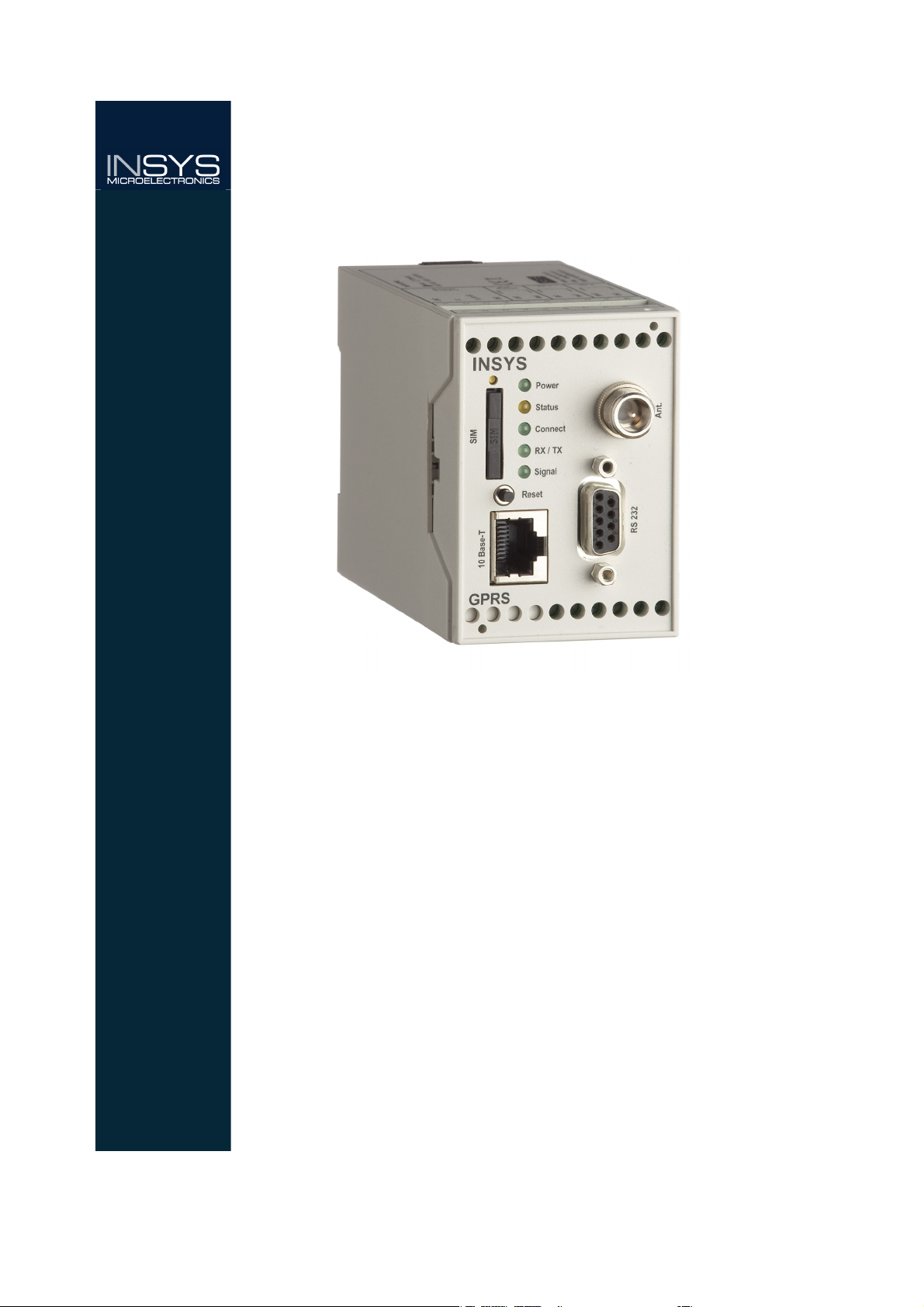
INSYS GPRS 5.0 serial
PC connection cable 9/9-pin (RS232 cable)
User Guide
Please contact your supplier if the content is not complete. Please also check the
modem for shipping damage. Please also refer to your supplier if anything is damaged.
Please keep the packaging material for possible future shipping or storage.
Optional accessories
GSM antenna:
Wall-mounted antenna, magnetic base antenna or patch antenna
CD-ROM with configuration software and manuals
7
Page 8

Function Overview INSYS GPRS 5.0 serial
2 Function Overview
The INSYS GPRS 5.0 serial is a DIN rail device for industrial applications.
It has a compact design, a robust plastic housing and offers the following characteristics:
Quadband GSM engine for all four frequency ranges: 850 / 900 / 1800 / 1900
MHz (The INSYS GPRS 5.0 serial can be used worldwide)
Before using the INSYS GPRS 5.0 serial you should check the certifica-
tion requirements in the country of deployment, see Chapter 14.
Integrated TCP/IP and PPP stack for transparent modem emulation via GRPS
(GRPS modem emulation)
GSM services: GSM/CSD data connection, SMS, GPRS connection
Support for the virtual COM port driver VCOM from INSYS MICROELECTRONICS
GmbH
Integrated TCP/UP stack for modem-compatible behavior with transparent
transfer of data from and to the serial interface (“TCP transparent”).
• Active dialing of IP addresses or domain names with TCP connections to a
server
• Accepts TCP connections ("TCP Listen")
Dedicated line function (leased line); design as CSD or TCP/IP possible; intelli-
gent re-dialing time-outs for TCP/IP cost cutting; configurable substitute access for redundant paths.
Callback function for incoming calls; callback as CSD or “TCP transparent" pos-
sible
Defined termination of GPRS connections for incoming CSD calls ("CSDPRIO")
Access protection via phone number analysis (CLIP) for incoming CSD calls, in-
coming SMS, when starting a callback, and when the priority for CSD calls is
set.
Password protection for remote configuration and configuration via SMS
Storage of the SIM card PIN enables automatic login into the GSM network af-
ter reset/restart
Timer-controlled logout and login into the GSM network or restart of the de-
vice, to prevent undefined login states in the GSM network
Automatic dispatch of a predefined SMS when the switch input is activated.
Advance switch input functionality: Connection setup and "IO tunneling"
(transmitting the input states via a TCP connection)
Standard AT command set according to GSM 07.05 and GSM 07.07
Extended AT command set (INSYS AT command for additional functions)
8
Page 9

INSYS GPRS 5.0 serial Function Overview
Automatic processing of incoming SMS for configuration or connection setup,
also during existing connections
Firmware update of the µ controller (locally and remote)
Integrated SIM reader and external SIM interface for 3V / 1.8 V SIM cards
Hardware watchdog
Extended data formats for the serial interface
Hardware and software handshake at the serial interface
Field strength of the GSM network, status display of the INSYS GPRS 5.0 serial
9
Page 10
Function Overview INSYS GPRS 5.0 serial
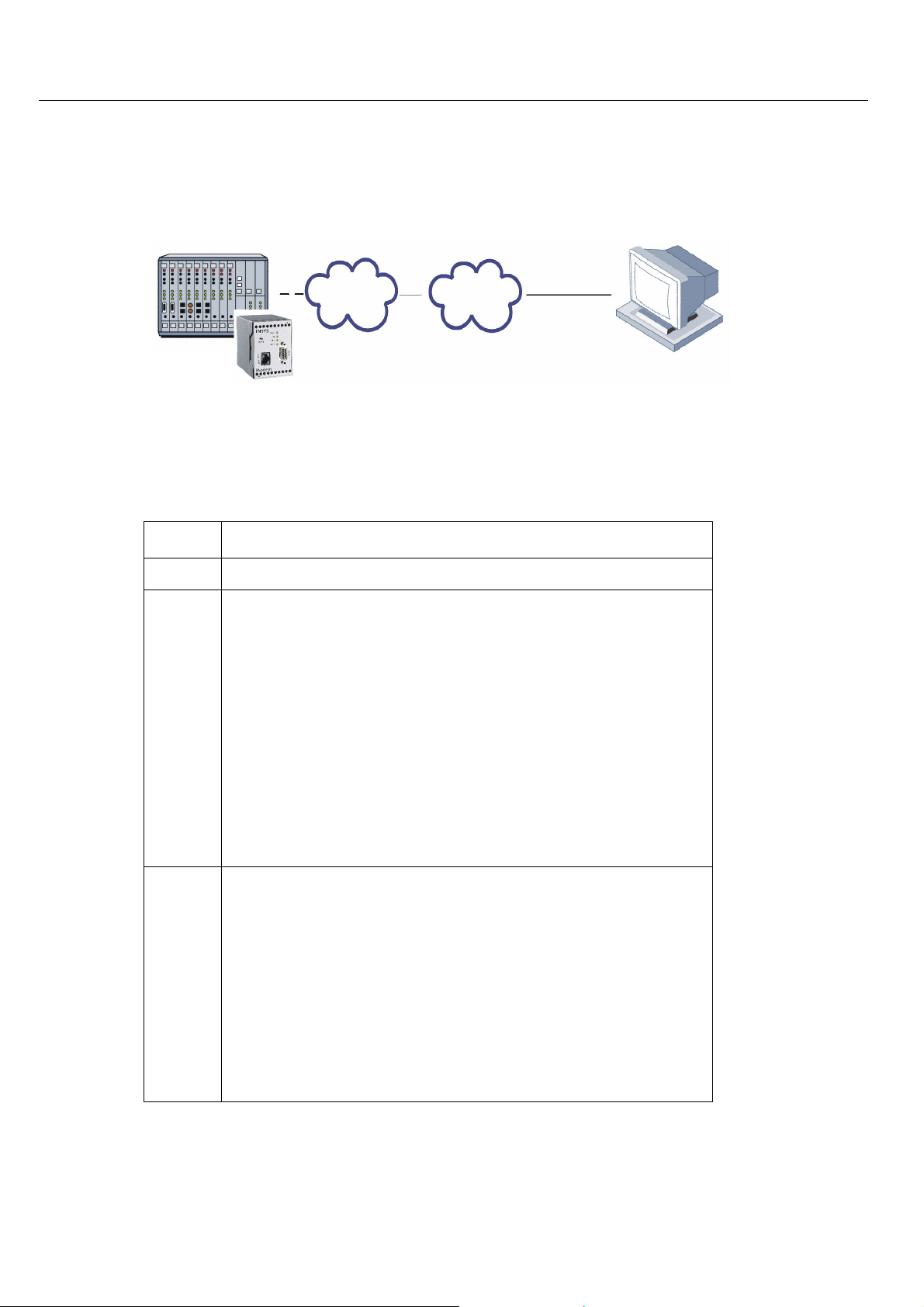
Control center
Internet
GPRS
2.1 Application Example
Controller
GPRS 5.0 serial
2.2 History
Version
2.001
1.00
INSYS
Additional functions
• Redesign
• Further development:
• Accepts incoming TCP connections ("TCP
Listen"), replacement destinations for
AutoDial
• Substitute access for TCP Leased Line
• Termination of GPRS connections for in-
coming CSD calls ("CSDPRIO")
• Software handshake at serial interface
10
• Automatic dispatch of an SMS via switch
input
• Extensions:
• CSDPRIO without CLIP
• IO tunneling via TCP/IP
2.100
• Advanced IO functions: Connection setup
and SMS dispatch triggered via second
switch input
• PPP user name extended to 38 characters
• New baudrate 28800
Page 11

INSYS GPRS 5.0 serial Utilization Notes
3 Utilization Notes
• This manual uses the symbol for especially important notes. Further notes will
be marked accordingly.
• All factory settings are marked “default”.
• In Chapters 4.6 to 7 the description consists of two columns. Individual functions
are described on the left side. The according AT commands and the modem responses can be found in the right column.
Function description AT command
Example:
Dialing IP 192.168.0.2 and port 1234 ATD192.168.0.2:1234
All AT commands start with the letters AT and end with a “Return” (Carriage Return - CR). AT commands can be entered in capital or small letters. The command is
processed after the modem received a CR input.
• In the following, the used syntax is explained:
ATD AT command (font: Courier, bold)
<expression> Input of a parameter
(font: Courier, bold)
[expression] Input of an optional parameter
(font: Courier, bold)
expression Response from the modem
(font: Italic)
Examples:
ATD<ip>:<port> Dialing the IP address <ip>:<port>
ATD192.168.0.1:1234 Dialing the IP address 192.168.0.1 and
the IP port 1234
AT**CALLBACK=0,2,0 The phone number that was stored with
AT**CLIP2 is assigned the action “IP Call-
back”.
AT
+COPS=<n>[,<format>,<oper>]
Select network provider and login
AT+COPS=0 Select network provider automatically and
AT+COPS=4,2,26201 Select network provider (Vodafone) manu ally and lo gin
login
11
Page 12
Mounting INSYS GPRS 5.0 serial
4 Mounting
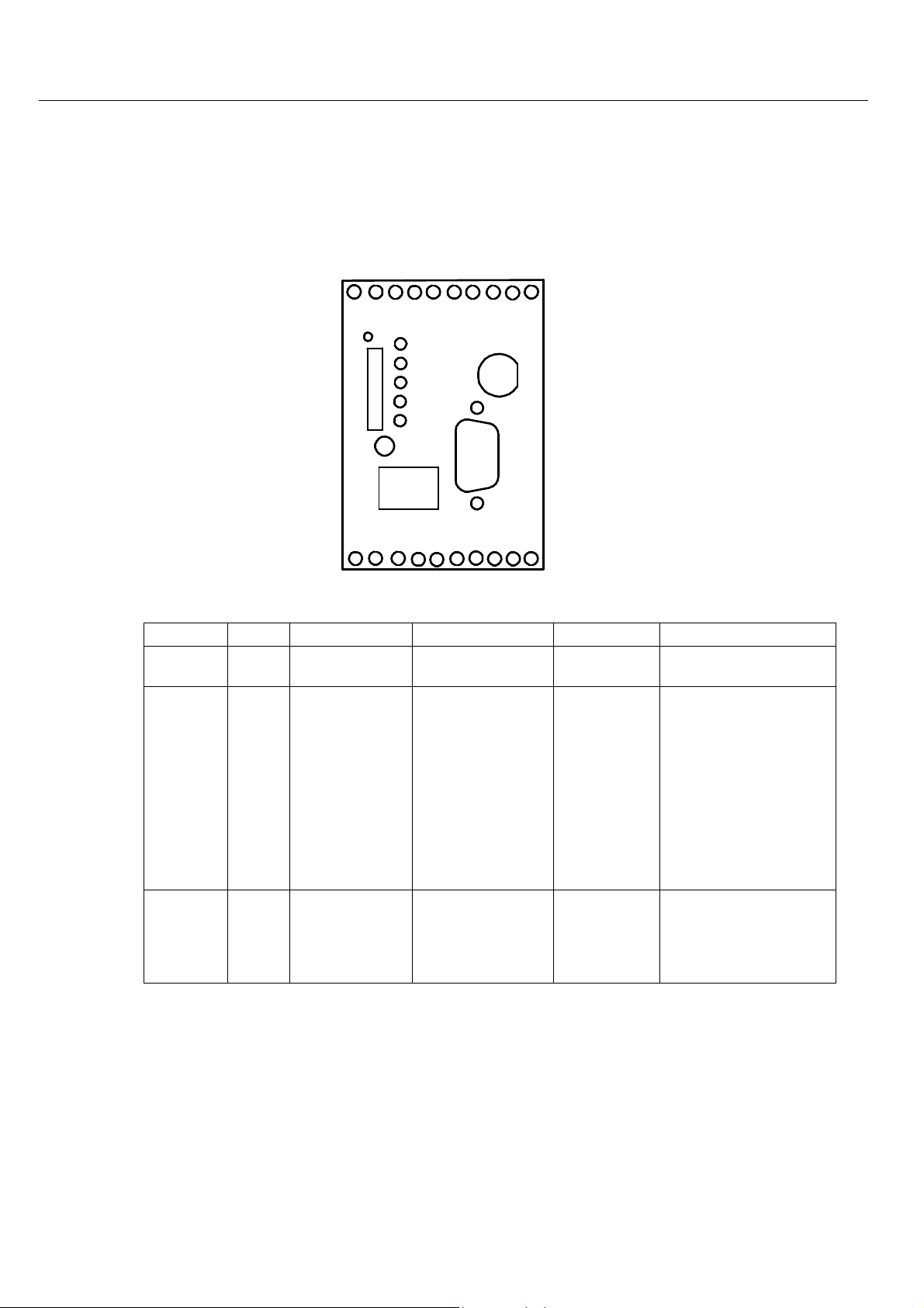
4.1 Front Panel
INSYS
Power
Status
SIM
Connect
RX/TX
Signal
Reset
10 Base-T
Ant.
RS 232
GPRS
The INSYS GPRS 5.0 serial has five LEDs for the operating state:
Name
Color LED off
Power Green
Status Yellow
Connect Yellow
No supply voltage
GSM engine
not logged into
network
No connection
is established
LED on
Supply voltage
available
TCP connection to
the remote terminal has been
established
The connection to
the remote terminal is established (Carrier
detected)
LED blinks
Initialization
phase
LED flashes
Slow flashing (100 ms
on, 1900 ms off): INSYS
GPRS 5.0 serial logged
into the GSM network
Fast flashing (100 ms
on, 900 ms off): PPP
dial-up successful, IP
address received from
provider; in the operating mode "TCP Listen",
this is the normal state
12
Page 13
INSYS GPRS 5.0 serial Mounting
RX/TX
(Receive /
Green
Transmit)
Signal Green
No data exchange
GSM signal
(field strength)
too low
Date is exchanged
via the modem
Best GSM signal
(field strength)
Blinking interval
depending on GSM
signal (field
strength):
ON 25 .. 31
60 ms 23 .. 24
140 ms 21 .. 22
260 ms 19 .. 20
380 ms 17 .. 18
500 ms 15 .. 16
1000 ms 13 .. 14
OFF 0 .. 12, 99
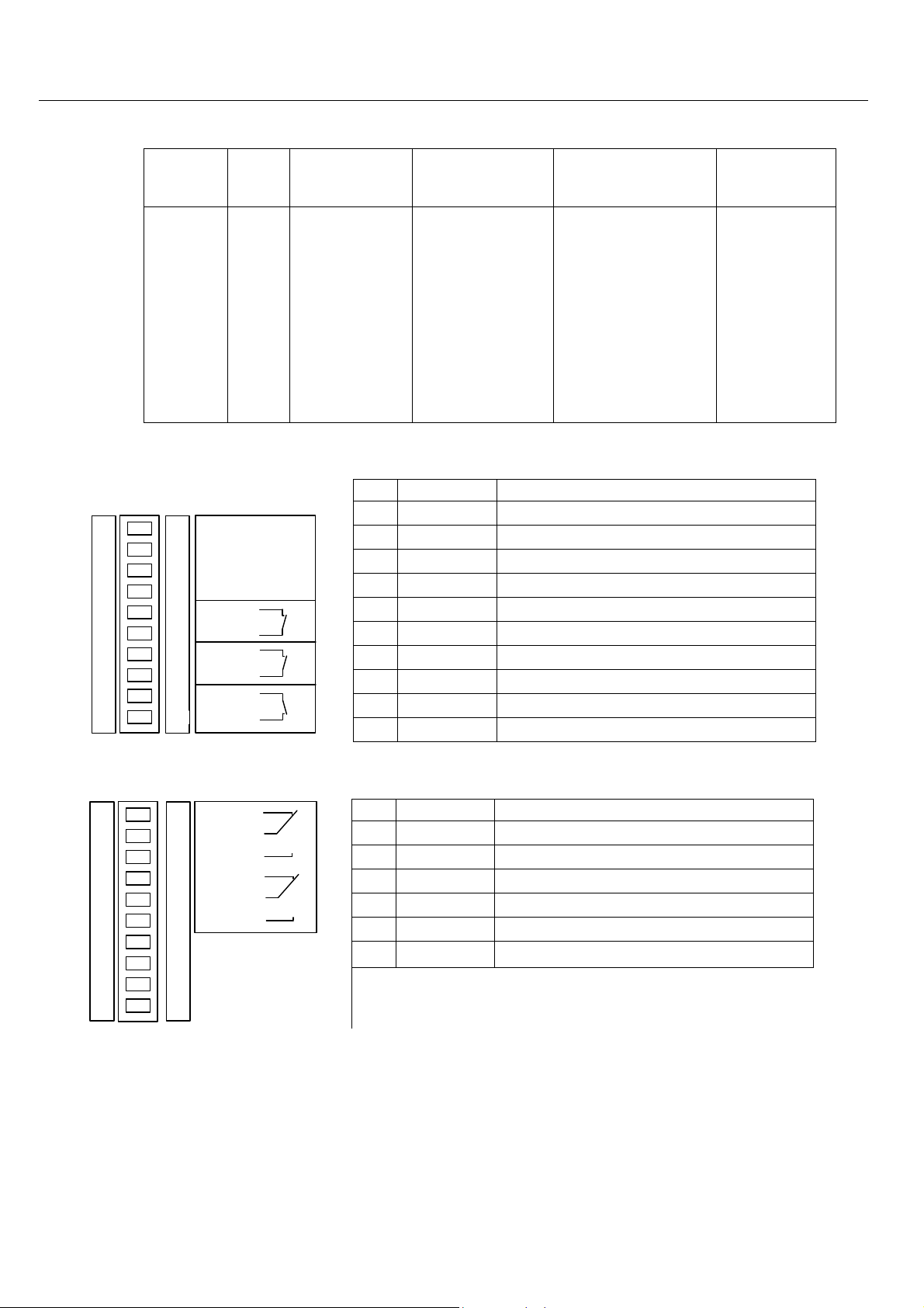
4.2 Top
Terminal
1
2
3
4
5
6
7
8
9
10
1
GND
2
X1
3
10...60 V DC
4
GND
5
GND
6
Reset
7
GND
8
Input 1
9
Input 2
10
GND
supply
Power
Reset
Ext.
IN 1
IN 2
1 GND Ground
2 X1 Reserved
3 10..60V DC Power supply 10V - 60V DC
4 GND Ground
5 GND Ground
6 Reset Reset input
7 GND Ground
8 Input 1 Alarm input 1
9 Input 2 Alarm input 2
10 GND Ground
Meaning
4.3 Bottom
OUT 1-NC
11
12
13
14
15
16
17
18
19
20
11
OUT 1
12
OUT 1-NO
13
OUT 2-NC
14
OUT 2
15
OUT 2-NO
16
17
18
19
20
Terminal
Meaning
11 OUT1-NC Output 1 normally closed
12 OUT1 Output 1
13 OUT1-NO Output 1 normally open
14 OUT2-NC Output 2 normally closed
15 OUT2 Output 2
16 OUT2-NO Output 2 normally open
13
Page 14
Mounting INSYS GPRS 5.0 serial
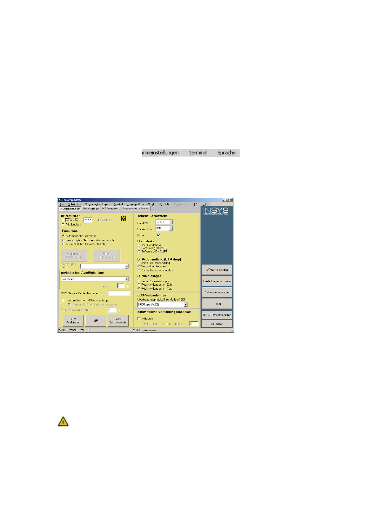
4.4 HSComm GPRS
The configuration of the INSYS GPRS 5.0 serial takes place via AT commands which
are entered by a terminal program or a control program in the form of character
sequences. For a simpler set-up, all basic functions of the INSYS GPRS 5.0 serial can
be entered without knowing the individual AT commands and their parameters,
using the configuration software HSComm GPRS.
The software can be installed on the operating systems Microsoft Windows 2000
and Microsoft Windows XP. A terminal window to enter commands directly is
available.
In Chapter 5 - Connections - and Chapter 6 - Functions -, the HSComm GPRS or another terminal program can be used for the configuration. The AT commands can
be directly entered into the HSComm GPRS at the menu item “Terminal”.
The HSComm GPRS checks the connected device during startup. By default, only
those settings can be selected which are implemented in the identified device.
The buttons in the right column can be used to select the current settings, to restart (reset) the device, or to set the factory settings (default).
The current can be saved as a file at the menu item "File" in the main menu at the
top window border, and reloaded at a later date.
The selected configuration of the parameters is only sent to the INSYS GPRS
5.0 serial after you click on the button Send values.
4.5 Initial Operation
14
Page 15

INSYS GPRS 5.0 serial Mounting
4.5.1 Installation
Caution - Electric shock hazard
This section applies only to the initial startup of the device with factory settings.
1. Have the SIM card and the according PIN ready.
2. Install the device on a DIN rail.
Do not touch live parts when connecting the device.
Make sure that the power supply of the switch board or the system
where the device will be installed is switched off during installation,
and that it is secured against being switched on accidentally.
3. Connect the power supply.
First, connect the ground connection.
4. Connect a suitable power supply (10..60V DC).
Note: The minimum supply voltage value is 10V DC. The maximum supply voltage value is 60V DC.
5. Connect the antenna.
Use a suitable GSM antenna.
You can obtain suitable GSM antennas as accessories for this
device from INSYS.
6. Switch the power supply on.
The power LED will light up.
7. Wait until the device has powered up.
The status LED blinks during the boot process.
The signal LED blinks when the process is completed.
15
Page 16

Mounting INSYS GPRS 5.0 serial
8. Connect the device to the PC.
Connect the 9-pin jack at the device with the serial interface of
your computer.
9. Install the configuration software HSComm GPRS and/or your terminal
program.
10. Start the program HSComm GPRS on the PC.
11. Synchronize the serial interfaces of the PC and the INSYS GPRS 5.0 serial
At delivery, the serial interface settings of the INSYS GPRS 5.0 serial are as follows: 8 data bits, no parity, 1 stop bit, data rate
19,200 Bits/s.
To synchronize the interfaces in the Software HSComm GPRS,
use the button "Synchronize RS232".
For the configuration, the settings of the serial interface of the PC and the
INSYS GPRS 5.0 serial must always be identical!
4.5.2 Driver installation
The installation of a driver is not required when using a terminal program or the
software HSComm GPRS. When using another application, a driver may be necessary. Please find our current drivers at http://www.insys-tec.de/ or install the
standard modem 336 under Windows.
16
Page 17

INSYS GPRS 5.0 serial Mounting
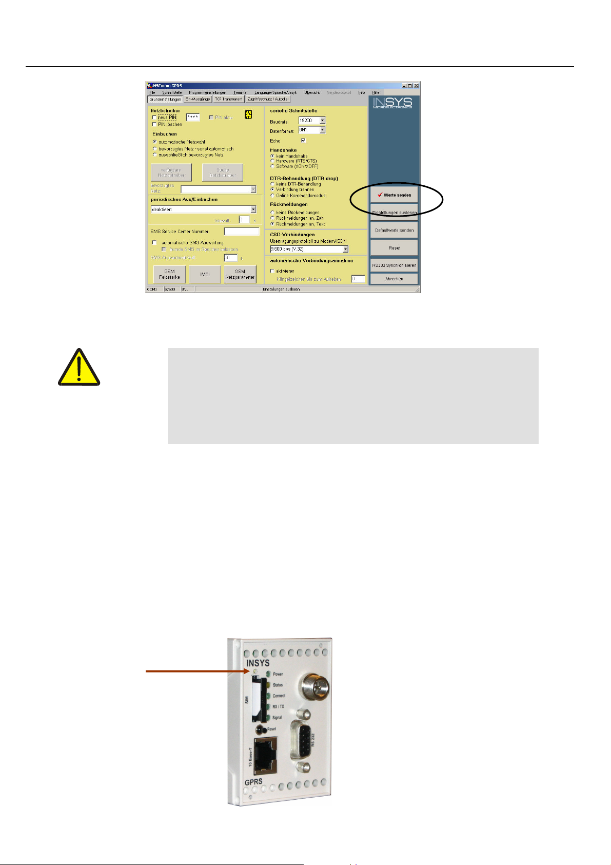
4.5.3 Entering the SIM PIN into the device
1. Start the program HSComm GPRS.
2. Read out the settings.
3. Enter the PIN of the SIM card you are using.
4. Transmit the value to the INSYS GPRS 5.0 serial.
Use the button "Send values".
17
Page 18
Mounting INSYS GPRS 5.0 serial
4.5.4 Insert the SIM card
Caution – Danger of short-circuit for your SIM card!
1. Disconnect the power supply.
2. Remove the SIM card holder.
A short-circuit may occur due to sliding contacts when the card is
removed.
When inserting the SIM card, interrupt the supply voltage to prevent damaging the card when sliding it along the card reader contacts and creating a short-circuit.
The LEDs of the INSYS GPRS 5.0 serial will go out.
Press the sunken button (see image) above the SIM card holder
using a pointed object and remove the card holder.
18
Page 19
INSYS GPRS 5.0 serial Mounting
3. Insert the SIM card into the card holder.
4. Reinsert the SIM card holder into the SIM card reader.
Insert the card holder. The contacts of the SIM card must point
to the left when looking at it from the front of the device.
5. Switch the power supply on.
The device will boot, the power LED will light up continuously, and the
status LED will blink.
6. Wait until the boot process is completed.
The Status LED goes out which indicates that the boot process is completed.
The signal LED is blinking.
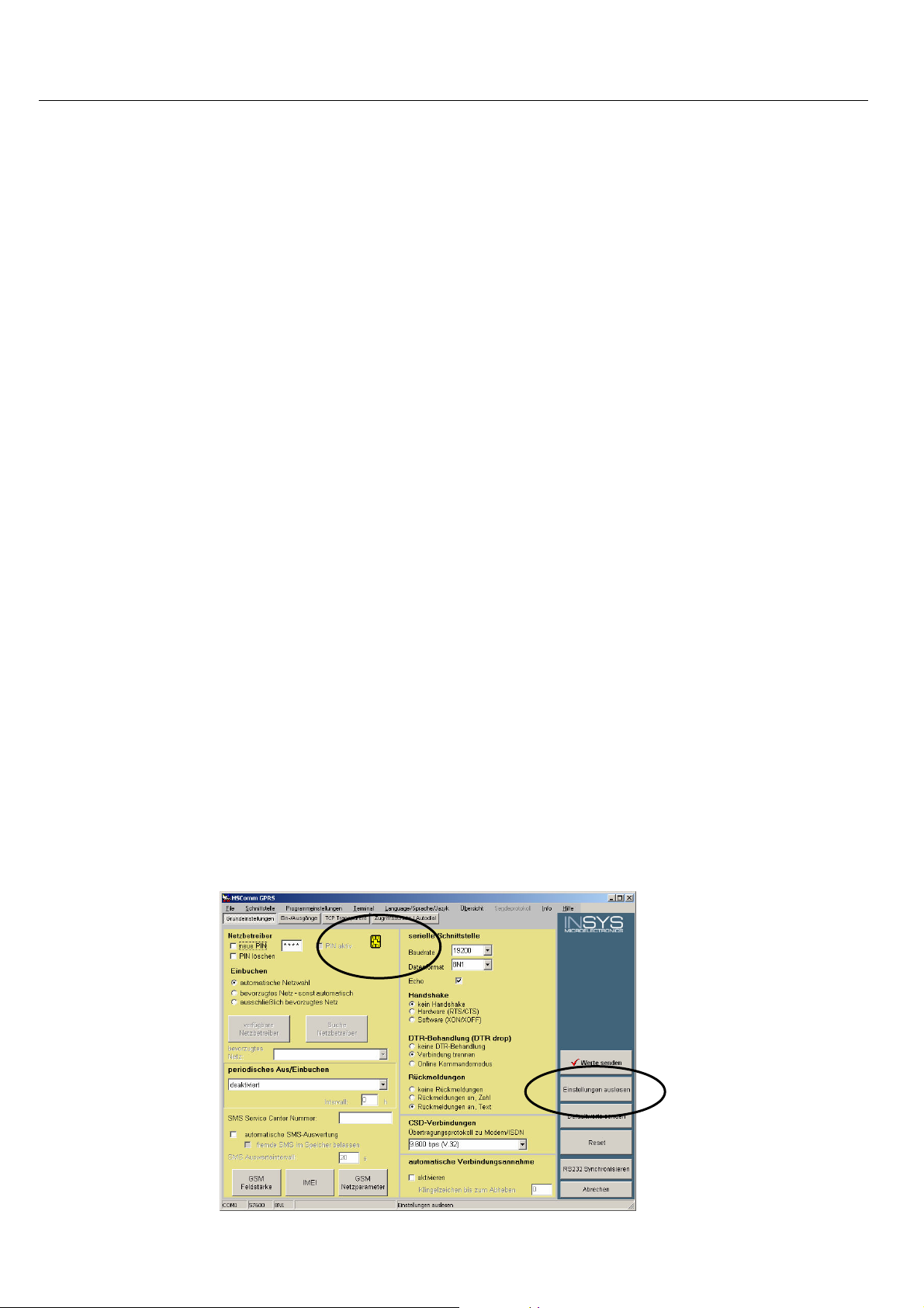
4.5.5 Checking the settings
1. Read out the settings.
Click on the button "Read settings" in the software HSComm
GPRS.
A symbol next the entry field of the PIN will show, if the INSYS GPRS 5.0
serial has been registered.
19
Page 20

Mounting INSYS GPRS 5.0 serial
20
Page 21
INSYS GPRS 5.0 serial Mounting
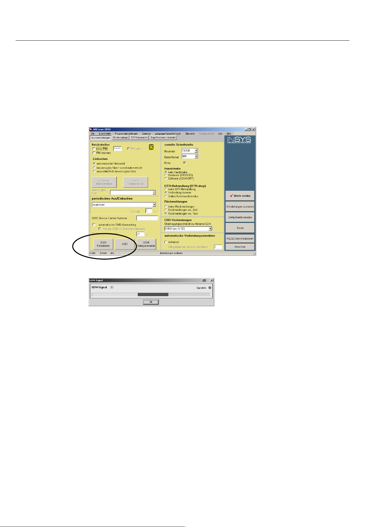
4.5.6 Check the field strength of the GSM signal
2. Read out the GSM field strength.
Use the button "GSM field strength" in the HSComm GPRS.
The field strength is displayed.
The response should be a field strength of at least 12 – otherwise the antenna location needs to be changed to ensure faultless communication.
21
Page 22
Mounting INSYS GPRS 5.0 serial
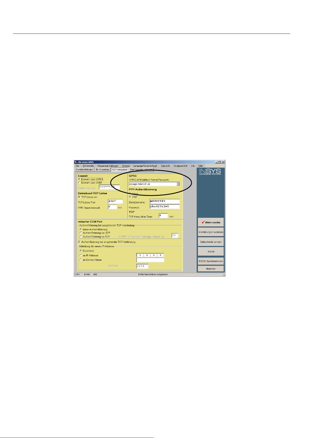
4.5.7 Set GPRS APN (Access Point Name) dial-in parameters
1. Click on the tab "TCP transparent" in the program HSComm GPRS.
see also Chapter 11 - GPRS Dial-in Parameters -
2. Enter the GPRS Access Point Name in the software HSComm GPRS.
Your mobile network provider will inform you about the name
of your APN. Please find an overview of the APNs of some mobile
network providers in the attachment to this manual.
22
For some network providers, PAP authentication is required. See
also Chapter 10: Dial-in parameter.
Page 23

INSYS GPRS 5.0 serial Mounting
If your provider requires PAP authentication, select the required field below the GPRS AN input field and enter the PAP user data.
3. Send the values to the INSYS GPRS 5.0 serial.
Use the button "Send values" in the program HSComm GPRS.
4. Perform a restart.
Use the reset key at the front of the device or disconnect the device from the power supply for a short time.
4.5.8 Establishing a test connection
To establish a test connection to another computer in the Internet, a terminal program
will be required, e.g. TeraTerm. The program is included on the supplied CD, in the folder
software. Alternatively, you may also use other terminal programs. The procedure described in this section, however, applies to the program TeraTerm only. This section will
show how to establish a connection from the INSYS GPRS 5.0 serial to the http server of
INSYS, and how to send the contents of a file.
1. Install the program TeraTerm
2. Start TeraTerm.
3. Configure the serial connection.
During the start phase of TeraTerm, you will be asked to configure a new
connection.
4. Select "Serial" for a connection via a serial interface.
5. Select the serial interface, to which you connected the INSYS GPRS 5.0
serial.
23
Page 24
Mounting INSYS GPRS 5.0 serial
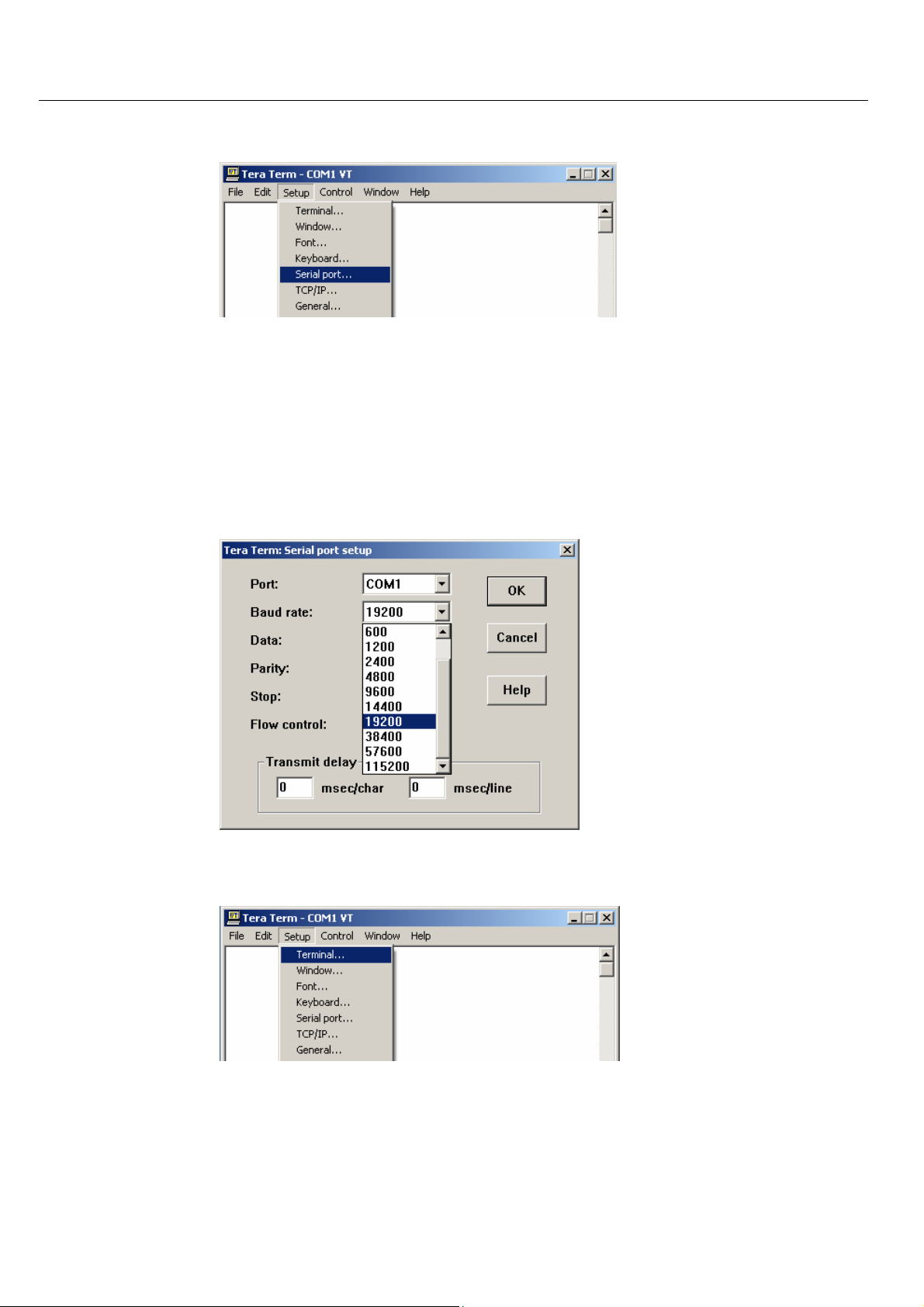
6. Select the item "Serial port" in the TeraTerm menu under "Setup".
7. Set the connection parameters of the serial connection.
As default, the serial interface of the INSYS GPRS 5.0 serial is
configured with the following parameters: Baud rate 19,200, 8
data bits, no parity, 1 stop bit If you did not change these settings in the INSYS GPRS 5.0 serial, use these parameters when
configuring the serial interface of the PC.
24
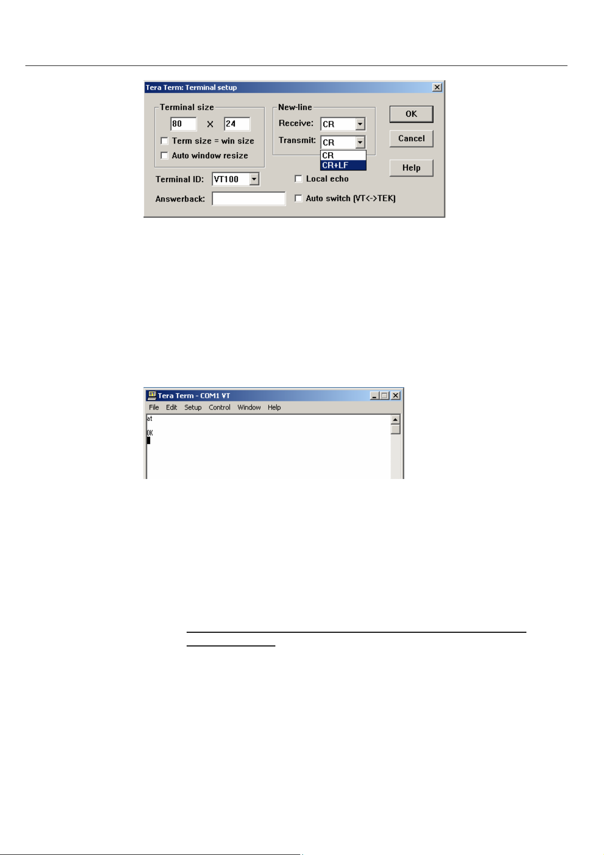
8. Select the item "Terminal" in the TeraTerm menu under "Setup".
9. Configure the terminal behavior.
Page 25
INSYS GPRS 5.0 serial Mounting
10. Test the serial connection to the INSYS GPRS 5.0 serial by entering the
AT command "at" in the terminal window and confirming the entry with
the "Enter" key.
If you don't see the characters at the terminal that you are entering, you most probably selected the wrong baud rate. Repeat
step 6 and 7 to check and correct the connection paramaters.
The INSYS GPRS 5.0 serial will respond with "OK".
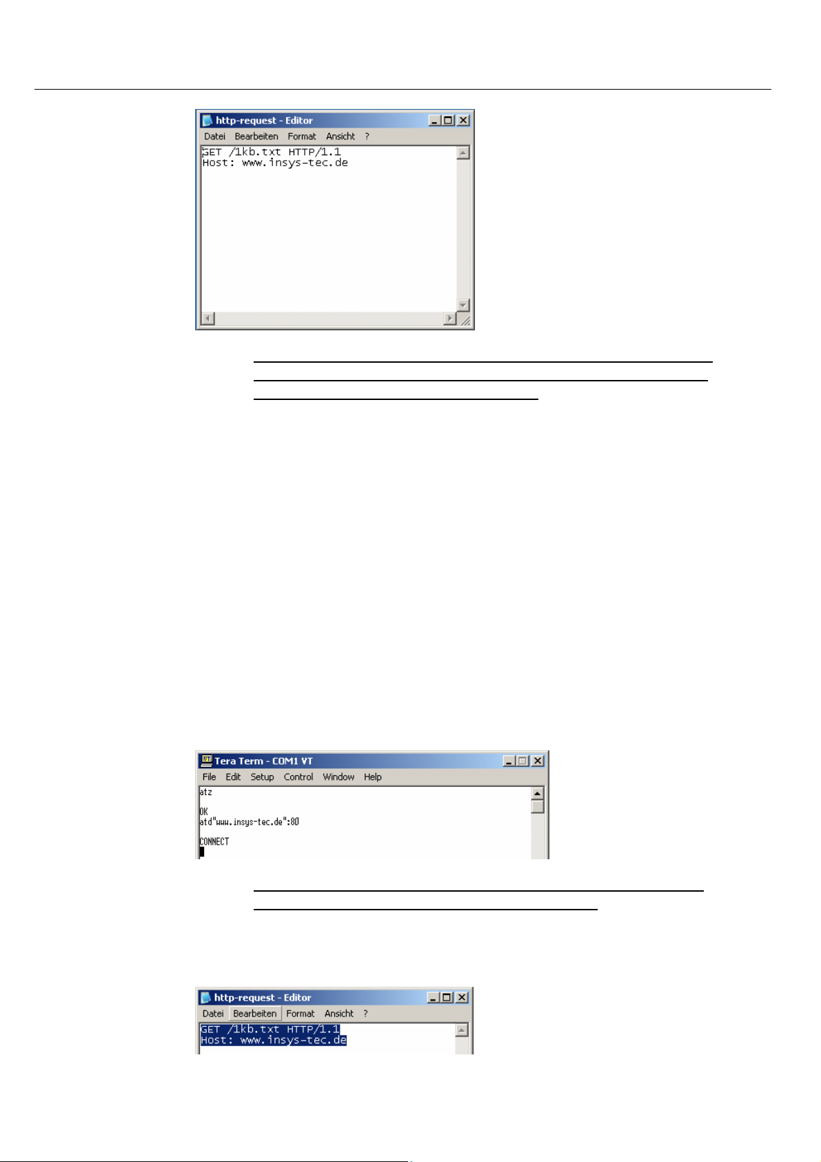
11. Prepare the following commands in a text editor such as "Notepad".
GET /1kb.txt HTTP/1.1
Host: www.insys-tec.de
Please consider case sensitivity.
Complete the entry of each line in the editor by pressing the Enter key one time.
25
Page 26
Mounting INSYS GPRS 5.0 serial
Please note: For the subsequent entries in the terminal window,
you will have a time window of about 20 seconds. Read the last
step before you continue entering data.
12. Enter the following command in the terminal window of TeraTerm:
ATD“www.insys-tec.de“:80
13. Complete the entry by pressing the entry key.
The INSYS GPRS 5.0 serial will now establish a connection to the computer www.insys-tec.de.
The INSYS GPRS 5.0 serial responds with the status message "CONNECT"
in the terminal window, if the connection was established successfully.
The status LED and the connect LED at the device light up.
During an established connection, any further keyboard inputs
are no longer displayed in the terminal window.
14. Mark the commands in the editor and copy them to the clipboard.
26
Page 27
INSYS GPRS 5.0 serial Mounting
Use the key stroke combination "Ctrl+C" to copy the marked text
to the clipboard.
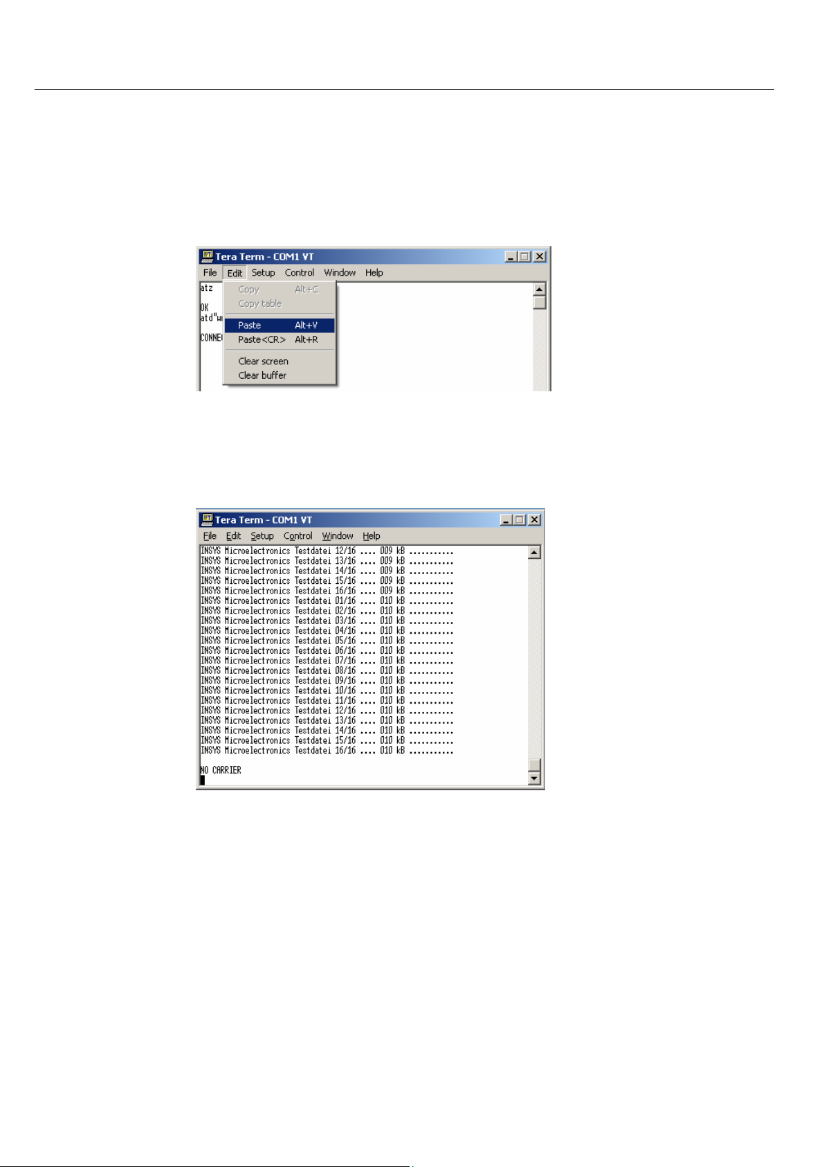
15. Copy the commands to the terminal window and complete your entry
with "Enter".
To insert, use either the key stroke combination "Alt+V" or select the
item "Paste" from the menu "Edit".
After a short waiting period, the contents of the file "1kb.txt" will be displayed in the terminal window.
After another short period the status message "NO CARRIER" will indicate that the remote computer has terminated the connection to the INSYS GPRS 5.0 serial.
27
Page 28
Mounting INSYS GPRS 5.0 serial
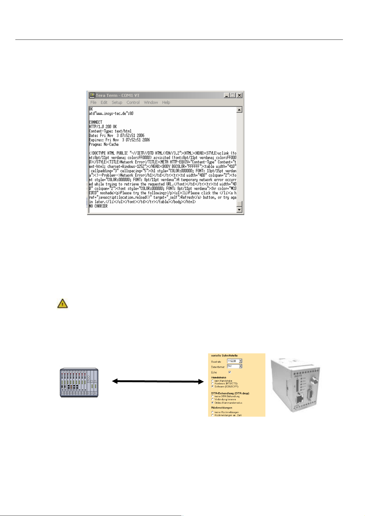
If you cannot see the contents of the file 1kb.txt, but the following message, it has most probably taken you too long to enter it. The http server
has terminated the connection with a timeout. An error message is displayed in HTML code format.
The message includes the HTML code of the side of the server for timeout errors.
To restart an attempt to establish a test connection, start with
step 12.
4.5.9 Connection to the application
For the operation, the application settings and the settings of the INSYS
GPRS 5.0 serial for baud rate, data format and handshake must be identical.
Anwendung {{{PRODUKTBESCHREIBUNG}}}
28
Page 29

INSYS GPRS 5.0 serial Mounting
<1 Sek.
Pause>
4.6 Operating Modes
4.6.1 Command Mode
4.6.1.1 Offline
The offline command mode is the state after the GSM/GPRS
engine was booted and initialized, or after a reset of the
{{{PRODUCT DESCRIPTION}}} . During the offline command
mode the {{{PRODUCT DESCRIPTION}}} can be addressed via AT
commands.
Note
Please note that in the operating mode "TCP List" not all AT commands may be used. See Chapters 5.2.7 and 7.
4.6.1.2 Online
The {{{PRODUCT DESCRIPTION}}} can be switched to online
command mode during a data connection (CSD, GPRS, “TCP
transparent”).
After switching from data mode to online command mode, the
connection will remain established, but no data is transmitted to
the remote terminal. The online command mode is also entered by
DTR drop (setting AT&D1) or by activating the reset input twice
within 10 seconds.
Note: Terminating connections, see Chapters 5.2.9
- Connection termination - and 5.2.9– GPRS Connection termination -
4.6.1.3 Remote
Note: See Chapter 6.8 "Remote Configuration"
4.6.1.4 SMS configuration
Note: See Chapter 6.5 "Automatic SMS Processing"
4.6.2 Connection mode
+++
<1 Sek. Pause>
Depending on the connection type, the data is transformed unaltered
from and to the application (CSD call, GPRS call) or processed by integrated TCP/IP stacks of the µcontroller (TCP transparent).
29
Page 30
Connection INSYS GPRS 5.0 serial
5 Connection
Connection See
Chap.
TCP transparent (modem emulation)
CSD
GPRS direct
(via PPP)
5.3 TCP/IP GPRS
5.3
5.4
Target Bearer Trigger
AT command
GSM
Modem
ISDN
GSM
TCP/IP GPRS
GSM
Incoming con-
nection request
SMS
Callback
Leased Line
Switch input
AT command
SMS
Callback
Leased Line
Incoming call
AT command
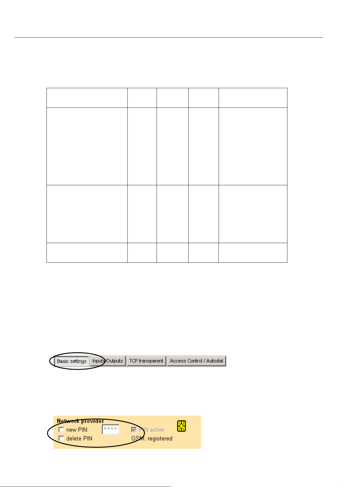
5.1 Logging into the GSM Network
To enable the device to log into the GSM network, the PIN of the SIM card must be
entered in the device.
Click on the tab “Basic Settings”.
Note: see also Chap. 4.5 – Installation -
Automatic login (one-time configuration)
Entering the PIN is only required for new devices or after the SIM card was
switched.
30
Page 31

INSYS GPRS 5.0 serial Connection
Note
As default, the INSYS GPRS 5.0 serial will login to the strongest
available GSM network.
In regions close to borders, registering into the desired network is not always successful. Manually selecting the exclusively preferred network will correct this
problem.
In the first step, the display of all available network providers would be a plus.
Click on the desired network provider in the display. In our example, the available
network provider is T-Mobile – correct description: T-Mobile D
The selected network provider is stored as the preferred network.
31
Page 32

Connection INSYS GPRS 5.0 serial
Transfer the current settings to the INSYS GPRS 5.0 serial. Afterwards, the device
must be reset. After the current settings have been read out, the INSYS GPRS 5.0
serial is registered.
If the device is preconfigured for another country, a search for the desired network provider will be useful.
32
In our example, we search for Vodafone in England (UK).
Page 33

INSYS GPRS 5.0 serial Connection
Mark and then apply the selection.
Alternatively, the settings can be entered or modified using the terminal program.
Enter PIN
If manual network provider selection is
required, the network provider identification number must be determined. You
will find a chart for the INSYS GPRS 5.0
serial with identification numbers and
names in the AT command overview –
available at no charge from INSYS. In
our example, the German network TMobile with the identification number
26201 is used.
Network provider selection for T-Mobile
in Germany
Perform a RESET to use the PIN.
Manual registration after each reset
AT**PIN
AT**PROVIDER=2,1,26201
AT**RESET
If the module is started and logged in from an external application, this application may request a manual login. In this case, the following method should be
used:
Enter the PIN (when the PIN is entered via
AT+CPIN=<PIN>
this command, it must be re-entered for
each reset).
Prompt manual registering (this command
AT+COPS=0
may trigger a waiting period of several seconds)
33
Page 34

Connection INSYS GPRS 5.0 serial
5.2 TCP Transparent (GPRS Modem Emulation)
In this mode, user data is transmitted transparently via the serial interface and in
TCP/IP packets via the GSM/GPRS network. The INSYS GPRS 5.0 serial will act like a
conventional modem at the serial interface.
The remote terminal for this connection type receives the TCP/IP data and evaluates them directly, or has a virtual COM port driver (see Chap. 6.10 - Virtual Com
Port -) to unpack it.
5.2.1.1 Outgoing TCP connections
The INSYS GPRS 5.0 serial will address the remote terminal either directly via the
IP address (e.g. 212.77.161.1) or via the domain name (e.g. www.insys-tec.de).
5.2.1.2 Incoming TCP connections
The INSYS GPRS 5.0 serial is addressed via its IP address. Its IP address must be
routable. The IP address may be static or dynamic. For dynamic IP addresses, the
INSYS GPRS 5.0 serial supports the function to communicate the IP address it received during the dial-up into the GPRS network to a remote terminal (see Chapter VCOM).
The GPRS modem emulation - TCP transparent - can be set with the help of the
HSComm. Click the according tab.
5.2.2 Defaults
For the operation within the GPRS network an APN (Access Point Name) must be
selected.
In HSComm, we prepared numerous European APNs for selection.
34
Page 35

INSYS GPRS 5.0 serial Connection
According to the APN, PPP authentication is required. The necessary information can be obtained from the customer service center of your provider.
When using VPN or "FIX IP" solutions, authentification must in general always be used.
On the basis of the entered APNs you can determine if a user name or a password
is required.
user:<username> or pw:<password>
PAP authentification, user name or password is
required as stated.
user: or pw:
No authentication, user name or password is required.
user:[any] or pw:[any]
PAP authentification, any user name or any password is required.
Alternatively, the settings can be entered or modified using the terminal program.
Enter the Access Point Name (APN)
GPRS dial-in for the integrated TCP/IP stack
AT**GPRSAPN=<apn>
AT**DIALIN=1
GPRS dial-in number for the integrated
AT**DIALINNR=*99***1#
TCP/IP stack
Enter the user name
AT**PPPUSER=<user>
35
Page 36

Connection INSYS GPRS 5.0 serial
Enter the password
Enter the authentification type (usually
AT**PPPPW=<pw>
AT**PPPAUTH=<auth>
PAP)
for the integrated TCP/IP stack
Save settings
AT**SAVE
Perform RESET, accept all parameters
AT**RESET
36
Page 37

INSYS GPRS 5.0 serial Connection
5.2.3 Settings for the leased line
The INSYS GPRS 5.0 serial will automatically establish a leased line after the device
is switched on, or after a reset. The connection is monitored and re-established after interruptions.
For the implementation the selection of the remote terminal – CSD, IP or URL – is
required as a first step. In our example, we selected an IP address as remote terminal.
In a second step, the IP address of the remote terminal must be stated together
with the according port. In our example, this is the IP 192.168.100.1 with port 80.
37
Page 38

Connection INSYS GPRS 5.0 serial
Alternatively, the settings for the leased line operation can be entered or modified using the terminal program.
Connection to an IP address
Setting for leased line function
Remote terminal IP address
Remote terminal TCP port
Save settings
Perform RESET,
AT**LL=2
AT**AUTOIP=<ip>
AT**AUTOPORTIP=<port>
AT**SAVE
AT**RESET
accept all parameters
Connection to a domain name
Setting for leased line function
Remote terminal IP address
Remote terminal TCP port
Save settings
Perform RESET,
AT**LL=3
AT**AUTOURL=<url>
AT**AUTOPORTURL=<port>
AT**SAVE
AT**RESET
accept all parameters
Alternative Access for leased line:
For applications which require high availability even if a remote terminal server
fails, a alternative access may be set.
It is based on the following mechanism:
If the INSYS GPRS 5.0 serial is restarted in leased line operation, the pre-defined
AutoDial default destination is dialed after 20 seconds. If the connection setup
fails, the device will attempt to dial the AutoDial alternative destination. If the
connection setup to the AutoDial alternative destination fails as well or if no
AutoDial alternative destination was entered, the dialing attempt will be repeated
after a waiting period has expired. First the default destination will be attempted
to read, and in case of a failure, the alternative destination. After each failed dialing attempt (this includes both destinations), the waiting period is increased (in
steps of 40, 80, 320, 180 and 3600 seconds). The maximum waiting period is 3600
seconds. After the waiting period has expired, the device will again attempt to establish a connection to one of the two destinations. The command
AT**LLWAITRST defines the maximum number of failures. If this maximum
number of failed connection attempts is reached, the device will be restarted.
Only the failed connection attempts to the main destination are rated. The destination, with which a successful connection is established, will be used as new
AutoDial standard destination until the device is restarted.
38
Page 39

INSYS GPRS 5.0 serial Connection
:
The alternative destination is specified with the following settings:
Connection to an IP address as alternative access
Setting for leased line function
Remote terminal IP address
Remote terminal TCP port
Save settings
Perform RESET,
accept all parameters
Connection to a domain name as alternative access
Setting for leased line function
Remote terminal domain name
Remote terminal TCP port
Save settings
Perform RESET,
accept all parameters
AT**LL2=2
AT**AUTOIP2=<ip>
AT**AUTOPORTIP2=<port>
AT**RESET
AT**SAVE
AT**LL2=3
AT**AUTOURL2=<url>
AT**AUTOPORTIP2=<port>
AT**SAVE
AT**RESET
The successfully established connection is indicated by the control signal DCD and
the message CONNECT.
5.2.4 Settings for TCP Listen (incoming TCP connections)
The function TCP Listen allows the acceptance of incoming TCP connections. The
device will dial into the GPRS network und wait for incoming TCP connections.
Enter the following settings for the operating mode TCP Listen:
39
Page 40

Connection INSYS GPRS 5.0 serial
Alternatively, the settings for TCP Listen can be entered using the terminal program.
Automatic Connection acceptance
Save this setting
ATS0=2
AT&W
Set the TCP data port
Activate TCP Listen
Save settings
Perform RESET,
AT**TCPLISTENPORT=1234
AT**TCPLISTEN=1
AT**SAVE
AT**RESET
accept all parameters
The successful dial-up into the GPRS network is displayed after the startup with
the message +PPP-IP SETUP; the INSYS INSYS GPRS 5.0 serial can now be reached
via its IP address.
If the connection can not be established (network failure, etc.) or if the connection
is terminated, the INSYS GPRS 5.0 serial will automatically start reconnecting.
To limit the connection costs for failed connection setups (for each connection
setup data packets are created and billed), the delay time will increase for every
new repeated attempt.
20 seconds after restart or if the last connection setup was successful
80 seconds after the first failure
320 seconds after the second failure
1280 seconds after the third failure
1 hour for each additional failure
40
Page 41

INSYS GPRS 5.0 serial Connection
For TCP Listen mode, the number of dialing attempts until a device is restarted
can be limited with the command AT**TCPLISTENWAITRST=<n>. For example,
the INSYS GPRS 5.0 serial is restarted with AT**TCPLISTENWAITRST=3 after the
third dialing attempt (20s+80s+320s). This will restart the dialing cycle. The default value for this setting is 255.
5.2.5 Manual connection setup
Establish a connection to an IP address or a host with domain name.
IP address <ip> with port <port>
Domain Name <domain> with the port
<port>
Response: Connect
The call was accepted; the transfer of data can begin.
5.2.6 Automatic connection setup (leased line)
With the leased line function, a preset destination is automatically dialed.
The connection setup and the connection itself are monitored.
If the connection can not be established (network failure, remote system does not
respond) or if the connection is terminated, the INSYS GPRS 5.0 serial will automatically start reconnecting.
To limit the connection costs for inaccessible remote terminals (for each connection setup data packets are created and billed), the delay time will increase for
every new repeated attempt.
ATD<ip>:<port>
ATD<domain>:<port>
20 seconds after restart or if the last connection setup was successful
80 seconds after the first failure
320 seconds after the second failure
1280 seconds after the third failure
1 hour for each additional failure
41
Page 42

Connection INSYS GPRS 5.0 serial
The number of dialing attempts for the leased line mode can be limited with
AT**LLWAITRST=<n>. For example, the INSYS GPRS 5.0 serial is restarted with
AT**LLWAITRST=3 after the third dialing attempt (20s+80s+320s). This will re-
start the dialing cycle. The default value for this setting is 255.
Note
This setting increases the availability of the INSYS GPRS 5.0 serial
and its application. However, due to the increased number of dialing attempts that are performed shortly one after the other, higher
connection costs may occur. This depends on the terms of the contract with the mobile network provider.
5.2.7 Connection acceptance
Use the function TCP listen to accept incoming TCP connections.
Alternatively, the settings can be entered or modified using the terminal program.
Incoming connections are indicated in the
RING
terminal program.
The connection acceptance takes place ei-
ATS0=<n>
ther automatically or after a set number
<n> of ring signals
or manually.:
ATA
The connection was accepted.
CONNECT
As soon as the INSYS GPRS 5.0 serial has displayed the message PPP-IP SETUP, it
can be reached by incoming TCP connections, i.e. it is in Listen mode at the TCP
port which has been set with the command AT**TCPLISTENPORT.
Outgoing TCP connections can still be established.
Please note:
Not all AT commands can be used in the operating mode "TCP Listen".
Please find an overview in the Chapter "7. AT commands".
The INSYS GPRS 5.0 serial is able to independently and periodically check its status
in the GPRS network and thus its availability. Use the command AT**PPPIPCHECK.
42
Page 43

INSYS GPRS 5.0 serial Connection
If the test is successfully performed, the message "+PPP-IP OK" is displayed.
If the test fails, the GPRS connection is terminated (message +PPP-IP RELEASE) and
the TCP Listen mode is reestablished.
To save costs if there is a problem with availability, the waiting time between the
repeat attempts will grow for each subsequent attempt.
20 seconds after restart or if the last connection setup was successful
80 seconds after the first failure
320 seconds after the second failure
1280 seconds after the third failure
1 hour for each additional failure
The number of dialing attempts for the TCP Listen operation can be limited with
AT**TCPLISTENWAITRST=<n>. For example, the INSYS GPRS 5.0 serial is restarted with AT**TCPLISTENWAITRST=3 after the third dialing attempt
(20s+80s+320s). This will restart the dialing cycle. The default value for this setting is 255.
Note
This setting increases the availability of the INSYS GPRS 5.0 serial
and its application. However, the increased number of dialing attempts that are performed shortly one after the other, higher connection costs may occur. This depends on the terms of the contract
with the mobile network provider.
The INSYS GPRS 5.0 serial offers systems with dynamic IP addresses the option to
communicate the IP addresses allocated by the provider during the current GPRS
dial-up into TCP Listen ((+PPP-IP SETUP) to a server. More in Chapter "6.10 Virtual
COM Port".
43
Page 44

Connection INSYS GPRS 5.0 serial
5.2.8 During the connection
5.2.8.1 Keep Alive
The data transfer via GPRS is packet-oriented. If no side of the TCP connection
sends data, there will be no traffic via the transmission link. This also means that
it can not be determined if the remote terminal has disappeared without properly
terminating the connection (e.g. due to a failure of the radio network or a failure
of the remote terminal).
It can also occur that GPRS network providers terminate connections themselves
to be able to offer the resources to other participants, if there is no data transfer
for an extended period of time.
For these cases, TCP offers a suitable accessory by sending Keep Alive messages.
The period between two monitoring packets can be set to 1 minute steps (or be
turned off completely).
If three successive monitoring packets are not responded to, the connection is regarded as terminated, and the INSYS GPRS 5.0 serial returns to offline mode. If the
device is configured as a leased line device, the connection will then be reestablished.
Keep Alive will mostly be used for leased lines, because the application on location
is usually not able to assume the connection control and monitoring.
Alternatively, the settings can be entered or modified using the terminal program.
TCP Keep Alive Timer is set to 10 minutes
Save changes
Changes take effect with a restart of the de-
vice
Note
Keep Alive creates traffic, as each Keep Alive packet is in principle
an empty TCP/IP message which must be confirmed by the remote
terminal. For a Keep Alive, two empty TCP/IP messages with 40 byte
each are sent.
When selection the TCP aggregation timeouts, the rate and the billing type in your GPRS agreement must be considered as well.
See also Chapter 8.8
5.2.8.2 Forming data packets
AT**KEEP=10
AT**SAVE
AT**RESET
44
Page 45

INSYS GPRS 5.0 serial Connection
For a TCP/IP-based transmission such as the
“TCP transparent” connection, the transmitted amount of data consists not only of the
sum of all user data of the application and
the required TCP/IP headers.
Each TCP/IP message has a protocol overhead of 40 bytes. For each message there is
also a confirmation message from the remote terminal with 40 bytes as well.
A selection of parameters, adjusted to the
application, for forming TCP packets in the
integrated TCP/IP stack helps prevent unnecessary high costs for the data transmission.
The INSYS GPRS 5.0 serial sends a data
packet to the remote terminal when:
The maximum set value (default: 512
byte) has been reached
Since the preset waiting time (default:
AT**TCPBLOCK=
<block-size>
AT**TCPAGG=<agg-time>
100 ms) no character has been sent via
the serial interface, and data is already
waiting in the send buffer
(see Chapter 8.8)
5.2.9 Termination
Connections can be terminated as follows:
Manual termination using the ATH command in online command mode
By DTR drop (for the setting AT&D2)
If the remote terminal hangs up
After switching from data mode to online
mode, the connection will remain established. However, data is no longer transmitted to the remote terminal. The online
command mode is also activated by DTR
drop with the setting AT&D1, or by activating the reset input twice within 10 seconds.
The connection was terminated
Data traffic
<1 Sec. Pause>
+++
<1 Sec. Pause>
ATH
Ok
45
Page 46

Connection INSYS GPRS 5.0 serial
5.3 GSM Data Connection (CSD Call)
CSD is the simple modem-like data connection in the GSM network, without using
the GPRS service. Remote terminals for the connection can be analogue modems,
ISDN adapter, or GSM devices.
With the help of HSComm GPRS, the INSYS GPRS 5.0 serial can automatically accept the CSD call. Click on the tab “Basic settings”.
5.3.1 Connection setup
Dial the number to which a connection is to
be set up (always with area code, except for
special provider numbers).
After the call was accepted; the transfer of
data can begin (e.g. connection with 9600
bps). The successfully established connection is indicated by the control signal DCD
and the message CONNECT.
Note
For an active TCP Listen mode, no outgoing CSD connection can be
established.
5.3.2 Incoming connections
ATD<phone number>
Connect 9600/RLP
The connection acceptance takes place either automatically, or after a set number
of ring signals, or manually with ATA.
To accept a call manually with ATA, "0" must be set for "Ring tones until going offhook".
The transmission rate is set for outgoing connections from the device.
For incoming connections to the device, the transmission rate is set automatically
depending on the calling remote terminal.
46
Page 47

INSYS GPRS 5.0 serial Connection
Alternatively, the settings can be entered or modified using the terminal program.
Incoming connections are indicated in the
RING
terminal program.
The connection acceptance takes place ei-
ATS0=<n>
ther automatically, or after a set number
<n> of ring signals, or manually with the
command ATA.
The indicator for incoming connections can in addition display also the connection
type (data, voice) (AT+CRC=1) and the phone number of the caller (AT+CLIP=1)
as an option. Accepting incoming CSD connections for an active TCP Listen mode
is only possible when the function CSDPRIO is used.
Note
In contrast to earlier versions, setting the ring tones until the call
acceptance (S0 registry) with the command ATS0=<n> can only be
performed after a valid PIN was entered.
5.3.3 Termination
Connections can be terminated as follows:
Manual termination using the ATH command in online command mode
By DTR drop (for the setting AT&D2)
If the remote terminal hangs up
After switching from data mode to online
mode, the connection will remain established. However, data is no longer transmitted to the remote terminal. The online
command mode is also entered by DTR drop
(setting AT&D1) or by activating the reset
input twice within 10 seconds.
Hang up (terminate connection to the other
party)
<1 Sec. Pause>
+++
<1 Sec. Pause>
ATH
The connection was terminated
OK
47
Page 48

Connection INSYS GPRS 5.0 serial
5.3.4 Connection to analogue modems
Alternatively, the settings can be entered or modified using the terminal program.
To call an analogue modem, an analogue
protocol must be set. While doing so it must
be observed that the remote terminal has to
work with the same protocol as well.
The protocol V.32 with a data rate of 9600
baud.
5.3.5 Connections to ISDN TAs
Alternatively, the settings can be entered or modified using the terminal program.
To call an ISDN TA it is necessary to set the
ISDN protocol V.110. While doing so it must
be observed that the remote terminal has to
work with the same protocol as well.
AT+CBST=<n>
AT+CBST=7
AT+CBST=<n>
E.g.: The protocol V.110 with a data rate of
9600 baud.
AT+CBST=71
5.4 Direct GPRS Connection via PPP
When the GPRS functionality of the built-in GPRS/GSM Engine of the INSYS GPRS
5.0 serial is used directly, the INSYS GPRS 5.0 serial provides only raw PPP data. In
this case, the application must perform the required protocol stacks (PPP, TCP/IP)
for the application. In this mode, the TCP/IP stack of the INSYS GPRS 5.0 serial is
not active.
Example: Connection via the RDT network of a PC.
The INSYS GPRS 5.0 serial is the PPP server in this mode.
48
Page 49

INSYS GPRS 5.0 serial Connection
The direct utilization of GPR connections via PPP is not possible if the device is in
active TCP Listen mode.
5.4.1 GPRS APN (PDP context)
E.g.: The Vodafone APN address is
WEB.vodafone.DE.
There is basically the option to define several PDP contexts. This one is stored as
context "1".
Note
The PDP context can not be stored permanently; it must be reentered every time the device is restarted,
5.4.2 PPP authentification type
To adjust the authentification type to the one used by the PPP client of the application, the INSYS GPRS 5.0 serial offers two possibilities:
No authentification
PAP authentification
AT+CGDCONT=1,IP,”WEB
.vodafone.DE”
AT^SGAUTH=0
AT^SGAUTH=1
According to the APN, PPP authentication is required. The necessary information
can be obtained from the customer service center of your provider.
5.4.3 GPRS connection setup
Modem-compatible GPRS connection setup
When dialing this special number, the GPRS
service is activated.
If a PDP context (AT+CGDCONT) is defined,
such as: the PDP context no. 1, the AT command will be
The successfully established connection is indicated by the control signal DCD and
the message CONNECT.
After the GPRS connection has been successfully established, the protocol stacks
of the application can start: First the PPP session is started, and then it can be
used for TCP/IP data traffic.
ATD*99***<cid>#
ATD*99***1#
49
Page 50

Connection INSYS GPRS 5.0 serial
5.4.4 GPRS connection termination
Connections can be terminated as follows:
Manual termination using the ATH command in online command mode
By DTR drop (for the setting AT&D2)
After switching from data mode to online
mode, the connection will remain established. However, data is no longer transmitted to the remote terminal. The online
command mode is also entered by DTR drop
(setting AT&D1) or by activating the reset
input twice within 10 seconds.
Hang up (terminate connection to the other
party)
The connection was terminated
+++
ATH
OK
50
Page 51

INSYS GPRS 5.0 serial Functions
6 Functions
6.1 Access Control
Password protection and selective call acceptance can be set using the HSComm. Click on the button "Access Control/Autodial”.
6.1.1 Password protection
The password consists of a maximum of 16 characters and protects
switching into remote configuration during a data connec-
tion (CSD or “TCP transparent”)
accepting SMS for activated, automatic SMS processing.
Click on “Set password” in HSComm.
In the next window, you can setup a new password or change or delete an existing password.
The password is deleted if no new password is entered.
51
Page 52

Functions INSYS GPRS 5.0 serial
Alternatively, a new password can be set or an old password can
be changed or deleted using the terminal program.
Setup new password
Change password
Delete password
6.1.2 Selective call answer
If this function is activated, only connections which originate from
the released phone numbers (1 to 3) are accepted. To use this function, the caller himself has to activate the calling line identification
presentation (CLIP).
The selective call acceptance applies to data and voice connections
as well as incoming SMS commands.
It is furthermore the basic requirement for the callback func-
tion and the function CSDPRIO.
AT**PASSC=<newPW>,<newPW>
AT**PASSC=<old PW>,<newPW>, <newPW>
AT**PASSC=<old PW>
Enter a phone number to activate the selective call acceptance in
HSComm.
52
Page 53

INSYS GPRS 5.0 serial Functions
Alternatively, the access control can be set using the
terminal program:
Activating selective call acceptance
Deactivating selective call acceptance
AT**CLIP=1
AT**CLIP=0
Note: The settings are only changed after they were
saved and the device has been reset.
Incoming calls of numbers which are not allowed are
displayed until the caller ends the signaling. They can
AT**SAVE
AT**RESET
ATA
neither be accepted manually. The caller receives the
signal BUSY.
For each incoming call, the phone number is
displayed as well.
BUSY
RING
+CLIP:
„+49941586920“,1
45,,,,0
The released number has to be configured in exactly the
same format as for a call.
AT**CLIP1=
+49941586920
Note: The transmitted format of the number depends on
the provider – e.g. the leading “+49” may be
replaced by “0049”. We urgently recommend
AT**CLIP1=
+499415869**
verifying the number by placing a test call.
It is possible to allow whole blocks of numbers: The wildcard character „*“ replaces exactly any single digit.
53
Page 54

Functions INSYS GPRS 5.0 serial
6.2 Establishing a Connection by Callback
The callback function enables the INSYS GPRS 5.0 serial to establish a connection
to one of the previously defined remote terminals, when calling from a certain
phone number. The remote terminal can be a phone number, an IP address or a
hostname with domain. The callback is triggered as soon as a call from a previously defined phone number is indicated at the device.
Permitted phone numbers are stored and linked to a destination address (IP address, domain name or phone number) in the configuration.
In connection with the function CSDPRIO (see Chapter 4.3), it is also possible to
trigger a callback if the called INSYS GPRS 5.0 serial has a TCP connection or is dialed into the GPRS network in the operating mode TCP Listen during the call.
The connection setup can be set with a call using the HSComm. Click on the button "Access Control/Autodial”.
The callback function can be activated via the HSComm by entering the phone number and selecting “Callback”.
In the next figure, as an example, the number 1 to trigger the
calling back of a callback number (see AutoDial destinations), the
number 2 of an IP address with port information, and the number 3 of an URL with port information is allocated.
54
Page 55

INSYS GPRS 5.0 serial Functions
See also: see Chapter 5.2.2 - Defaults
Alternatively, the access control can be set using the terminal program:
Default:
For the operation within the GPRS network, an Access Point and
the GPRS access data must be selected.
Activate selective call acceptance
Enter allowed phone number 1
Enter allowed phone number 2
Enter allowed phone number 3
AT**CLIP=1
AT**CLIP1=<nr1>
AT**CLIP2=<nr2>
AT**CLIP3=<nr3>
55
Page 56

Functions INSYS GPRS 5.0 serial
Store possible connection destinations:
IP address and port
Domain name and port
GSM data connection (CSD)
Store the callback connection type (IP, domain
name, CSD) for the three phone numbers
AT**AUTOIP=<ip>
AT**AUTOPORTIP=<port>
AT**AUTOURL=<domain>
AT**AUTOPORTURL=<port>
AT**AUTOCSD=<phone
number>
AT**CALLBACK=
<n1>,<n2>,<n3>
Save settings
AT**SAVE
Perform RESET, accept all parameters
AT**RESET
For IP and domain name destinations it is also possible to enter a
substitute access, it is therefore possible to enter different destinations of the same kind for the different numbers. Example: for
CLIP1 a callback to the IP address 1.2.3.4, and for CLIP2 a callback to
the IP address 5.6.7.8.
56
Page 57

INSYS GPRS 5.0 serial Functions
Example:
A “TCP transparent” connection from the INSYS GPRS
5.0 serial to the service center must be established, controlled by a call (Callback).
In addition, the existing possibility to directly call from
the service center for emergencies (GPRS failure, performance problems) should be maintained. Only the
number of the modem connection for the service center
should be made available for this call.
For a call from the Clip number 2 (mobile phone), a “TCP
transparent” connection to the service center must be
established.
The service center has a normal modem connection
with the number 04989949494. A service mobile phone
with the number 01711253456 exists. Furthermore, the
service center has a fixed internet connection with the
IP address: 200.12.0.120; the TCP port 10000 was enabled for connections to the INSYS GPRS 5.0 serial.
On the tab "Access control/Autodial":
The selective call acceptance/callback must be set in our example
as follows:
57
Page 58

Functions INSYS GPRS 5.0 serial
In a second step, the IP target for the callback must be entered.
Afterwards, on the tab "Basic settings"
the automatic call acceptance after 2 ring tones is required.
Alternatively, our example can be set using the terminal program:
In general, activate selective call acceptance
AT**CLIP=1
Enter allowed phone number 1
Enter allowed phone number 2
Store destination IP for callback
Store destination TCP port for callback
AT**CLIP1=
+494989949494.
AT**CLIP2=
+491711253456
AT**AUTOIP=
200.12.0.120
AT**AUTOPORTIP=
10000
Store callback settings
AT**CALLBACK=
0,2,0
No callback action for call from phone num-
ber 1
IP callback for call from phone number 2
No callback action for call from phone num-
ber 3
58
Page 59

INSYS GPRS 5.0 serial Functions
Save the extended functions
Automatic acceptance of an incoming CSD call
(for the call of a service center modem)
Save setting for ATS0
Perform RESET, accept all parameters
AT**SAVE
ATS0=2
AT&W
AT**RESET
Note
A connection can be established independent from the callback settings via SMS command (provided that the sender number is stored
at AT**CLIP<index>=<n>).
6.3 Defined termination of GPRS connections for incoming
CSD calls ("CSDPRIO")
For different applications, it is necessary to access them with CSD data connections, although the normal operation runs with TCP connections.
The reasons may be as follows:
• To perform time-critical applications (e.g. software updates from controllers).
• To enable service technicians to access the application or the INSYS GPRS 5.0 se-
rial, which are not integrated in the communication system based on TCP connections.
• To still have remote access to the application in case the GPRS network fails.
• To still have remote access to the application in case the TCP infrastructure of the
control center fails.
• The basic requirement for the utilization of CSDPRIO is the support of the selective
call acceptance (AT**CLIP=1). Two modes are available: In the first mode
(AT**CSDPRIO=1), only authorized calls may trigger this function and terminate
the connection. In the second mode (AT**CSDPRIO=2), any caller may terminate
the connection.
• If during the CSD call the following applies:
o A TCP connection is established: It will be terminated (NO CARRIER); some
topics must be observed due to the nature of this:
In some cases (depending on the provider), the TCP RST which the
INSYS GPRS 5.0 serial creates in this case to terminate, the connec-
59
Page 60

Functions INSYS GPRS 5.0 serial
tion will be sent to the remote terminal only after the CSD connection is ended.
If data is transmitted via GPRS during the CSD call (e.g. via a TCP
connection), it may occur that the caller receives the BUSY signal. In
this case, the dial-in should be repeated. The rule of thumb would
be that the CSD call will be forwarded after a minimum of approximately 30 seconds after the last data byte was transmitted via
GPRS.
o A GPRS dial-in (TCP Listen mode, waiting for incoming TCP connection): In
this case, the TCP Listen mode is terminated for the duration of the CSD call
(+PPP-IP RELEASE), and restarted afterwards (+PPP-IP SETUP).
Due to the additional time which is required to terminate the TCP or the GPRS connection, the caller must be prepared for a slightly longer waiting period until the connection
is accepted. Example: If the INSYS GPRS 5.0 serial is set using ATS0=2 for accepting CSD
connections after two ring tones, in general actually 5 to 6 ring tones (RINGs) are required. Please set the number of rings to a minimum of three rings to ensure full functionality, if you want to use automatic call answering.
6.3.1 CSD priority with caller authentification
Alternatively, our example can be set using the terminal program:
In general, activate selective call acceptance
AT**CLIP=1
Enter allowed phone number 1
AT**CLIP1=+49941586920
Activate CSDPRIO
AT**CSDPRIO=1
60
Page 61

INSYS GPRS 5.0 serial Functions
Save settings
AT**SAVE
Perform RESET, accept all parameters
AT**RESET
6.3.2 CSD priority without caller authentification
This function makes it possible that each caller can terminate the existing data connection. In this case, the phone numbers must not be entered. Phone numbers that were
entered anyhow, will not be rated.
Alternatively, the function can be set using the terminal program:
In general, activate selective call acceptance
(To activate the call signals or enable them to
be processed by the INSYS GPRS 5.0 serial,
this setting must be entered.)
Activate CSDPRIO without phone number authentification
Save settings
Perform RESET, accept all parameters
AT**CLIP=1
AT**CSDPRIO=2
AT**SAVE
AT**RESET
Note
Regardless of the authentification settings, a callback number can
be stored.
6.4 Automatic Logout and Login or Restart of the Device
Scheduled logout/login or a device restart can be activated using
the HSComm. Click on the tab “Basic Settings”.
61
Page 62

Functions INSYS GPRS 5.0 serial
6.4.1 Automatic login at restart
The INSYS GPRS 5.0 serial can store the SIM card PIN internally, which enables it to log into the GSM network after
each restart and reset, without user intervention.
All four globally used frequency ranges 850 MHz, 900 MHz,
1800 MHz and 1900 MHz are supported. At the respective location, the INSYS GPRS 5.0 serial will automatically operate
with the frequency range provided by the network provider.
Before using the INSYS GPRS 5.0 serial, you should
check the certification requirements in the country of
deployment.
Note: As default, the INSYS GPRS 5.0 serial will login to
the strongest available GSM network. If required,
a preferred network can be pre-selected with the
command AT**PROVIDER, if necessary.
6.4.2 Periodic Logout and Login or Restart of the Device
AT**PIN=<pin>
AT**PROVIDER=
<mode>[,<form
at>[,<oper>]]
For function support even after infrastructure changes and network software updates by the network providers, the INSYS GPRS
5.0 serial can be logged out of the GSM network via a timer. The
timer can be set by the hour up to a maximum of 99 hours and
starts when the device is switched on. A few minutes after the
module logged out it will automatically log back in. The timer restarts.
If a TCP transparent or a data connection (CSD or GPRS) is established at the time of the logout, the logout will wait until the
connection is terminated.
As an option, there is also the possibility to perform a complete
restart of the device after the timer has expired. The INSYS GPRS
5.0 serial will start automatically with the stored settings.
6.4.2.1 Conditional restart:
If a TCP transparent or a data connection (CSD or GPRS) is established at the time of the logout, the restart will wait until the
connection is terminated.
6.4.2.2 Unconditional restart:
The device is restarted in any case.
62
Page 63

INSYS GPRS 5.0 serial Functions
Examples:
In our example 1, the INSYS GPRS 5.0 serial will be logged out and
back in every 3 hours.
Alternatively, the scheduled logout/login
can be set, changed or deleted using the
terminal program.
AT**LOGOUT=<n>[,<mode>]
Our example – 3 hrs.
AT**LOGOUT=3
In our example 2, the INSYS GPRS 5.0 serial performs a restart
every 3 hours.
Alternatively, the scheduled logout/login
can be set, changed or deleted using the
terminal program.
AT**LOGOUT=<n>[,<mode>]
Our example – 3 hrs.
AT**LOGOUT=3,2
63
Page 64

Functions INSYS GPRS 5.0 serial
6.5 Automatic SMS Processing
Note: The sending time of an SMS from the sender to a re-
cipient depends on the pertinent provider of the
service number. Due to the network load and the
time of day, the time required for sending an SMS
may change.
The automatic processing of SMS messages can be set using the
HSComm. Click on the tab “Basic Settings”.
6.5.1 Activation
Activation in HSComm is done by clicking the automatic SMS
processing.
Each incoming SMS is deleted after it has been processed. Each
SMS with an INSYS AT command is processed. Any other SMS is
immediately deleted.
If other SMS messages are required for processing with the application, the field “Leave remote SMS in SIM buffer” must also be
clicked.
The “remote SMS messages” must be read out regularly.
64
Page 65

INSYS GPRS 5.0 serial Functions
Alternatively, automatic SMS processing can be set, changed or
deleted using the terminal program.
Each incoming SMS is deleted after it has been processed.
AT**SMSRX=1
Only incoming SMS messages with a command to the INSYS
GPRS 5.0 serial are deleted, remote SMS are left in the buffer.
AT**SMSRX=2
6.5.2 Reading interval
The reading interval can be set from 20 to 60 seconds.
Alternatively, the GSM reading interval can be
changed using the terminal program.
AT**GSMREQ=<n>
6.5.3 Syntax
SMS intended for the INSYS GPRS 5.0 serial must have the following syntax:
[<password>,]<command>[,CN: [<callbacknumber>]]
Detailed explanation:
Configuration via SMS, without reply
Note: See also Chapters
and
Configuration via SMS,with acknowledgement:
Note: Between CN: <phonenumber> a space must be
Note
Due to different GSM/GPRS network structures it may occur that
the provider cannot deliver any SMS to the GSM/GPRS engine while
data packets are sent/received via GPRS (this relates to standard
GPRS calls and “TCP transparent” calls via GPRS).
Experience shows that an SMS is only sent during data transmission
breaks longer than 30 seconds.
<command>
Kap.
6.1.1
- Password protection
Kap.
6.1.2
- Selective call answer
<command>,
CN:
[<phonenumber>]
entered. If no phone number is entered after CN:
65
Page 66

Functions INSYS GPRS 5.0 serial
is protected
rotected
the response returns automatically to the sender.
Configuration via SMS, if the INSYS GPRS 5.0 serial
by a password.
Configuration via SMS, if the INSYS GPRS 5.0 serial is p
by a password and a confirmation is desired.
Note: Between CN: <phonenumber> a space must be
entered. If no phone number is entered after CN:
the response returns automatically to the sender.
6.5.4 Access Protection
To protect against unauthorized configuration or attempts to establish a connection, two protection mechanisms are available
which are also used for incoming SMS.
Configuration password
Note: See also Chapter
Selective call answer
Note: See also Chapter
Depending on the settings, SMS from unauthorized senders
or with an invalid password are either
Deleted immediately, or
Stored in the memory and not processed
6.1.1
- Password protection
6.1.2
- Selective call answer
<password>,
<command>
<password>,
<command>,
CN: [<phonenum-
ber>]
AT**PASSC=<pw>
AT**CLIP=1
AT**SMSRX=1
AT**SMSRX=2
6.5.5 SMS storage locations
necessary.
66
The automatic processing of an incoming SMS takes place
via an independent, module-internal interface and has usually no effect on the communication between the application and the GSM/GPRS engine.
Only when the SMS memory is accessed (especially reading
and deleting), it can happen that the µcontroller accesses
the SMS storage location at the same time. In this case, the
application would receive ERROR as response. The application should therefore execute the command once more, if
Page 67

INSYS GPRS 5.0 serial Functions
The INSYS GPRS 5.0 serial evaluates all SMS storage locations made
available by the GSM/GPRS engine (storage locations of the SIM
card and storage locations in the engine itself).
The SMS settings for the module-internal interface used for processing are independent from the interface settings for the application (text mode, used storage locations).
6.6 Manually Dispatching SMS
Note
The sending time of an SMS from the sender to a recipient depends
on the pertinent provider of the service number. Depending on the
network load and the time of day, an SMS may be on the way for an
extended period.
Due to the limited availability of AT commands in the operating mode "TCP Listen", no manual sending of SMS is possible
when the TCP Listen mode is active.
Set SMS text mode
The SMS service center number of the network provider
may be omitted if the number is stored on the SIM card.
Enter the destination phone number
Wait for the prompt “>”, enter the text
The SMS is dispatched using the key combination Ctrl and Z.
Prior to the confirmation message you will be informed
about the amount of SMS that have already been sent.
Note:
The service center phone number must be written in international
format, e.g. for a German provider starting with “+49”.
AT+CMGF=1
AT+CSCA=<nr>
AT+CMGS=<nr>
><text><Ctrl+Z
>
CMGS: <Num>
ok
67
Page 68

Functions INSYS GPRS 5.0 serial
6.7 Digital Inputs and Potential-Free Outputs
The INSYS GPRS 5.0 serial has digital inputs and outputs. The outputs can be switched via
AT commands to control external functions. The inputs can be used to trigger an action
of the INSYS GPRS 5.0 serial. The inputs can be used to dial a connection to an AutoDial
destination or to send an SMS. The action is triggered through a change of the input
from HIGH (inactive) to LOW/GND (active). The level change is accepted after 0.3 seconds, i.e. the input is debounced. In addition, there is the possibility for IO tunneling, i.e.
transmit the input states via a TCP connection to another INSYS GPRS 5.0 serial or a
server.
6.7.1 Automatic SMS dispatch via the switch input
Note
To enable the automatic sending of SMS messages, the device must
know the number of a SMS service center. Make sure that the service center number is entered and stored in the device via AT commands.
The INSYS GPRS 5.0 serial can send a predefined SMS via a level change of the digital inputs UI. The SMS is triggered through the connection of the input with ground (GND).
The alarm input is on HIGH potential by a pull-up resistor in open state (inactive).
The SMS is triggered through a change of the input from HIGH (inactive) to LOW/GND
(active). The level change is accepted after 0.3 seconds (debounce).
To resend the SMS, the input must be set to HIGH (inactive). If the input state at both
inputs changes at the same time, the input state 1 will be evaluated first. If the state
changes at the other input while a state change at one input is being processed, the
event is stored and processed later.
68
Page 69

INSYS GPRS 5.0 serial Functions
69
Page 70

Functions INSYS GPRS 5.0 serial
Alternatively, our example can be set using the terminal program:
In this example, you must note the order of the AT
commands!
AT**INPUT1=1
Automatic activation of SMS dispatch
AT**INPUT1=2
AT**INPUT1=1 for input 1; if you want to use only 1
switch input, use input 1.
AT+CPMS=MT,MT,MT
AT**INPUT2=1 for input 2.
Set SMS storage locations
Activate SMS text mode
AT+CMGF=1
Delete SMS storage location 1 preliminary,
AT+CMGD=2 for storage location 2. You must delete
AT+CMGD=1
AT+CMGD=2
this storage location, if you want to trigger an SMS via
the second input.
The SMS service center number of the network provider
AT+CSCA=<SCNR>
(may be omitted if the number is stored on the SIM card).
Enter the destination phone number
Wait for the prompt “>”, enter the text
AT+CMGW=<nr>
> <text message
1>
The SMS is saved using the key stroke combination
Ctrl+Z.
<Ctrl+Z>
OK
If you trigger an SMS via input 2, you continue entering
the text for the SMS 2.
AT+CMGW=<nr>
> <text message
2>
<Ctrl+Z>
OK
With AT+CMGL=ALL, you can check if the messages were
stored correctly and in the correct order.
70
Page 71

INSYS GPRS 5.0 serial Functions
Save settings for advanced functions
Save settings for SMS commands
Perform RESET, accept all parameters
AT**SAVE
AT&W
AT**RESET
6.7.2 Connection setup via switch input
By changing the input states, connections can be established to the predefined AutoDial
destinations automatically. The inputs are debounced.
At the time of events at the switching inputs, existing connections are terminated. In TCP
Listen mode, the TCP Listener is closed as well. The connection is reestablished after all
the events have been processed, if Leased Line or TCP Listen mode is active.
71
Page 72

Functions INSYS GPRS 5.0 serial
Alternatively, the function can be configured using the terminal program:
Automatic activation of the connection setup for AutoDial destination <n> via input 1.
The command to set the input behavior is
AT**INPUT2=<n> for input 1.
AT**INPUT2=<n> for input 2.
Use the parameter <n> to set the destination, which will
be dialed for an event at the input. Values for <n>:
2: IP connection to AT**AUTOIP/AUTOPORTIP
3: IP connection to AT**AUTOURL/AUTOPORTIP
5: IP connection to AT**AUTOIP2/AUTOPORTIP2
6: IP connection to AT**AUTOURL2/AUTOPORTURL2
Example: Connection to predefined IP via event at input
2:
AT**INPUT1=<n>
AT**INPUT2=2
6.7.3 Transmitting the input states to another INSYS GPRS 5.0 serial (IO
tunneling)
The INSYS GPRS 5.0 serial can transmit its input states to another, remote INSYS GPRS 5.0
serial or to a server via a TCP/IP connection. The second INSYS GPRS 5.0 serial can output
the transmitted states at the outputs. The second device can output the states of its inputs at the outputs of the first device as well. The "Leased Line" function must be active
at the INSYS GPRS 5.0 serial so it can establish a permanent connection to the other INSYS GPRS 5.0 serial. The second device uses the TCP Listen function to accept the connection of the first device. The states are transmitted periodically, i.e. after a set time or
immediately during the change of a state.
The transmission of the states consists of the following sequence:
0x1B<out1><out2>
0x1B = ESC character
<out1>= Value for state 0: 0x30.
Value for state 1: 0x31.
Example =0x1B 0x30 0x31 sets output 1 to 0 and output 2 to 1.
The transmission can take place "in-band", i.e. during a running data transmission. For
this purpose, the Escape character is doubled from the sending INSYS GPRS 5.0 serial.
This means that two Escape characters are sent. This prevents the misinterpretation of
the Escape characters in the data stream.
Configuration of the first device:
72
Page 73

INSYS GPRS 5.0 serial Functions
73
Page 74

Functions INSYS GPRS 5.0 serial
Configuration of the second device:
74
Page 75

INSYS GPRS 5.0 serial Functions
Alternatively, this function can be set using the terminal program:
Configuration of the first device:
Enter the output device as AutoDial address:
AT**LL=2
Activate the leased line operation to the IP address of
the other device
AT**AUTOIP=100.1
20.32.5
Define the transmission port:
AT**AUTOIOPPORT=
1234
Activate the change transmission for input 1:
AT**INPUT1=8
Activate the change transmission for input 2:
AT**INPUT2=8
Set the transmission behavior:
-for the transmission when the level is changed:
AT**INPUTCHANGE=
-for the transmission after a certain time (in minutes):
1
Values for <n>: 1-255 (minutes)
The option AT**INPUTTIMEOUT Option can be used si-
multaneously with AT**INPUTCHANGE.
AT**INPUTTIMEOUT prevents the provider from terminating the unused, open connection.
Save the settings.
Reset the device.
AT**INPUTTIMEOUT
=<n>
AT**SAVE
AT**RESET
Configuration of the second device:
Activate TCP Listen:
AT**TCPLISTEN=1
Set the port to accept the connection
AT**TCPLISTENPOR
T=1234
Activate the automatic connection acceptance after 2
"rings",
ATS0=2
Activate the change transmission for input 1:
AT**INPUT1=8
Activate the change transmission for input 2:
AT**INPUT2=8
Set the transmission behavior:
-for the transmission when the level is changed:
AT**INPUTCHANGE=
1
75
Page 76

Functions INSYS GPRS 5.0 serial
-for the transmission after a certain time (in minutes):
AT**INPUTTIMEOUT
Values for <n>: 1-255 (minutes)
The option AT**INPUTTIMEOUT Option can be used simultaneously with AT**INPUTCHANGE.
AT**INPUTTIMEOUT prevents the provider from terminating the unused, open connection.
Save the settings.
Save the standard settings.
=<n>
AT**SAVE
AT&W
AT**RESET
Reset the device.
6.8 Remote configuration
76
Page 77

INSYS GPRS 5.0 serial Functions
AT**FLASH
During a CSD or “TCP transparent” data connection, the INSYS
GPRS 5.0 serial can be switched to remote command mode by entering the escape sequence via the data connection from the remote terminal.
<pause>
****
<pause>
Note: After the 4 escape characters were entered at the local de-
vice (1 second pause before and after the entry, no return - <CR> -), the remote configuration at the remote
terminal is activated. The data connection is maintained in the background. The 4 escape characters must
be entered within 1 second.
If this was configured, the configuration password is queried before the switching to the remote command mode occurs.
Note: See also Chapter
6.1.1
- Password protection
CONFIG
After the escape sequence is detected, the prompt for entering
the password appears.
PASSWORD:
If no valid password is entered within 30 seconds (attention:
complete the entry with line end character), the configuration
mode will be exited with the following message
A valid password is acknowledged with OK; now the AT commands released for remote configuration can be entered.
Terminate configuration
Note: Due to the sometimes long packet run times for TCP
connections, the escape character **** must be sent in
one TCP packet. Otherwise the pauses between the individual characters get too large and the reception of
the sequence is terminated.
6.9 Firmware Update
The firmware of the µcontroller can be loaded locally (via the serial
interface), and remote (CSD or "TCP transparent" connection).
ERROR
OK
AT**EXIT
Before the firmware is updated, hardware handshake must
always be activated ((INSYS GPRS 5.0 serial and remote terminal).
The process is started. The device prepares itself for receiving the
new firmware.
After the response, the firmware (file with the ending *.hex) is sent
as a text file.
Send *.HEX
file now
77
Page 78

Functions INSYS GPRS 5.0 serial
After the file has been received, the device needs up to 60 seconds
to complete the upload. Afterwards, the (INSYS GPRS 5.0 serial will
automatically perform a restart.)
Note
After an update, the settings for the advanced functions are reset to
the factory defaults.
The SIM card PIN (AT**PIN) and the standard command settings of
the GSM/GPRS engine are maintained, which means that if automatic call acceptance (e.g. ATS0=2) is activated, the device can still
be accessed from outside to enable the re-configuration of the extended functions per CSD call via remote configuration.
6.10 Virtual COM Port
Applications, which up to now communicated with the end devices
via a modem connection or directly via a serial interface, will not
function directly with TCP connections.
A virtual COM port is required, which will process TCP connections
on one side and make a COM port to the operating system available on the other side.
INSYS MICROELECTRONICS GmbH offers a free virtual COM port for the
operating systems Windows XP/2000.
The virtual COM port provides the following functions:
6.10.1.1 Authentication for outgoing TCP connection:
Notification about a unique device ID via a UDP packet prior to the actual
TCP connection, or directly at the beginning of a TCP connection.
6.10.1.2 Information about the new IP address:
78
Page 79

INSYS GPRS 5.0 serial Functions
This setting will only apply to the operating mode TCP Listen. It is used to
communicate the just allocated IP address together with a unique device
ID to the server (IP address or domain name), when IP addresses are dynamically allocated.
6.10.1.3 Authentication for incoming TCP connection:
This setting will only apply to the operating mode TCP Listen. A TCP connection is only accepted if the "caller" has sent a valid authentication via a
UDP packet in advance. This function is also used to terminate a "hanging"
TCP connection for the INSYS GPRS 5.0 serial (e.g. due to a network failure
or a crash of the remote terminal). When a valid UDP packet is received,
the existing TCP connection is terminated to be able to accept the new
connection.
Please request more information about the virtual COM port VCOM from
insys@insys-tec.de.
79
Page 80

Short Description INSYS AT Commands INSYS GPRS 5.0 serial
7 Short Description INSYS AT Commands
7.1 Overview
Command
ATD
ATH
ATA
AT**AUTOCSD
AT**AUTOIP
AT**AUTOPORTIP
AT**AUTOURL
AT**AUTOPORTURL
AT**BAUD
AT**CALLBACK
AT**CLIP
AT**CSDPRIO
AT**DEFAULT
AT**DIALIN
AT**DIALINNR
AT**EXIT
AT**FLASH
AT**FORMAT
AT**GPRSAPN
AT**GSMNET
AT**GSMREQ
AT**IMEI
Implementation possible
Offline local for
Short description
Establish CSD or “TCP
transparent” connections
Terminate CSD or “TCP
transparent” connections
Accept CSD or “TCP
transparent” connections
AutoDial CSD destination number
AutoDial destination: IP
address
AutoDial destination
port for destination IP
AutoDial destination:
domain name
AutoDial destination
port for domain name
Baud rate of the serial
interface
AutoDial function
callback
Selective call answer
Termination of GPRS
connections for incoming CSD calls
Factory settings of the
INSYS AT commands
Dial-in type for integrated TCP/IP stack
Dial-in number for
integrated TCP/IP stack
Exit remote command
mode
Firmware update of the
µcontroller
Data format of the
serial interface
GPRS-APN for integrated TCP/IP stack
Display of GSM network
parameters
Query interval for
automatic SMS processing and reading the
network parameters
Display of device IMEI
Offline
local
X
X
X
X
X
X
X
X
X
X
X
X
X
X
X
X
X
X
X
X
active PPP con-
nection (TCP
Listen)
X
X
X
X
X
X
X
X
X
X
X
X
X
X
X
X
X
X
X
X
X
Online
local
X
X
Remote SMS
X
X
X
X
X
X
X
X
X
X
X
X
X
X
X
X
X
X
X
X
X
X
X
X
X
X
X
X
X
X
X
X
X
X
X
X
X
X
X
X
X
X
X
X
X
X
X
X
X
X
X
X
80
Page 81

INSYS GPRS 5.0 serial Short Description INSYS AT Commands
Command
AT**IMSI
AT**IN
AT**INPUT
AT**INPUTCHANGE
AT**INPUTTIMEOUT
AT**KEEP
AT**LASTCON
AT**LL
AT**LLWAITRST
AT**LOGOUT
AT**OUT
AT**PASSC
AT**PIN
AT**PPPAUTH
AT**PPPPW
AT**PPPUSER
AT**PPPIPCHECK
AT**PROFILE
AT**PROVIDER
AT**RESET
AT**SAVE
AT**SCN
AT**SIGNAL
AT**SMSRX
AT**TCPAGG
AT**TCPBLOCK
AT**TCPLISTEN
Implementation possible
Offline local for
Short description
Display of SIM-IMSI
Query of the switch
inputs
Determine event handling for inputs
Transmitting the input
state for changes at the
input level
Periodic transmission of
the input states
TCP Keep Alive
Display of information
about the last connection
AutoDial function
leased line
Number of failed dialup
attempts until reset in
Leased Line mode
Timer-controlled logout/login
Set/reset the switch
outputs
Configuration password X
SIM card PIN
PPP authentification
type for integrated
TCP/IP stack
PPP password for integrated TCP/IP stack
PPP user name for
integrated TCP/IP stack
PPP connection check
for operating mode TCP
Listen
Display settings
GSM network provider
selection
Restart
Save the extended
INSYS settings
SMS service center
number
GSM signal field
strength
Automatic SMS reception processing
TCP block formation
timer of the integrated
TCP/IP stack:
TCP block size of the
integrated TCP/IP stack
Operating mode TCP
Listen
Offline
local
X
X
X
X
X
X
X
X
X
X
X
X
X
X
X
X
X
X
X
X
X
X
X
X
X
active PPP con-
nection (TCP
Listen)
X
X
X
X
X
X
X
X
X
X
X
X
X
X
X
X
X
X
X
X
X
X
X
X
X
X
X
Online
local
Remote SMS
X
X
X
X
X
X
X
X
X
X
X
X
X
X
X
X
X
X
X
X
X
X
X
X
X
X
X
X
X
X
X
X
X
X
X
X
X
X
X
X
X
X
X
X
X
X
X
X
X
X
X
X
X
X
X
X
X
X
X
X
X
X
X
X
X
X
X
X
X
X
X
X
X
X
X
81
Page 82

Short Description INSYS AT Commands INSYS GPRS 5.0 serial
Command
AT**TCPLISTENPORT
AT**TCPLISTENWAITRST
AT**VCOM
AT**VCOMPORT
AT**VCOMIP
AT**VCOMURL
AT**VCOMTIMEOUT
AT**VERSION
Short description
TCP data port for incoming TCP connections in the operating
mode TCP Listen
Number of failed dialup
attempts until reset in
TCP Listen mode
Support of the INSYS
virtual COM port driver
UDP destination port
for the information
about the IP address for
TCP Listen
UDP destination IP
address for the information about the IP
address for TCP Listen
UDP destination URL for
the information about
the IP address for TCP
Listen
Timeout for TCP variant
for authentification at
the virtual COM port
Display of the software
version
Offline
local
X
X
X
X
X
X
X
X
Implementation possible
Offline local for
active PPP con-
nection (TCP
Listen)
X
X
X
X
X
X
X
X
Online
local
Remote SMS
X
X
X
X
X
X
X
X
X
X
X
X
X
X
X
X
X
X
X
X
X
X
X
X
X = implemented/enabled
82
Page 83

INSYS GPRS 5.0 serial Short Description INSYS AT Commands
7.2 Availability/Storage
The following INSYS AT commands are saved immediately after they are entered
without AT**SAVE, but only activated after a restart.
AT**PROVIDER
AT**PIN
AT**GPRSAPN
AT**PPPAUTH
The following settings are immediately saved when entered, and active:
AT**BAUD
AT**FORMAT
The other settings are immediately accepted and first stored permanently with
AT**SAVE.
83
Page 84

GPRS General INSYS GPRS 5.0 serial
8 GPRS General
8.1 Application Notes
8.1.1 GSM
The provider enables the requested services. A SIM card can be enabled for voice
and data services at the same time. The following table lists the usually available
cards and contracts.
Function Prepaid card Contract for voice
transmission
Outgoing data connection (mobile
originated CSD call)
Incoming data connection (mobile
terminated CSD call)
SMS
Voice connection -
- -
Contract for data
transmission
Contract for voice
and data transmission
(call at data phone
number required)
(call at voice phone
number required)
8.1.2 GPRS
When using data services via GPRS, provider offer various contract options, especially regarding the pricing (basic price, basic data volume, billing unit). Please
contact your provider for further information.
In general, GPRS providers bill every time a connection is terminated and daily at
midnight (the provider will terminate the connection at this time), and all accumulated data are rounded to the billing unit.
We therefore recommend to select a rate which offers the smallest possible billing unit.
Many GSM/GPRS providers offer so-called M2M rates, which have an exact 1 kb
billing matrix.
84
Page 85

INSYS GPRS 5.0 serial GPRS General
Note
The transmitted amounts of data consist of the sum of application
user data and the TCP packet data. The information from the TCP/IP
packets also represents a network load and will add to the total
costs.
For the entire data amount it is also important to select parameters
adjusted to the application to form TCP packets. These parameters
consist of:
The maximum set block value (default: 512 byte) (see
AT**TCPBLOCK)
The maximum waiting period (AT**TCPAGG).
8.2 Network Design
The GPRS system is intended as additional service within the scope of the GSM
system. The GPRS data exchange (GPRS = General Packet Radio Services) runs
packet-oriented, based on the Internet Protocol (IP).
The following figure shows the basic design, where the application has to provide
the TCP/IP/PPP stacks. This is required when using the standard GPRS functionality of the INSYS GPRS 5.0 serial.
Application
Mobile application
TCP
PPP/IP
PPP/IP
IP
GPRS Bearer
GPRS engine
GSM/GPRS
Engine
Router
(GGSN)
IP IP
IP
GPRS Bearer
GPRS Net radio components and internal GPRS net
remote site
application server
TCP
IP
85
Page 86

GPRS General INSYS GPRS 5.0 serial
8.3 TCP Transparent
This function represents the main characteristic of the extended function. By
means of the integrated TCP/IP stacks, the INSYS GPRS 5.0 serial functions as
“modem emulation” for the application; the user data are provided transparently
via the serial interface ("TCP transparent" connection).
There is no need for the application to process any additional protocol stacks.
To establish TCP connections to the INSYS GPRS 5.0 serial, it is necessary to access the
IP address of the GPRS device. This function must be supported by the network operator or the provider.
Application
Mobile application
remote site
TCP
PPP/IP
PPP/IP
IP
GPRS Bearer
INSYS GPRS device
µController
GSM/GPRS
Engine
Router
(GGSN)
IP IP
IP
GPRS Bearer
GPRS Net radio components and internal GPRS net
application server
TCP
IP
Note
The integrated TCP/IP stack will establish a new GPRS connection
for each “TCP transparent” connection, i.e. after the
end/termination of the “TCP transparent” connection follows the
calculation of the GPRS provider, where the data accumulated until
then is rounded to the next billing unit.
This does not apply if the operating mode TCP Listen is activated; in
this case, the GPRS context is preserved after the TCP connection is
terminated, which means that the billing takes place only for a socalled forced billing by the provider (once a day) or during a controlled termination of the GPRS context by the device itself (periodic
login/logout or device restart, termination of the connection and
reconnection due to failed PPPIPCHECK, or deactivation of TCP Listen).
86
Page 87

INSYS GPRS 5.0 serial GPRS General
8.4 IP Addresses/Accessibility
The IP address of the GPRS terminal is dynamically allocated by the provider and
therefore only temporary. During the next dialin at the provider, a new IP address
is allocated.
In almost all GPRS networks the IP address can not be accessed from outside as
the providers perform the addressing for the switch from GPRS networks to the
“normal Internet” via a NAT table (Network Address Translation) to manage the
address area limited by IPV4.
These firewalls prevent the GPRS device or its IP address from being accessed by
so-called "scanners". As GPRS is billed by the amount of data, this prevents unwanted and costly data traffic.
This also means that the following functions may not be possible:
Pinging the GPRS device from outside
Establishing TCP/IP connections to the GPRS device from outside
Sending UDP/IP packets to the GPRS device from outside
All connections (channels) must be opened starting with the GPRS device. This
means that the GPRS device or the application behind it can only react as CLIENT.
Exceptions to this restriction will be provided by the according provider, if available. Please also contact your provider to clarify if it is possible to use a VPN (Virtual Private Network) for possibly required server functionality.
87
Page 88

GPRS General INSYS GPRS 5.0 serial
8.4.1 Fixed IP address and VPN connection
The service provider mdex (http://www.mdex.eu) offers the service "fixed.IP".
With this service, one or more devices in a virtual private network can be addressed. SIM cards are thus grouped to form a closed network with a private IP
address area. Connections from the company network to the devices will then be
established via a VPN tunnel.
The service fixed.IP from mdex will enable GPRS devices to communicate with
each other as well as with computers in the Internet via a VPN connection.
8.5 Data Rates
The INSYS GPRS 5.0 serial has the following characteristics:
GPRS Multislot class 12
GPRS End device class B
Support of coding scheme 1 to 4
PBCCH Support
GPRS has several classes (multislot classes) which are relevant for the transmission speed. The classes provide the maximum transmission speed for uplink and
downlink.
The table below shows the number of time slots for the classes, which can be
used for uplink, downlink, and for the device altogether.
GPRS devices support all variants up to their own Multislot class.
88
Page 89

INSYS GPRS 5.0 serial GPRS General
Multislot class Downlink slots Uplink slots Active slots
8
9
10
11
12
4 TS
3 TS
4 TS
4 TS
4 TS
1 TS
2 TS
2 TS
3 TS
4 TS
5 TS
5 TS
5 TS
5 TS
5 TS
The maximum possible data rate therefore depends on the multislot class of the
device. The above table shows the available time slots (TS) of a device; the table
below shows the maximum data rate. The data rate, on the other hand, depends
on the used coding scheme (CS). This information is unfortunately not available
for the user. The network providers use different coding schemes according to the
reception situation.
1 TS
2 TS
3 TS
4 TS
9,05
18,1
27,15
36,2
53,6
62,4
4 TS
CS1
13,4
26,8
40,2
46,8
3 TS
CS2
15,6
31,2
2 TS
CS3
CS4
Data rates of PC data including GPRS control data
CS1
CS2
CS3
CS4
Data rates of PC data only (without GPRS control data)
21,4 42,8 64,2 85,6
1 TS
8 16 24 32
12 24 36 48
14,4 28,8 43,2 57,6
20 40 60 80
Note: The above mentioned values represent the theoretically maximum possible
values.
In practice, the following applies:
GPRS will not provide guaranteed data rates or bandwidths for the application.
The values allocated by the network provider (coding scheme and time slots to be
used) can change dynamically during a connection and, among other things, depend on the current amount of connections in the GSM cell.
In the device class B, the INSYS GPRS 5.0 serial supports the GSM services GPRS,
CSD and voice. However, only one service can be executed at a time.
89
Page 90

GPRS General INSYS GPRS 5.0 serial
8.6 Quality of Service (QoS)
The above mentioned characteristics data rates (in the form of values such as
“data amount per hour” and maximum data amount) and delay times are, among
others, a part of the Quality of Services.
Theoretically, there is a possibility for requesting a certain QoS profile from the
provider during the connection setup via AT commands (AT+CGQREQ) or to define
a minimum profile (AT+CGQMIN) which must exceeded by the QoS offered by the
provider, in order to enable the device to establish the connection.
Experience has shown that these settings will not show any success regarding
performance improvement, as the providers always supply "Best Effort” as QoS,
i.e. the best values according to the current network load during the moment of
the connection setup.
8.7 Delay Times
Usually, there will be marginally higher delays than with a "normal" connection
via GSM.
The delays will mostly be below one second.
The average delay times are stated with 700 ms, for GSM values of 500 ms are assumed. In rare cases, delays of several seconds are possible; the applications at
the GPRS end devices should therefore be set to maximum delay times.
90
Page 91

INSYS GPRS 5.0 serial GPRS General
8.8 Calculation Examples for Data Transmission via GPRS
8.8.1 Application description
8.8.1.1 Design of the entire system
control center computer
INSYS
vitual
COM-
Port
control center
software
Data logger
RS232
INSYS
GPRS
DEVICE
GSM/GPRS Net Internet
DSL / Modem
The system consists of a data logger with 8 digital inputs and 4 analogue inputs.
The received data can be output in adjustable intervals at the RS232 interface.
The evaluation software at the control center computer will either communicate
directly with the data logger via the RS232 interface, or via leased line modems
for remote applications.
To save investment and maintenance costs (rent, ...) when using leased line modems, the connection should be made via a transparent GPRS modem.
This is what the INSYS GPRS 5.0 serial is used for. It is also used for leased line operation, i.e. after being switched on it will automatically attempt to establish a
connection with the remote terminal, the INSYS virtual COM port. As soon as the
connection is established, all user data from and to the data logger are transmitted via a transparent TCP/IP connection. No adjustment is required for the data
logger and the control center computer.
91
Page 92

GPRS General INSYS GPRS 5.0 serial
Application
T
C
P
/
I
P
A
C
K
:
40
8.8.1.2 Data logger user data
A data logger message has the following setup:
Device ID 4 byte
2 x 8 bit for the digital inputs 2 byte
4 x 16 bit for the analogue inputs 8 byte
Checksum 1 byte
Total 15 byte
8.8.1.3 User data acknowledge of the control center
As an option, the data logger/control center software can be configured so that
for a data logger message an acknowledging message of the control center (user
data acknowledge) is sent.
Set-up:
Command (e.g. ACK) 1 byte
Checksum 1 byte
Total 2 byte
8.8.2 General data amount
For GPRS, such as for all IP-based transmission methods, the user data of the application are packed into a TCP/IP message and sent to the remote terminal
(PUSH); the TCP/IP stack of the remote terminal (e.g. Windows) must acknowledge
each received TCP/IP message.
With GPRS, all data accumulated by the user from the IP level (incoming and outgoing) are calculated.
8.8.2.1 Transmission of user data without user data acknowledge of the remote terminal
/
GPRS modem
control center
92
D
a
t
a:
D
15
P
P
U
S
H
:
4
0
0
a:
t
a
T
C
P
/
I
Total: 95 byte
Page 93

INSYS GPRS 5.0 serial GPRS General
Application
T
C
P
/
I
P
A
C
K
:
40
Application
T
C
P
/
I
P
N
A
C
K
:
4
0
8.8.2.2 Transmission of user data with user data acknowledge of the remote terminal
/
GPRS modem
Total: 177 byte
8.8.2.3 TCP Keep Alive
Some GPRS providers terminate the connections when they are inactive. Vodafone, for example, terminates the connection after approximately 30 minutes
without data transfers. For this reason, applications that exchange data in larger
intervals should consider a Keep Alive timer. The TCP stack generates an empty
TCP message in adjustable intervals which the TCP remote terminal responds to.
This will satisfy the expectations of the provider regarding the amount of data.
The INSYS GPRS 5.0 serial will provide this function.
The application will not notice this action.
control center
D
a
t
a:
D
15
P
P
U
S
H
:
4
0
0
a:
t
a
40
:
K
C
A
P
I
/
2
:
K
C
A
a
t
S
U
P
P
I
D
a
t
a:
0
4
:
H
0
T
C
P
/
I
P
C
T
a
D
/
P
C
T
/
GPRS modem
Total: 80 byte
control center
D
a
t
a:
T
C
P
/
I
P
D
0
P
U
S
H
:
4
0
0
a:
t
a
93
Page 94

GPRS General INSYS GPRS 5.0 serial
8.8.3 Calculation example
We assume a GPRS rate for data with a 1kilobyte billing matrix, as offered by TMobile and Vodafone as M2M rate.
Usually, GPRS network providers bill once daily, e.g. once a day the sum of all accumulated data since the last billing is rounded to the next billing unit (here: 1 kilobyte).
Example T-Mobile: Contract M2M Connect (Date: September 2005)
Basic fee: 3.95 Euro / month
Data extension M2M Data 1 for 1 Mb free volume: 2.95 Euro / month
Data extension M2M Data 2 for 2 Mb free volume: 3.95 Euro / month
Data extension M2M Data 5 for 5 Mb free volume: 4.95 Euro / month
Data extension M2M Data 10 for 10 Mb free volume: 6.95 Euro / month
The following examples show merely the pure data transmission. When a TCP/IP
connection is established via the INSYS GPRS 5.0 serial, data is also generated
(128 byte). The INSYS GPRS 5.0 serial will not terminate a once established connection automatically, i.e. the amount of data for the connection setup may be ignored.
However, the following may occur:
The remote terminal can no longer be reached (power failure in the control
center, system crash, new IP address for the control center, …)
The GSM/GPRS network breaks down temporarily
The GPRS modem has a power cut
In all cases, the INSYS GPRS 5.0 serial will automatically attempt a new connection
setup to guarantee the availability of the application (attempts in intervals of 20s,
80s, 320, 1280s, 1h, 1h, 1h, …).
For the M2M rates, for each (failed) connection setup attempt 1kilobyte amount
of data may be assumed (at a 1 kilobyte matrix); it is therefore recommended to
plan a reserve of 30 to 50 kb up to the according upper limit of the rate.
94
Page 95

INSYS GPRS 5.0 serial GPRS General
Transmission of values every 15 minutes
Without user data acknowledge
95 byte / 15 min 380 byte / 1 h 9120 byte / 24 h rounded to 9 kb / day
270 kb / month
The contract M2M Connect with M2M Data 1 is sufficient; at all events, there
is enough reserve available.
The monthly costs would be 3.95 + 2.95 = 6.90 Euro.
With user data acknowledge
177 byte / 15 min 708 byte / 1 h 16992 byte / 24 h rounded to 17 kb /
day 510 kb / month
The contract M2M Connect with M2M Data 1 is sufficient; at all events, there
is enough reserve available.
The monthly costs would be 3.95 + 2.95 = 6.90 Euro.
95
Page 96

Sending SMS as Fax or E-mail INSYS GPRS 5.0 serial
9 Sending SMS as Fax or E-mail
Overview of network providers for German speaking countries (D, A, CH). All necessary information is available from the customer service center of the provider.
(Subject to change)
9.1 SMS as Fax
Network Provider
T-Mobile (D1)
D2 Vodafone
E-Plus (E1)
T-Mobile
Swisscom
Swisscom
Coun
Service center
try
D +49 171 076 0000
D +49 172 227 0333
D +49 177 061 0000
A
CH +41 79 499 9000
CH +41 79 499 8123
9.2 SMS as E-Mail
Network Provider
T-Mobile (D1) D
Coun
try
Service center
+49 171 076 0000 8000
Phone
number
99 + dialing code
+ Phone number
99 + dialing code
+ Phone number
151 + dialing
code
+ Phone number
6762 + dialing
code
+ Phone number
Dialing code
+ Phone number
Dialing code
+ Phone number
Phone
number
SMS format
Example
990941586920 This is a test
990941586920 This is a test
1510941586920 This is a test
67620941586920 This is a test
0941586920 *FAX#This is a test
0941586920 *FAX#This is a test
Format
E-mail address Example
D2 Vodafone D
E-Plus (E1)
T-Mobile A +43 676 021 6761
Swisscom CH +41 79 499 9000 555
Swisscom CH +41 79 499 8123 555
+49 172 227 0333 3400
D
+49 177 061 0000 7676245
96
E-mail address
+ space
+ text
abc@defg.de
abc*defg.de
This is a
test
Page 97

INSYS GPRS 5.0 serial GPRS Dial-in Parameters
10 GPRS Dial-in Parameters
Overview of network providers for German speaking countries (D, A, CH). All necessary information is available from the customer service center of the provider.
Note: In HSComm we prepared numerous European APNs for selection.
(See also Chapter 5.2 - TCP Transparent (GPRS Modem Emulation))
Network Provider
T-Mobile (D1)
Germany
D2 Vodafone
Germany
E-Plus (E1)
Germany
O2 (E2)
Germany
T-Mobile
Austria
Swisscom
Switzerland
mdex
*) not required.
**) any password required
APN
AT**GSMAPN=<apn>
internet.t-d1.de
Internet.t-mobile.de
web.vodafone.de
internet.eplus.de
surf.xxl.interkom.de
netcompany.interkom.de
gprsinternet
gprs.swisscom.ch
voyager.tda.t-d1.de
User name
AT**PPPUSER=<user>
*) *)
Password
AT**PPPPW=<pw>
See contract data
**) **)
eplus
*) *)
GPRS
gprs
See contract data
gprs
*)
Gprs
97
Page 98

FAQ INSYS GPRS 5.0 serial
11 FAQ
Problem: Possible cause: Remedy
The INSYS GPRS 5.0 serial
does not log in:
No reaction to AT commands.
The location of the GSM
antenna is incorrect.
PIN incorrect Use the HSComm to delete the PIN and to
The SIM card is blocked
because the PIN was entered incorrectly three
times.
The SIM card is not enabled.
The power supply is not
sufficient.
The wrong interface has
been selected in the settings for the serial interface.
There is another program
running in the background
which accesses the same
serial interface.
Check the signal quality of the GSM network. For low field strength – below 12 –
the antenna location should be changed.
enter the correct PIN.
A PUK must be entered to enable the card.
Switch to the terminal program to enter
the PUK
and enter the following command:
AT+CPIN=<PUK>,<new PIN>
Please contact the contact center of your
provider.
Check the voltage supply using the information from Chapter 12 – Technical
Data.
Check the interface settings
with the used COM port.
Terminate all programs running in the
background.
98
Page 99

INSYS GPRS 5.0 serial FAQ
Problem: Possible cause: Remedy
No reaction to AT commands.
The serial interface settings
at INSYS GPRS 5.0 serial and
at the application are not
identical.
The INSYS GPRS 5.0 serial and the application (configuration PC or controller) must
be operated at the serial interface with
the same settings for baud rate and data
format.
Check the settings of both interfaces!
Settings INSYS GPRS 5.0 serial:
Setting of the application - in our example a PC with the HSComm GPRS:
99
Page 100

FAQ INSYS GPRS 5.0 serial
No Dialtone
Problem: Possible cause: Remedy
The manual selection of
ATD<ip>:<port> or
ATD<domain>:<port>
is not possible. After a few
seconds, the messages No
Carrier or
are displayed.
The GPRS dial-in parameters have not been set correctly.
Step 1:
Read out all data using the button “Read
settings” from the device and check the
settings.
Step 2:
On the tab "TCP transparent" check the
selection of the network provider.
For some network providers, PAP authentication is required.
Please find a selection of network providers for German speaking countries (Germany, Austria, Switzerland) in Chapter 11
“GPS Dial-in Parameters” or ask the customer center of your provider for the correct settings.
Step 3:
Change the settings, if necessary and
restart the INSYS GPRS 5.0 serial.
Step 4:
Switch to the terminal program
and manually dial into the GPRS network.
Enter the AT command ATD*99***1#.
The successful connection setup is confirmed with the message Connect.
100
 Loading...