

Page 1
G-force meter
UTC and local time display
Slip indicator
Battery Voltage, *Current and Charge display
OAT display
Flight Timer & Flight log
Stopwatch
Countdown Timer
Alarm
* Requires the MGL Avionics magnetic field or active current shunt (sold separately)
Vega INFO-1
Information Display
Operating Manual – English 1.01
Page 2

Vega INFO-1 Operating Manual Page 2
Introduction
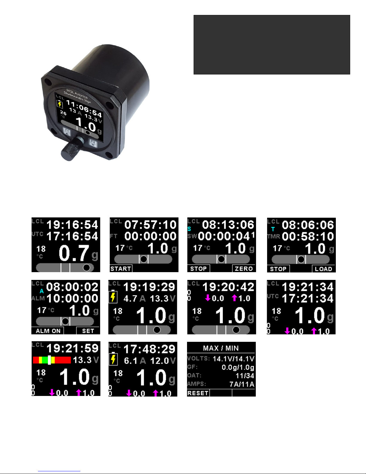
The INFO-1 is a 2 1/4” sunlight readable multifunction color display instrument. The INFO-1 has the following features:
G-force meter
The INFO-1 is capable of measuring g-forces exerted in an aircraft up to +-16g. The INFO-1 also has the facility to record
the maximum positive and negative g-forces encountered (typically during a flight) in permanent memory, with a
password protected reset facility. It also features two independent cycle counters to capture the amount of times a preset
force has been exceeded. The INFO-1 is able to measure g-forces even if the instrument is not mounted exactly on the
vertical axis of the aircraft.
UTC and Local Time display
The INFO-1 is capable of displaying both UTC (as known as Zulu time) and local time to facilitate ordinary ATC time
reporting. Time is maintained by an internal lithium battery which can be replaced by the user.
Slip indicator
The INFO-1 can display a slip indicator. The slip indicator can be disabled in the menu system.
Battery Voltage, *Current and Charge display
The INFO-1 can be used to monitor your aircraft’s battery power supply. The INFO-1 is very useful in determining your
battery’s health, charging status, as well as the current load consumption of your aircraft. The INFO-1 can be used in both
12V and 24V aircraft and can measure voltages up to 30V DC.
The INFO-1 uses the MGL Avionics magnetic field or active current shunt to measure the aircrafts current load. The
INFO-1 contains a programmable low/high voltage alarm to automatically detect bad batteries and alternator failures. The
maximum and minimum voltage reached is also recorded in permanent memory.
OAT display
OAT can be shown in either degrees Celsius or degrees Fahrenheit. The INFO-1 also contains a programmable low/high
OAT alarm. The maximum and minimum OAT reached is also recorded in permanent memory.
Flight Timer & Flight log
The INFO-1 provides a 50 entry flight log that stores the start time and duration of each of the last 50 flights. The flight
timer can either be started using a front push button or from a remote input.
Stopwatch, Countdown Timer & Alarm
Stopwatch and timers can be operated simultaneously to a programmable alarm, making the INFO-1 particularly suitable
for sport flying competitions.
1 Features
• 1.8” high resolution 160x128, sunlight readable, wide viewing angle, 1000 cd/m2 TFT LCD display
• G-force range of +-16g
• Records the maximum positive and negative g-forces encountered (typically during a flight) in permanent
memory, with a password protected reset facility
• Two independent cycle counters capture the amount of times a preset force has been exceeded
• Able to measure G-forces even if the instrument is not mounted exactly on the vertical axis of the aircraft
• Capable of displaying both UTC (Zulu time) and local time
• Time is maintained by an internal lithium battery which can be replaced by the user
• Can measure voltages up to 30V (compatible with both 12V and 24V aircraft supplies)
• Contains a programmable low/high voltage alarm to automatically detect alternator failures and bad
batteries
• Uses the MGL Avionics magnetic field or active current shunt to measure the aircrafts current load.
• *Contains a charge status indicator
• OAT can be shown in degrees Celsius or degrees Fahrenheit
• Contains a programmable low/high OAT alarm
• Provides a 50 entry flight log that stores the start time and duration of each of the last 50 flights
Page 3
Vega INFO-1 Operating Manual Page 3
• The flight timer can either be started using a front push button or from a remote input
• Stopwatch and timers can operate simultaneously to a programmable alarm
• Standard 2 1/4” aircraft enclosure (can be front or rear mounted)
• Rotary control plus 2 independent buttons for easy menu navigation and user input
• An external output activates when an alarm condition has been reached
• Wide input supply voltage range of 8 to 30V DC with built in voltage reversal and over voltage protection
for harsh electrical environments
• 1 year limited warranty
* Requires the MGL Avionics magnetic field or active current shunt (sold separately)
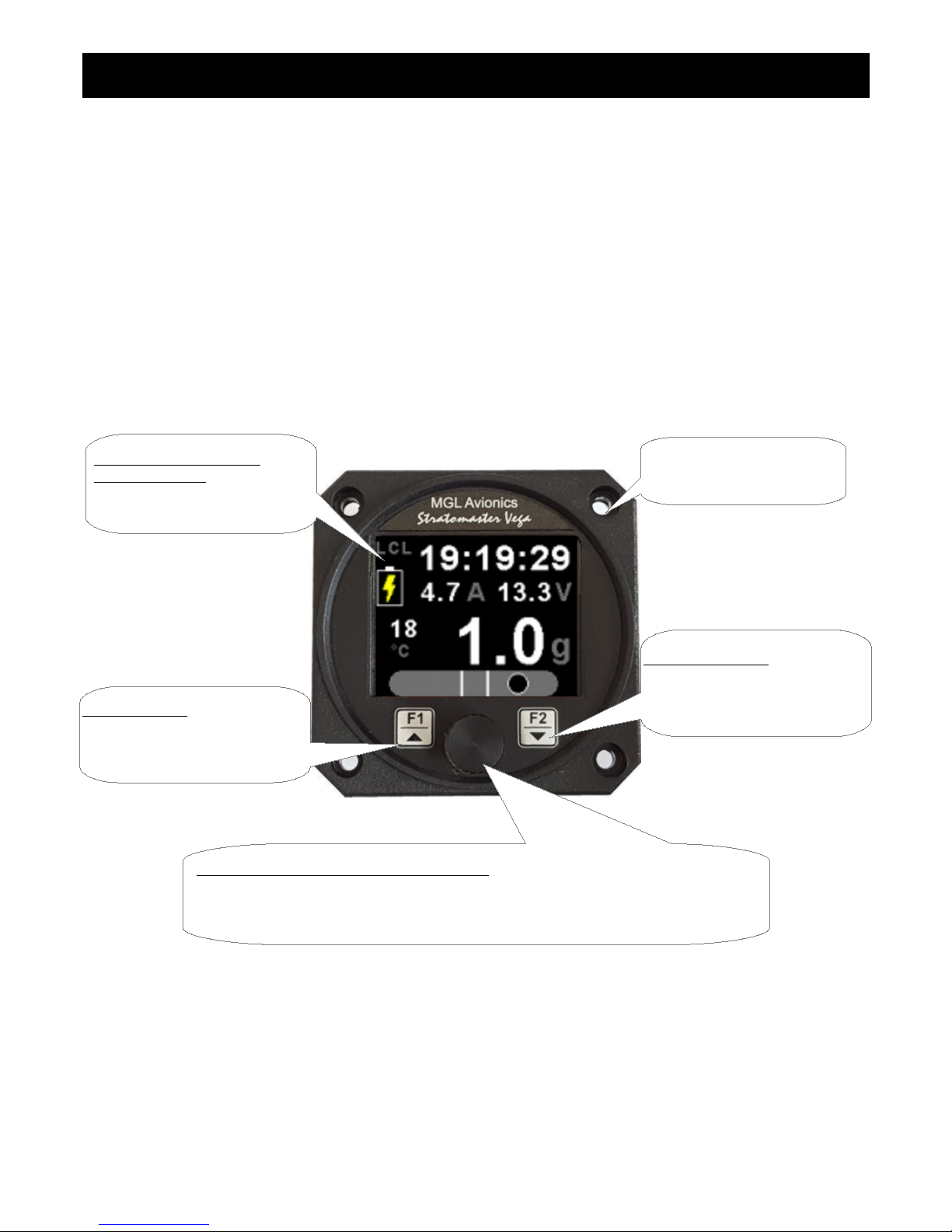
2 Layout
F2 / Down Button:
Menu System: Softkey button
Normal Display: Mode dependent,
See section 3
Sunlight readable color
graphic display:
Backlight can be adjusted in the
menu system
Rotary Control (Up/Down) & Enter Button:
Press the rotary control during the normal display screens to access the menu system.
Rotate anti/clockwise for up/down menu scrolling. Rotate the rotary control during the
normal display mode to switch between the main display screens.
F1 / Up Button:
Menu System: Softkey button
Normal Display: Mode dependent,
See section 3
2 1/4” enclosure.
Can be front or rear mounted
Page 4
Vega INFO-1 Operating Manual Page 4
3 Main Displays
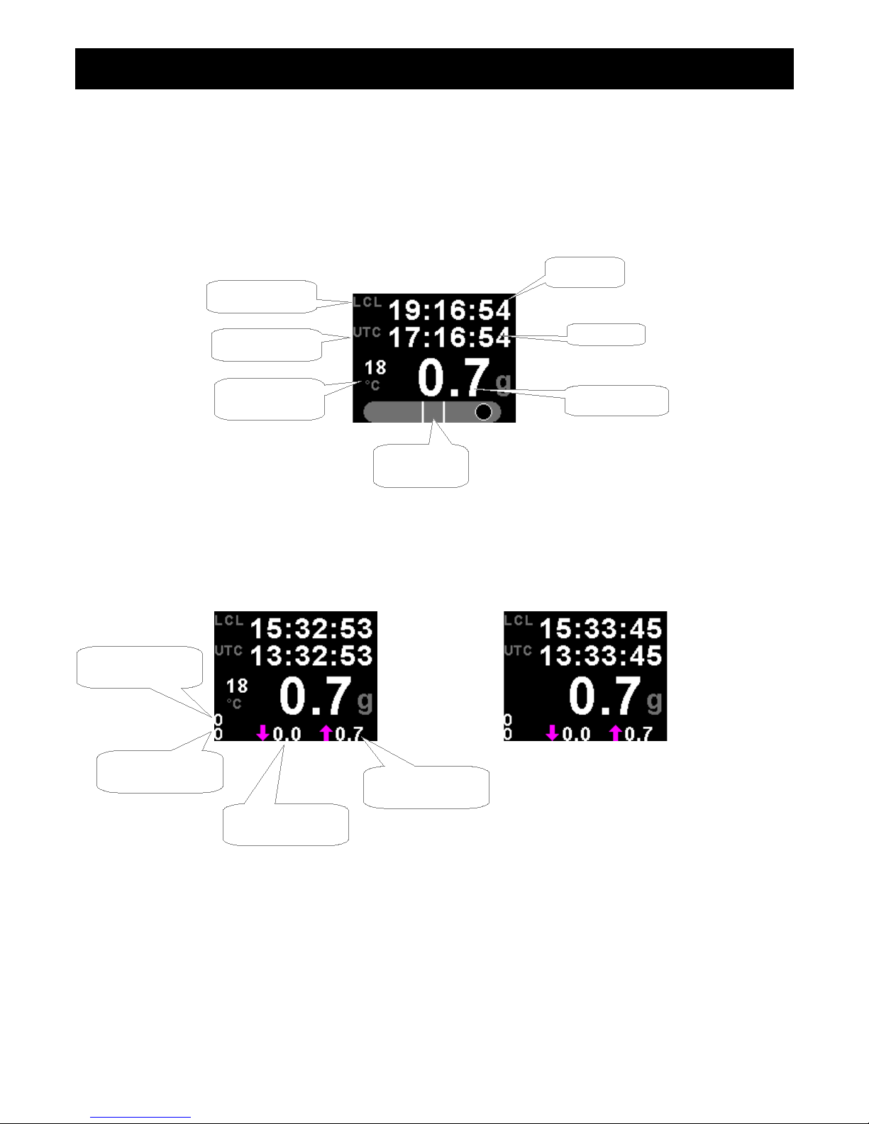
The INFO-1 has various display screens depending on the mode selected. The local time, G-force, Slip (if enabled) and
OAT (if enabled) is shown on all of the main display screens.
3.1 UTC Time Display
Slip Indicator disabled Slip Indicator & OAT disabled
Slip Indicator
(if enabled)
Local time
UTC time
OAT display
(if enabled)
Local time label
UTC label
G-force display
Maximum G-force
reached
Minimum G-force
reached
Positive G-force
cycle counter
Negative G-force
cycle counter
Page 5

Vega INFO-1 Operating Manual Page 5
3.2 Flight Timer
Slip Indicator disabled Slip Indicator & OAT disabled
Press the F1 push button to start/stop the flight timer. This push button is only active if the flight timer is set to manual.
Slip Indicator & OAT disabled, Flight Timer set for remote start/stop
Local time
G-force display
Slip Indicator
(if enabled)
Local time label
Flight timer label
Flight time
Press the F1 key to Start/Stop
the flight timer. The F1 key is
only active if the flight timer is set
to manual
Page 6
Vega INFO-1 Operating Manual Page 6
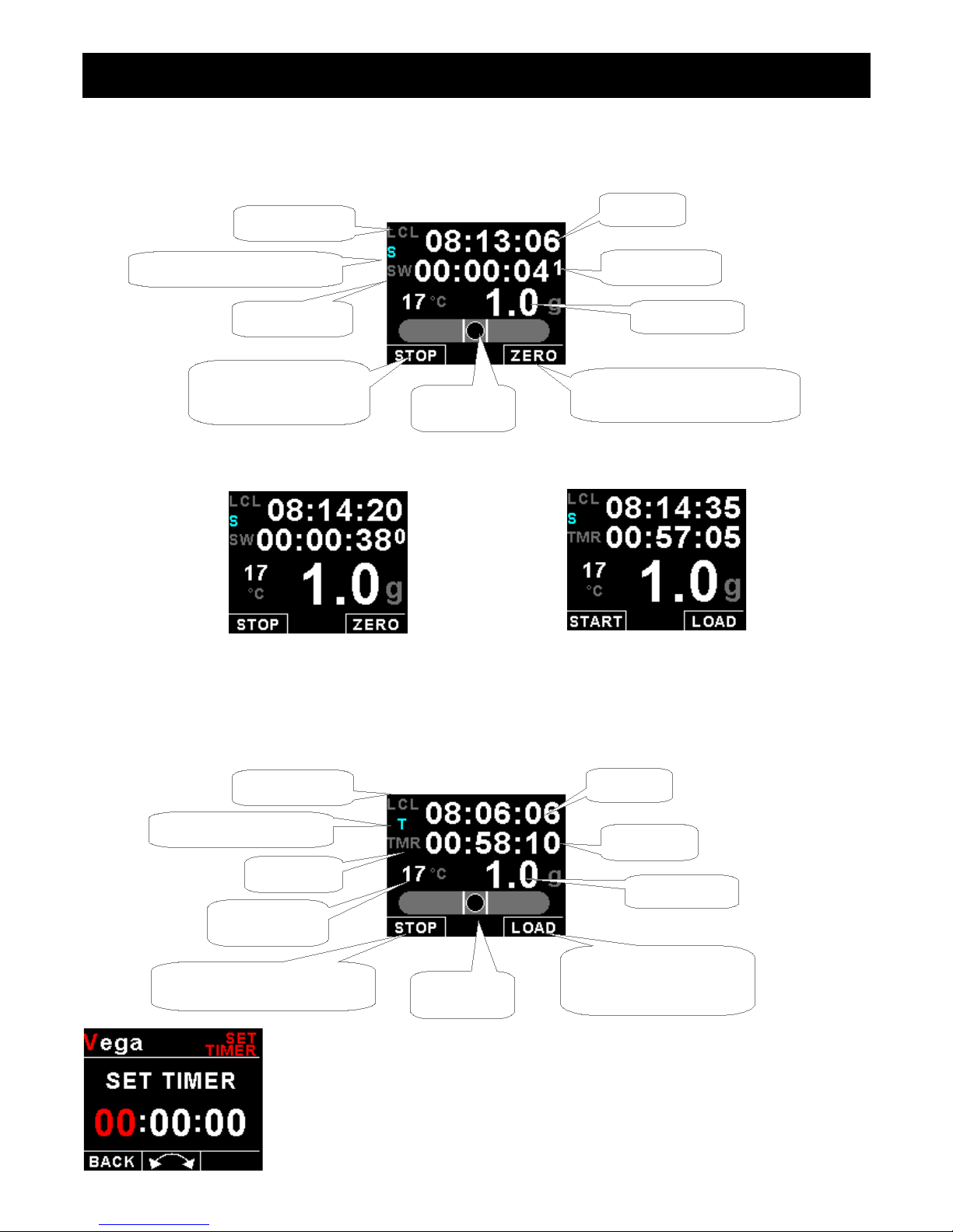
3.3 Stopwatch
The stopwatch can be started and stopped at any time and reset to zero.
Slip Indicator disabled Slip Indicator & OAT disabled
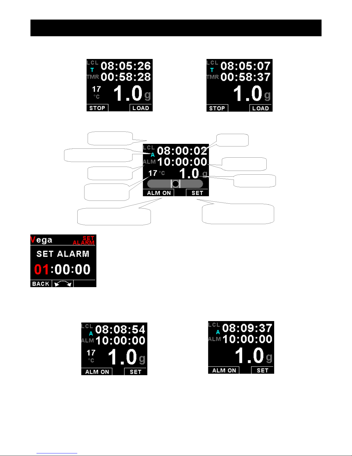
3.4 Countdown Timer
The countdown timer is loaded from a preset value. Once loaded, the timer can be started and counts down. It can be
stopped and restarted at any time.
Press the F2 key to enter the set timer screen. Use the rotary control to set the
countdown timer value. Press the F1 key to exit.
Local time
G-force display
Slip Indicator
(if enabled)
Press the F1 key to
Start/Stop the stopwatch
Stopwatch label
Local time label
Press the F2 key to reset
the stopwatch time to zero
Local time label
Timer label
Local time
Stopwatch time
Timer time
Slip Indicator
(if enabled)
Press the F1 key to
Start/Stop the countdown timer
Press the F2 key to
load the countdown timer
to a preset value
G-force display
OAT display
(if enabled)
Indicates timer is running
Indicates stopwatch is running
Page 7
Vega INFO-1 Operating Manual Page 7
Slip Indicator disabled Slip Indicator & OAT disabled
3.5 Alarm
Press the F2 key to enter the alarm setting screen as shown on the left. Use the rotary
control to set the alarm time. Press the F1 key to exit.
Slip Indicator disabled Slip Indicator & OAT disabled
Local time
Local time label
Alarm label
Alarm time
G-force display
Press the F2 key to
set the alarm time
Press the F1 key
to enable/disable the alarm
OAT display
(if enabled)
Indicates alarm is on
Page 8
Vega INFO-1 Operating Manual Page 8
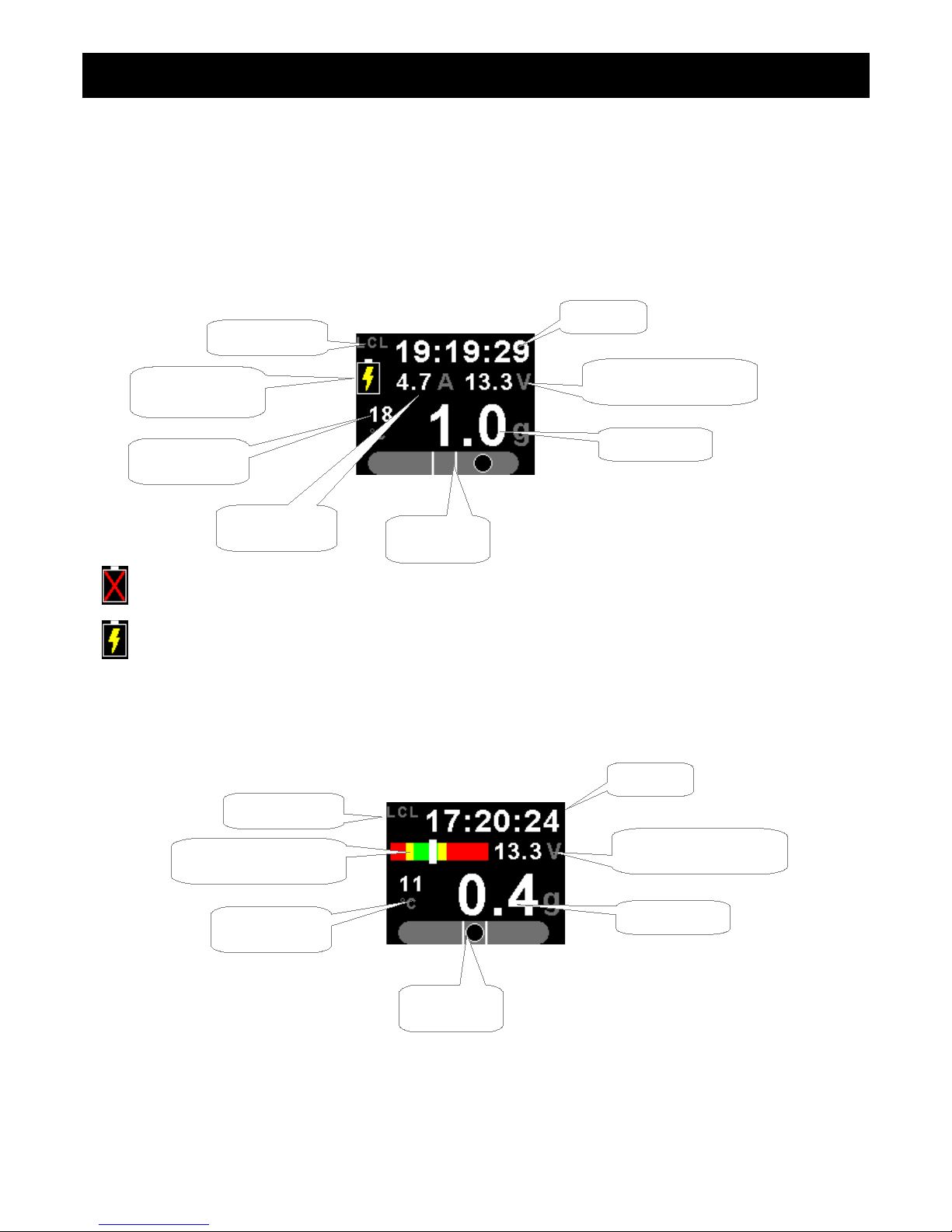
3.6 Battery Voltage / Current display
Both the battery voltage and current can be displayed. If the current measurement is disabled then the battery voltage will
be shown with a bargraph.
Dual Mode (Both battery voltage and current shown)
Battery discharging
Battery charging
Battery Voltage only (Current measurement disabled)
Slip Indicator
(if enabled)
Local time
G-force display
Local time label
Charge/Discharge
icon
OAT display
(if enabled)
Current value
Battery voltage value
Slip Indicator
(if enabled)
OAT display
(if enabled)
Local time label
Local time
G-force display
Battery voltage value
Battery voltage bargraph
Page 9

Vega INFO-1 Operating Manual Page 9
3.7 OAT (Outside Air Temperature)
The OAT display is shown on all the main displays. The OAT display can be disabled in the menu system.
3.8 G-force
The G-force display is shown on all the main displays. The cycle counter and the maximum/minimum values are only
shown on certain displays.
3.9 Maximum/Minimum Values display
Press the F1 key to reset the maximum and minimum values. If the security option has been enabled, then the correct
security code will have to be entered before you will be able to reset the maximum and minimum values.
OAT display
OAT unit
Number of times the positive
limit has been exceeded
Number of times the negative
limit has been exceeded
G-force display
Maximum negative G-force
recorded during a flight
Maximum positive G-force
recorded during a flight
Page 10

Vega INFO-1 Operating Manual Page 10
4 Menu System
Press the rotary control button during the normal display mode to enter the menu system. Use the rotary control to
navigate through the menu system.
4.1 Exiting the menu system
Press the F1 button to exit the menu system when the “EXIT” soft key is shown. All changes made during navigation of
the menu system will be saved in non-volatile memory upon exiting. The instrument will not save any changes if you
remove power before exiting the menu system.
Page 11

Vega INFO-1 Operating Manual Page 11
4.2 Flight Timer
View Flight Log:
Use the rotary control to view the next flight log entry.
Erase Flight Log:
Use this function to erase the flight log stored in the INFO-1.
FT Display:
Select to enable or disable the flight timer display.
Flight:
Select if you would like to start and stop a flight by pressing a front push button, or by using a digital input.
Page 12

Vega INFO-1 Operating Manual Page 12
4.3 G-Force Setup
Pos Alarm:
This enables or disables the positive G-force alarm.
Pos Alarm:
Enter the G-force threshold for when the positive alarm must be activated. Any G-force above this value will activate the
alarm.
Neg Alarm:
This enables or disables the negative G-force alarm.
Neg Alarm:
Enter the G-force threshold for when the negative alarm must be activated. Any G-force below this value will activate the
alarm.
Pos Cycle:
Set the positive G-force limit above which the cycle counter should increment. This would typically be set to the maximum
allowable G-force rating of your aircraft (positive G-force). The cycle count is retained if power is removed.
Neg Cycle:
Set the negative G-force limit above which the cycle counter should increment. This would typically be set to the
maximum allowable G-force rating of your aircraft (negative G-force). The cycle count is retained if power is removed.
Page 13

Vega INFO-1 Operating Manual Page 13
4.4 Time Setup
Set UTC Time:
This function is used to set the internal real time clock. The time to be entered must be
UTC in order for the system to operate correctly. Do not enter local time (unless it is the
same as UTC).
UTC is the same as Greenwich Mean Time (GMT) or Zulu time.
UTC Offset:
Enter the UTC offset for your location. The UTC offset can be adjust in half an hour increments.
UTC Display:
Select to enable or disable the UTC display.
SW Display:
Select to enable or disable the stop watch display.
TMR Display:
Select to enable or disable the countdown timer display.
ALM Display:
Select to enable or disable the alarm display.
RTC Trim:
This allows you to adjust a trimming factor that will increase the accuracy of the built in clock.
Page 14

Vega INFO-1 Operating Manual Page 14
4.5 Volts Setup
Display Max:
Select the maximum value that you want the volts bargraph to show. This can give you increased display resolution. The
bargraph is only shown if the current display is disabled.
Display Min:
Select the minimum value that you want the volts bargraph to show. This can give you increased display resolution. The
bargraph is only shown if the current display is disabled.
High Alarm:
This enables or disables the volts high alarm.
High Alarm:
Enter the voltage threshold for when the high alarm must be activated. Any voltage above this value will activate the
alarm.
High Caution:
Enter the voltage for the high caution. This is the lower value of the upper yellow band.
Low Caution:
Enter the voltage for the low caution. This is the upper value of the lower yellow band.
Low Alarm:
This enables or disables the volts low alarm.
Low Alarm:
Enter the voltage threshold for when the low alarm must be activated. Any voltage below this value will activate the alarm.
Cal:
Measure the battery voltage with a multimeter and then adjust this value to match that of the multimeters volts reading.
Page 15

Vega INFO-1 Operating Manual Page 15
4.6 Current Setup (MGL Avionics magnetic field or active shunt
required)
Current Disp:
Select to enable or disable the current display.
High Alarm:
This enables or disables the current high alarm.
High Alarm:
Enter the current threshold for when the high alarm must be activated. Any current above this value will activate the
alarm.
High Caution:
Enter the current value for the high caution.
Low Caution:
Enter the current value for the low caution.
Low Alarm:
This enables or disables the current low alarm.
Low Alarm:
Enter the current threshold for when the low alarm must be activated. Any current below this value will activate the alarm.
Page 16

Vega INFO-1 Operating Manual Page 16
Zero Sensor:
Select this function to indicate to the INFO-1 that zero current is flowing through the MGL
current sensor. This is best done with the MGL current sensor disconnected from the
main current supplying conductor.
Gain:
Adjust the gain factor until the current is reading correctly. It will be best if a multimeter can be inserted in series with the
current supplying conductor and the gain calibration adjusted until the INFO-1 matches that of the multimeter. Please see
the MGL current sensor documentation for more information.
In the case of the MGL magnetic field current sensor, This will depend on the distance and the method that is used to
attach the MGL current sensor to the main current supplying conductor.
Page 17

Vega INFO-1 Operating Manual Page 17
4.7 OAT (Outside Air Temperature) Setup
OAT Display:
Select to enable or disable the OAT display.
Temp Unit:
Select whether you want the OAT to be displayed in degrees Celsius (ºC) or in degrees Fahrenheit (ºF).
High Alarm:
This enables or disables the OAT high alarm.
High Alarm:
Enter the temperature threshold for when the high alarm must be activated. Any temperature above this value will activate
the alarm.
High Caution:
Enter the temperature for the high caution. This is the lower value of the upper yellow band.
Low Caution:
Enter the temperature for the low caution. This is the upper value of the lower yellow band.
Low Alarm:
This enables or disables the OAT low alarm.
Low Alarm:
Enter the temperature threshold for when the low alarm must be activated. Any temperature below this value will activate
the alarm.
OAT Cal:
During the factory calibration a factor has been determined and entered here that will give you an accurate OAT reading.
If you find this value is incorrect then adjust the calibration factor until the INFO-1 OAT matches that of a precision
thermometer. Calibration can only be done in Celcius (ºC).
Page 18

Vega INFO-1 Operating Manual Page 18
4.8 Slip Setup
Slip Display:
Select if you would like to enable the slip indicator to be shown on the bottom of the display.
Slip Sense:
Select if you want the slip to have a high sensitivity or a low sensitivity setting.
Slip Zero:
This function allows you to set your slip indicator to exactly zero even if your aircraft tends to fly slightly wing down. The
procedure is to place the aircraft in a stable, straight and level attitude during calm flight conditions and then select this
function. To cancel the correction, place your sensor absolutely horizontal (use a spirit level) and select the function
again.
Page 19

Vega INFO-1 Operating Manual Page 19
4.9 MISC Setup (Miscellaneous Setup)
Backlight:
Select this menu option to adjust the backlight brightness.
Security Setup:
Select this menu option if you want to password protect the menu system.
Information:
This menu option displays information about the unit.
Page 20

Vega INFO-1 Operating Manual Page 20
Default Settings:
Select this menu option to reset all the settings to factory defaults.
4.10 ADC Values
This menu displays the ADC values from the various sensors.
5 Loading factory default settings
Press and hold the F1/Up button and rotary control during power up to load the preprogrammed factory default settings. The following screen will be displayed:
Factory default settings can also be loaded in the Miscellaneous setup menu.
6 Error Messages
Unit settings CRC error. Load default settings to restore to factory defaults. If the error
message still persists then it could possibly be a non-volatile memory failure in which
case the instrument will then have to be returned to the factory.
Internal flash CRC error. The instrument does a firmware check on the program when
power is applied to the instrument . If the program is corrupt in any way then the internal
flash CRC error will be displayed. Reload the instruments firmware and load default
settings. If the error message still persists then it could possibly be an internal flash
memory failure in which case the instrument will then have to be returned to the factory.
Calibration constants CRC error. The instrument could possibly have a non-volatile
memory failure in which case the instrument will then have to be returned to the factory.
Page 21

Vega INFO-1 Operating Manual Page 21
Max Values CRC error. Load default settings to restore to factory defaults. If the error
message still persists then it could possibly be a non-volatile memory failure in which
case the instrument will then have to be returned to the factory.
7 Specifications
Operating Temperature Range -10ºC to 60ºC (14ºF to 140ºF)
Storage Temperature Range -20ºC to 80ºC (-4ºF to 176ºF)
Humidity <85% non-condensing
Power Supply
8 to 30Vdc SMPS (switch mode power supply) with built in 33V over
voltage and reverse voltage protection
Current Consumption
Approx. 73mA @ 13.8V (backlight highest setting), 33mA @13.8V
(backlight lowest setting)
Display
1.8” 160x128 pixel active matrix TFT display.
1000 cd/m2
Sunlight readable with anti-glare coating
LED Backlight is user configurable
Alarm Output
Open collector transistor switch to ground
Maximum rating 0.25A
ADC 12 bit
Dimensions see Vega series dimensional drawing
Enclosure 2 1/4” ABS, black in color, front or rear mounting. Flame retardant.
Weight Approx. 120 grams (Instrument excluding cables)
Non-volatile memory storage 100000 write cycles
Voltage measurement range Up to 32Vdc
Voltage resolution 0.1V
Current shunts supported MGL Avionics magnetic field or MGL Avionics active current shunt
G-force range +-16g typical
OAT Temperature Sender type Semiconductor LM335 (ON Semiconductor)
Internal battery type CR2032
8 Operating the alarms
The alarm output can be used to switch an external alarm indicator. The external alarm switch is an open collector
transistor switch to ground with a maximum rating of 0.25A DC. It is possible to wire the alarm contacts of several
Stratomaster instruments in parallel should this be desired. To avoid false activation of the alarms, the alarm function is
only active 10 seconds after the instrument has powered up.
9 Firmware Upgrading
The INFO-1 can be upgraded in the field by connecting the RS232 port to a PC and running the firmware update
program. Note that only the RS232 port can be used to upgrade the firmware.
Please see the Vega firmware upgrading document for more information.
Page 22

Vega INFO-1 Operating Manual Page 22
10 Installation
10.1 Connection Diagram
The use of an external 1A fuse is recommended. Connect the supply terminals to your aircrafts power supply. The INFO1 can be used on both 12V and 24V without the use of any pre-regulators. Ensure that the supply voltage will not drop
below 8V during operation as this may result in incorrect readings.
Page 23

Vega INFO-1 Operating Manual Page 23
10.2 Cable connections
Main connector (D15HD connector: Unit Female, Cable Male)
11 Changing the internal battery
The INFO-1 uses an internal Lithium battery to supply power to run the internal clock. If you find the INFO-1 looses time
when you switch off main power you should replace the battery. This battery is of type CR2032. It is used in many
calculators and similar equipment and is easy to obtain. Remove the 2 securing nuts next to the D-15 connector and
remove the unit from its enclosure. The battery holder is located on the circuit board behind the display. Observe correct
polarity when installing a new battery. The side marked “+” will be viewable once the battery is inserted.
12 Cleaning
The unit should not be cleaned with any abrasive substances. The screen is very sensitive to certain cleaning materials
and should only be cleaned using a clean, damp cloth.
13 Warranty
This product carries a warranty for a period of one year from date of purchase against faulty workmanship or defective
materials, provided there is no evidence that the unit has been mishandled or misused. Warranty is limited to the
replacement of faulty components and includes the cost of labor. Shipping costs are for the account of the purchaser.
Note: Product warranty excludes damages caused by unprotected, unsuitable or incorrectly wired
electrical supplies and or sensors, and damage caused by inductive loads.
Warning: The INFO-1 is not waterproof, serious damage could occur if the unit is exposed to
water and/or spray jets.
D15HD Pin Color Function
1 Red 8-30Vdc power via power switch / circuit
breaker and fuse.
2 Black Ground. Connect the ground to the engine
block, and the engine block to the battery
negative. Do not connect the INFO-1 ground
directly to the battery negative. This must be
routed via the engine block.
3 - RS232 Transmit data (Firmware upgrading)
4 - RS232 Receive data (Firmware upgrading)
5 Green Current sender input
7 Orange OAT Sender input
10 Grey Flight timer remote start/stop
(Leave open if remote start stop not required)
Low = Run flight timer
Open = Stop flight timer
15 White Alarm Output (Open collector)
Page 24

Vega INFO-1 Operating Manual Page 24
14 Disclaimer
Operation of this instrument is the sole responsibility of the purchaser of the unit. The user must make themselves familiar
with the operation of this instrument and the effect of any possible failure or malfunction.
This instrument is not certified by the FAA. Fitting of this instrument to certified aircraft is subject to the rules and
conditions pertaining to such in your country. Please check with your local aviation authorities if in doubt. This instrument
is intended for ultralight, microlight, homebuilt and experimental aircraft. Operation of this instrument is the sole
responsibility of the pilot in command (PIC) of the aircraft. This person must be proficient and carry a valid and relevant
pilot’s license. This person has to make themselves familiar with the operation of this instrument and the effect of any
possible failure or malfunction. Under no circumstances does the manufacturer condone usage of this instrument for IFR
flights.
IMPORTANT NOTICE:
You must make your own determination if the products sold by MGL Avionics are safe and effective for your intended
applications. MGL Avionics makes no representations or warranties as to either the suitability of any of the products we
sell as to your particular application or the compatibility of any of the products we sell with other products you may buy
from us or anywhere else, and we disclaim any warranties or representations that may otherwise arise by law. Also, we
offer no specific advice on how to install any of the products we sell other than passing along anything that may have
been provided to us by the manufacturer or other issues. If you are in need of further information or guidance, please turn
to the manufacturer, FAA Advisory Circulars and guidance materials, the Experimental Aircraft Association, or other
reputable sources.
Other instruments in the Stratomaster Vega series
AHRS-1 Artificial Horizon and Magnetic Compass Indicator
ALT-5 Altimeter and Vertical Speed Indicator (VSI)
ASI-4 Airspeed Indicator (ASI)
ASV-1 Altimeter, Airspeed (ASI) and Vertical Speed Indicator (VSI)
EMS-1 Engine Monitoring System
FF-4 Fuel Computer
INFO-1 Information Display (G-Force meter, UTC and Local Time, Slip Indicator, Outside Air
Temperature (OAT), Battery Voltage, Current and charge display, Flight Timer & Flight
Log, Stopwatch, Countdown Timer and Alarm)
MAG-1 Magnetic Compass Indicator
MAP-3 Manifold Pressure and RPM Indicator
RPM-1 Universal Engine / Rotor RPM Indicator
TC-4 4 Channel Thermocouple (EGT/CHT) Indicator
TP-3 4 Channel Universal Analog Input (Pressure/Temperature/Current/Volts) Indicator
The manufacturer reserves the right to alter any specification without notice.
 Loading...