

Page 1
Operating Instructions
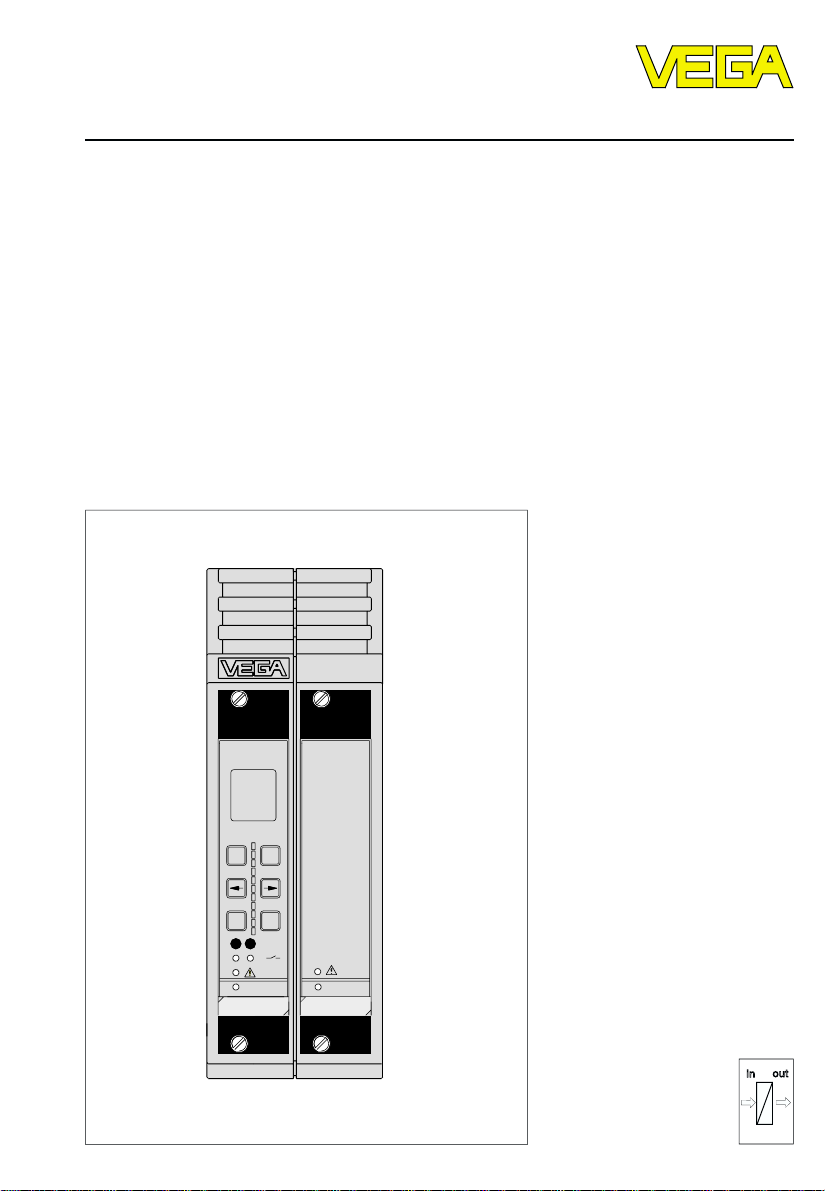
Housing type 506
Level and Pressure
ESC
%
100
+
-
OK
CONNECT
2
1
on
VEGAMET
514V
on
VEGATRENN
547V Ex
out
in
Page 2

Contents
Safety information ........................................................................ 2
Note Ex-area ................................................................................ 2
1 Product description
1.1 Function and configuration .................................................. 3
1.2 Types and versions ............................................................. 4
1.3 Technical data ....................................................................... 4
1.4 Dimensions ........................................................................... 5
2 Mounting
2.1 General ................................................................................. 6
2.2 Coding with Ex-instruments ................................................ 6
2.3 Transparent cover ............................................................... 6
2.4 Retrofitting of the housing with a power supply unit ......... 6
3 Electrical connection
3.1 Terminal coordination on VEGAMET ................................... 9
3.2 Connection examples ........................................................ 10
Contents
Safety information
The described module must only be installed
and operated as described in these operating
instructions. Please note that other action can
cause damage for which VEGA does not take responsibility.
Note Ex-area
Please note the approval documents attached
(yellow binder), and especially the included
safety data sheet.
2 Housing type 506
Page 3

Product description
1 Product description
1.1 Function and configuration
The housing type 506 is used for single
mounting of a signal conditioning instrument
for VBUS-sensors of series 500 (width 5 TE =
25,4 mm) and, additionally for VEGATRENN
547V Ex or 548V Ex separator also with 5 TEwidth.
The housing can be either screwed directly
to the mounting plate or mounted to a carrier
rail (35 x 15 acc. to EN 50 022).
The housing consists generally of three components:
- Socket with terminals
The connection terminals for the sensors
are located at the bottom and the ones for
the outputs and the power supply on top of
the socket. Therefore, the necessary separation between intrinsically safe and notintrinsically safe circuits in Ex-applications
is ensured. For carrier rail mounting an appropriate adapter is integrated in the socket.
- Upper part of the housing with guide rails
and ventilation slots. Sufficient ventilation is
also ensured when connecting several
housings in series. No external ventilation
necessary.
- The attached bag includes blue Ex-labels
and coded pins.
If you already have a power supply of
20 … 53 V AC or 20 … 72 V DC available,
you can use the housing without power supply unit.
If you only have other supply voltages available, use a housing with integrated power
supply unit.
The power supply unit is suitable for a voltage range of 90 … 250 V AC and DC and
can power the module units.
A later retrofitting of the housing with a power
supply unit is possible.
Note:
The housing type 506 is only designed for
series 500 instruments:
- VEGAMET 514V, 514VD, 515V
- VEGATRENN 547V Ex, 548V Ex
The power supply unit of the housing provides no galvanic isolation from the supply
voltage. Series 500 instruments realise the
galvanic isolation in the signal conditioning
instrument.
The module instruments of the new series
500
- VEGAMET…
- VEGATRENN…
are generally provided for a power supply of
20 … 53 V AC or 20 … 72 V DC.
Housing type 506 3
Page 4
Product description
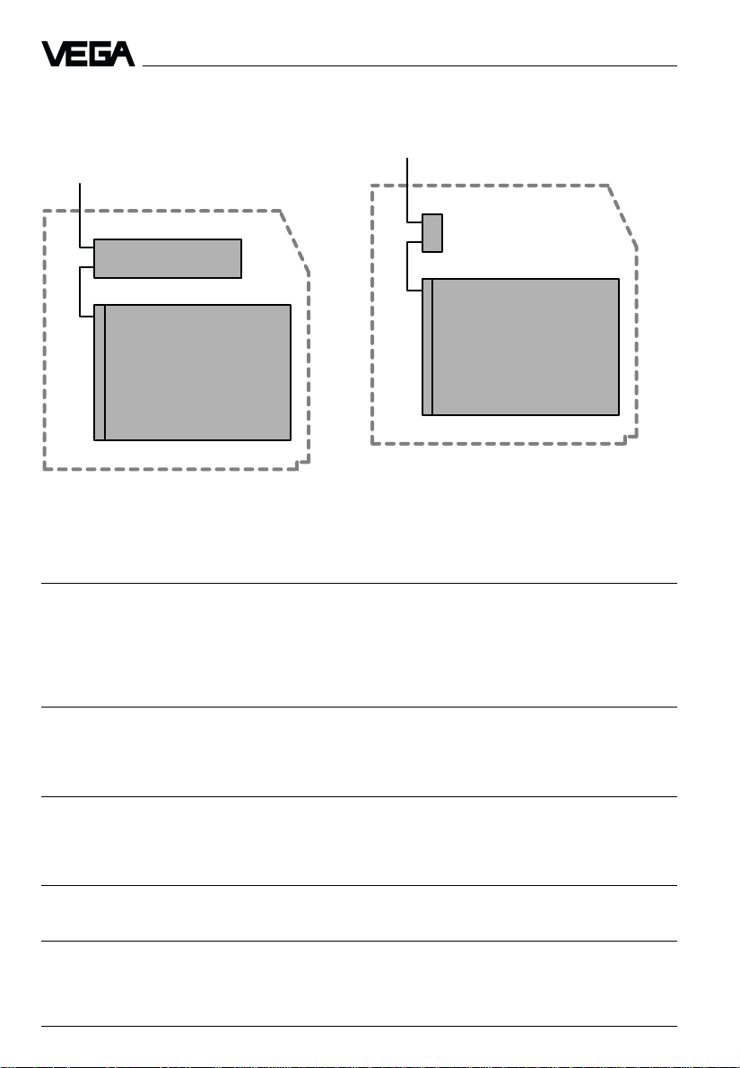
1.2 Types and versions
Housing with power supply unit
90 … 250 V AC
Power supply unit
Signal conditioning instrument
Housing without power supply unit
20 … 53 V AC
20 … 72 V DC
Adapter plug
Signal conditioning instrument
1.3 Technical data
Power supply
Supply voltage 20 … 72 V DC
Supply voltage with
integral power supply unit 90 … 250 V AC galvanically not isolated
20 … 53 V AC
(18 W; 50 VA)
Material
Terminal socket PPE (Noryl) black, self-extinguishing
Upper part of housing PPE (Noryl) grey (RAL 7036),
self-extinguishing
Multipoint connectors
Number 2
Version acc. to DIN 41 612, series F, 48-pole, 3 rows,
d, b, z (partly equipped)
Strip terminal
Cross-section area of conductor max. 2,5 mm
2
Protection classes
Protection IP 20
Protection class II
Overvoltage categories II
4 Housing type 506
Page 5

Product description
Mounting
Carrier rail 35 x 15 acc. to EN 50 022
Mounting plate 3 holes with 4,5 mm ø
3 screws M4 x 12 mm
Mechanical data
Dimensions W x H x D = 62 x 180 x 198 mm
Weight approx. 650 g
Ambient conditions
Permissible ambient temperature -20°C … +60°C
Storage and transport temperature -40°C … +80°C
CE-conformity
Housing type 505 is manufactured according to the European standard and meets the
protective regulations of EMVG (89/336/EWG) and NSR (73/23/EWG). The conformity has
been judged acc. to the following standards:
EMVG Emission EN 50 081 - 1: 1992
Susceptibility EN 50 082 - 2: 1995
NSR EN 61 010 - 1: 1993
1.4 Dimensions
12
Upper part of
housing
200
Terminal socket
6
Front side
180
VEGAMET VEGASEL
62
ø4,5
Holes
41,5
106,7
19,4
13,7
10,3
Housing type 506 5
Page 6

2 Mounting
2.1 General
The housing type 506 can be screwed directly on a mounting plate (see "Dimensions,
holes") or placed on a carrier rail (35 x 15
acc. to EN 50 022). To do this, it is necessary
to loosen the two screws on the front of the
housing and to remove the upper part of the
housing from the socket.
For placing on carrier rail or loosening from
the carrier rail, unlock the holding strap with a
screwdriver in the lower rectangular opening
of the socket.
Holding strap (orange)
Mounting
2.2 Coding with Ex-instruments
To avoid a not-Ex-instrument being inserted
into the housing instead of the separator, the
right multipoint connector of the housing is
provided with a coded pin (position c23). A
hole is provided in the appropriate position
on the multiple plug of the VEGATRENN 547V
Ex and 548V Ex separators.
2.3 T ransparent cover
The module units can be provided with a
lockable transparent cover to avoid unauthorised adjustment.
The transparent covers are supplied along
with the module units.
2.4 Retrofitting of the housing with a
power supply unit
Please proceed as follows to retrofit a power
Wire the terminals acc. to the connection plan
(see either "3 Electrical connection", or the
operating instructions of the signal conditioning instrument to be installed, or the separator).
The designations of the terminals correspond
to those on the multipoint connector on the
rear of the signal conditioning instrument. The
exceptions are the sensor connection terminals, see "3 Electrical connection".
6 Housing type 506
supply unit:
- First of all make sure that the supply volt-
age is disconnected on the terminal strips
of the socket!
- Loosen the two hold screws on the front of
the housing and remove the upper part of
the housing (the hold screws are only
accessible when there is no module card in
the housing).
- Shift the power supply board into the guide
rails of the upper part of the housing. Note
the position of the connection plug.
Page 7

Mounting
Guide rail
Power supply
board
Connection plug
Terminal strips
Adapter plug
Socket
- Insert the red safety pin through the gaps
of the power supply board and the guide
rail. This fastens the power supply board.
Gap
Safety pin
- Remove the adapter plug from the housing
socket.
- Insert the upper part of the housing into the
socket again, tighten the two screws on the
housing front.
- Now you can connect the supply voltage
for the power supply unit (90 … 250 V AC)
on the terminal strips of the socket.
Housing type 506 7
Page 8

3 Electrical connection
The designations of the terminals are identical
to those on the multiples plugs of the signal
conditioning instruments. Exception: Sensor
terminals.
Module for adapter plug. Remove this
adapter plug when inserting a power
supply board (90 … 250 V AC/DC).
Hole for screwing on a mounting plate
Thread for the housing fastening
Multipoint connector, module for
VEGATRENN 547V Ex or 548V Ex
Multipoint connector, module for
VEGAMET
Ex-coded pin (c23)
Electrical connection
Holding strap for carrier rail mounting
Holes for screwing on mounting plate
Sensor terminals
8 Housing type 506
Page 9

Electrical connection
3.1 Terminal coordination on VEGAMET
VEGAMET 514V 514VD 515V
z6b6d
z10b10d
z12b12d
+ –
d22d
24
+ –
b22b
24
b22b
24
d22d
24
+ –
d16d18d
+ –
b16b18b
+ –
z16z18z
d16d18d
6
10
12
z
22
z
24
z
–
24
z
+
22
20
20
20
Fail safe relay • • •
Level relay 1 • • •
Level relay 2 • • •
Correction signal input 4 • • •
Correction signal input 5 •
DISBUS-output • • •
Current output 1 • • •
Current output 2 • • •
Current output 3 • •
+–
20
Voltage output 1 • • •
+–
b16b18b
20
+–
z16z18z
20
12
34 56 78
+–
+–+–+–
Voltage output 2 • • •
Voltage output 3 • •
with VEGATRENN 547V Ex • • •
1234
Sensor 1
12 34 56 78
+ – + –
Sensor 1
Sensor 2
(only with VEGAMET 515V)
Housing type 506 9
1234
Sensor 2 (only with VEGAMET 515V)
with VEGATRENN 548V Ex • • •
Page 10

Electrical connection
3.2 Connection examples
VEGATRENN 547V Ex
VEGATRENN 547V Ex can power max.
- two Ex-ultrasonic sensors VEGASON
series 80
- two Ex-radar sensors VEGAPULS 81
- a combination of both
via intrinsically safe circuits in four-wire technology and transmit their digital measured
data.
Processing
Sensor
Processing
VEGAMET 514V, 514VD
VEGATRENN 547V Ex
Not-Ex-area
Ex-area
VEGAMET 515V
VEGATRENN 547V Ex
VEGATRENN 548V Ex
VEGATRENN 548V Ex can power max.
- two hydrostatic pressure transmitters
series D84 … D87
- two ultrasonic sensors VEGASON
51V … 53V
- two radar sensors VEGAPULS 51V … 56V
via intrinsically safe circuits in two-wire technology and transmit their digital measured
data.
Processing
Sensor
1
Processing
VEGAMET 515V
VEGATRENN 548V Ex
Not-Ex-area
Ex-area
Sensor
2
VEGAMET 515V
VEGATRENN 548V Ex
Not-Ex-area
Ex-area
Sensor
2
VEGAMET 514V, 514VD
VEGATRENN 548V Ex
Not-Ex-area
Ex-area
Sensor
1
Not-Ex-area
Ex-area
Sensor
2
Sensor
1
Processing
Sensor
10 Housing type 506
Page 11

Notes
Housing type 506 11
Page 12

VEGA Grieshaber KG
Am Hohenstein 113
D-77761 Schiltach
Phone (0 78 36) 50 - 0
Fax (0 78 36) 50 - 201
e-mail info@vega-g.de
ISO 9001
The statements on types, application, use and operating conditions of
the sensors and processing systems correspond to the actual
knowledge at the date of printing.
Technical data subject to alteration.
2.23 471 / April ’99
 Loading...