

Page 1
Model HB-3Plus
Headset Adaptor Panel
Technical Manual
For use with Software Versions 2.00 or Higher
December 12, 2006 P.N. 804138 Rev C
Page 2

HB-3Plus Headset Adaptor Box i
Table of Contents
1
General ...................................................................................4
1.1 Accessories ..................................................................................................................... 4
2 Installation..............................................................................5
2.1 HB-3Plus Mounting........................................................................................................ 5
2.2 HB-3Plus Setup............................................................................................................... 5
2.2.1 HB3Plus Jumper Positions ..................................................................................... 5
2.2.2 PC/Console Mode................................................................................................... 5
2.2.3 Headset I and II Connections..................................................................................5
2.2.4 Desk Microphone Connection ................................................................................6
2.2.5 Headset ON/OFF switch......................................................................................... 6
2.2.6 Radio Rx Mute w/PTT – Version 2.1 or Higher..................................................... 6
2.3 Rear Panel Connections.................................................................................................. 7
2.3.1 Power Supply Connection....................................................................................... 7
2.3.2 Serial Connection.................................................................................................... 7
2.3.3 Relay Connections.................................................................................................. 7
2.3.4 AUX IN Connections.............................................................................................. 7
2.3.5 Recorder Connections.............................................................................................8
2.3.6 Footswitch Connections.......................................................................................... 8
2.3.7 +9VDC Output Connection ....................................................................................8
2.3.8 PC Sound Card Connections................................................................................... 9
2.3.9 Console Connections .............................................................................................. 9
2.3.10 NENA Phone Connections ................................................................................... 10
2.4 Software Version .......................................................................................................... 10
2.4.1 Software/Hardware Match Up.............................................................................. 10
2.4.2 Determine The Software Version .........................................................................10
3 Audio Level Adjustments....................................................11
3.1 Desk Microphone TX Level .........................................................................................11
3.2 NENA Phone Level ......................................................................................................11
3.3 Recorder Level.............................................................................................................. 11
3.4 Headset Transmit Level................................................................................................ 11
4 Component Location and Parts Lists................................12
5 Warranty, Service, Repair, and Comments:......................13
6 HB-3Plus Specifications .....................................................14
Table of Figures
Figure 1 HB-3Plus Front View....................................................................................................... 5
Figure 2 Desk Mic Connector......................................................................................................... 6
Figure 3 HyperTerminal Screen...................................................................................................... 6
Figure 4 HB-3Plus Rear View........................................................................................................ 7
Figure 5 Relay Connections............................................................................................................ 7
Figure 6 Recorder and AUX IN Connections................................................................................. 8
Figure 7 Footswitch Connections ...................................................................................................8
Figure 8 HB-3Plus to PC Connection Diagram.............................................................................. 9
Page 3

HB-3Plus Headset Adaptor Box iii
Figure 9 HB-3Plus To Console Connector Pin-out ........................................................................9
Figure 10 NENA to HB3Plus Connections and Pinout................................................................ 10
Figure 11 HB3Plus Hardware Identification Jumper.................................................................... 10
iii
Page 4

4 HB-3Plus Headset Adaptor Box
1 General
The Vega HB-3Plus Headset Interface Box is a reliable method for connecting a desk microphone,
headsets and footswitch controls to any computer running Vega’s C-Soft program or any Vega dispatch
console. A bi-color front panel LED indicates power (green) or active PTT (red).
The HB-3Plus connects directly to the handset jack of the dispatch control console or a PC operating with
the Vega C-Soft dispatch software. In the console mode, an RJ11 4 conductor cable provides the
connection from the HB-3Plus to the console. Connections to the PC serial port and sound card provide
PTT, monitor, relay and Aux input control in the PC mode.
The HB-3Plus also provides a connection to any telephone device with a NENA I/O port, allowing for a
single headset to be shared by the radio and phone system. When the phone set is taken off-hook, the
headset microphone audio is routed to the phone system and selected radio is transferred back to the
SELECT speaker. Telephone audio is routed to the headset as long as the system is off-hook.
The HB-3Plus Features:
• 2 Dual ¼’ headset jacks
• Independent SELECT volume controls
• Switch selectable headset on/off
• 1 Desk microphone input
• 3 Independent footswitch inputs
• Power and PTT LED indicator
• 1 NENA I/O port
• 2 AUX relays (Form C contacts)
• 2 AUX IN TTL inputs
• Balanced common recorder output
• Separate balanced UNSELECT audio recorder output
• +9VDC 50mA output
Jumper Selectable Options:
• PC/Console Mode
• C-Soft mic output level set (Mic/Line)
• Electret/Dynamic desk mic select
• Route UNSELECT audio to headsets
• Route UNSELECT audio to common recorder output
• +9VDC/GND (Pin 6 of footswitch terminal block)
1.1 Accessories
Several optional accessories are available for the HB-3Plus.
Part Number
0108024 FS-1 Footswitch.
24901611 Stereo Headset with Microphone and inline PTT switch.
302070100 DH2000 Dispatcher Headset – Mono
302070200 DH2200 Dispatcher Headset – Dual sided Mono
302068000 LC1500 Lower cord, 15 ft.
302068001 LC2500 Lower cord, 25 ft.
0118022 MD-MS Electret Desk Microphone
301905000 6513C Dynamic Desk Microphone
: Description:
Page 5
HB-3Plus Headset Adaptor Box 5
2 Installation
2.1 HB-3Plus Mounting
The HB-3Plus may be mounted either under or along the side of a dispatch position, choose a
location that allows for easy headset connection and is free of direct hits from chair arms and
personnel knees.
2.2 HB-3Plus Setup
2.2.1 HB3Plus Jumper Positions
Jumper Function Factory Set Position
JMP1 PC Mode Mic Output Level Set – Mic/Line Level A – Mic Level
JMP2 Electret/Dynamic Desk Mic Set A – Electret Desk Mic
JMP3 SELECT/UNSELECT Headset II Audio B – SELECT Audio Only to Headset
JMP7 Pin 6 Relay Block Function – GND/+9VDC A – GND
JMP8 PC/Console Mode Select A – PC Mode
JMP9 Route UNSELECT Audio to Common Recorder A – UNSELECT Audio to Recorder
JMP12 SELECT/UNSELECT Headset I Audio B – SELECT Audio Only to Headset
Table 1 HB3Plus Jumpers
2.2.2 PC/Console Mode
Operation of the HB-3Plus with Vega C-Soft or tone remote consoles is set by JMP8.
A – PC Mode
B – Console Mode
Note: The HB3Plus Must Be Reset When Changing Modes.
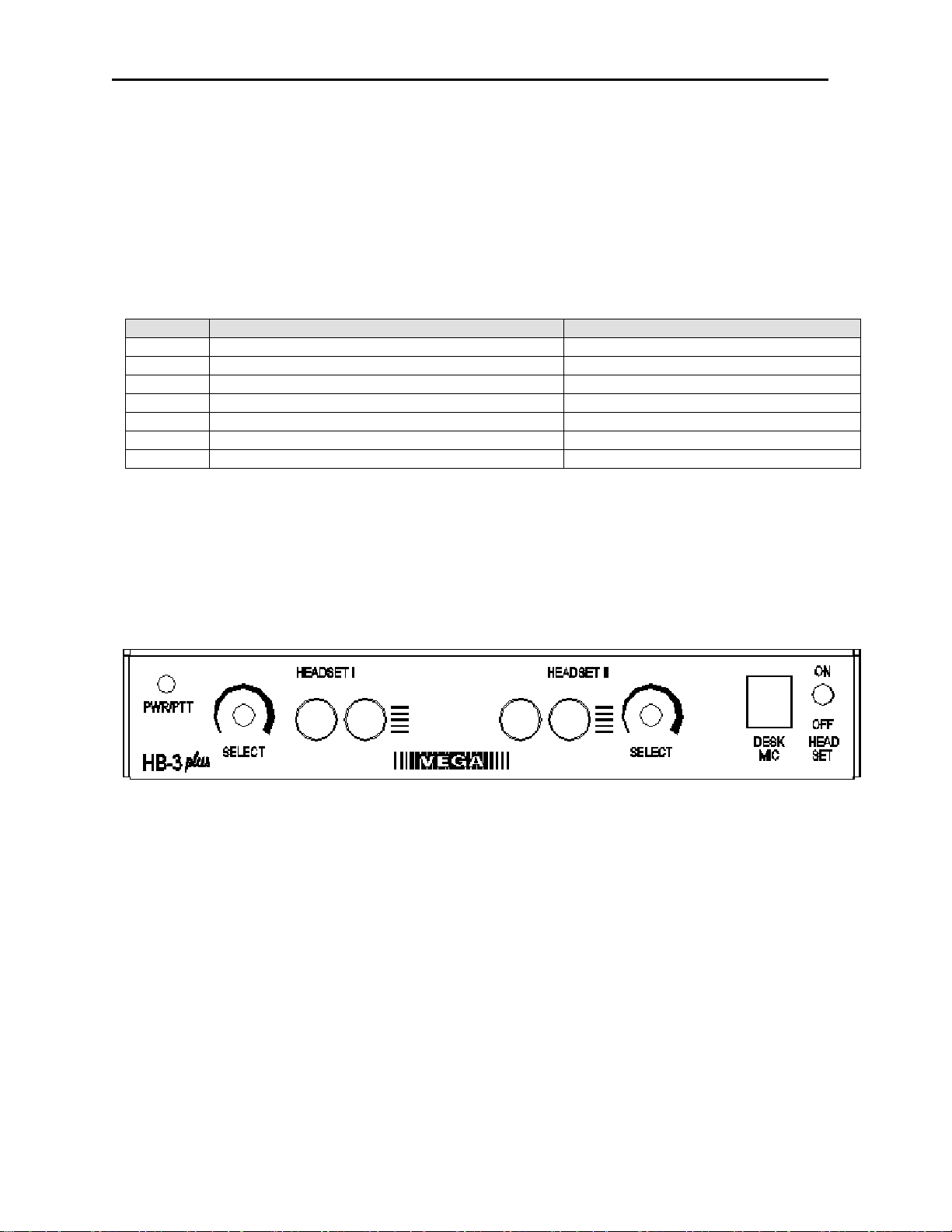
Figure 1 HB-3Plus Front View
2.2.3 Headset I and II Connections
The HB-3Plus operates with either 4 or 6 wire Dual ¼” Phone Jack plugs. The standard
configuration for the HB-3Plus is for operation with a 6-wire plug configuration. The horizontal lines
adjacent to the right phone jack of each headset pair indicate the negative polarity of the mic bias.
Headset I
JMP12 – Routes SELECT or UNSELECT audio to the headset I
A – UNSELECT and SELECT audio to headset I
B – SELECT only audio to headset I
Cutting the small trace between JMP13 disables the PTT function for 4-wire headset operation
Headset II
JMP3 – Routes SELECT or UNSELECT audio to the headset II
A – UNSELECT and SELECT audio to headset II
B – SELECT only audio to headset II
Cutting the small trace between JMP6 disables the PTT function for 4-wire headset operation.
Page 6
6 HB-3Plus Headset Adaptor Box
2.2.4 Desk Microphone Connection
The HB-3Plus is designed to operate with the MD-MS electret
desk microphone or the Model 6513C dynamic desk
microphone. Internal jumper JMP2 selects the electret or
dynamic microphone configuration.
A – Electret
B – Dynamic
When using a desk microphone the Headset On/Off switch
should be in the OFF position to route SELECT audio to the
speaker.
Figure 2 Desk Mic Connector
2.2.5 Headset ON/OFF switch
The headset ON/OFF switch is used to provide hook signaling to a Vega dispatch console or CSoft application. When OFF, SELECT audio is routed from the headset to the speaker. When
using a desk microphone the switch should be in the OFF position.
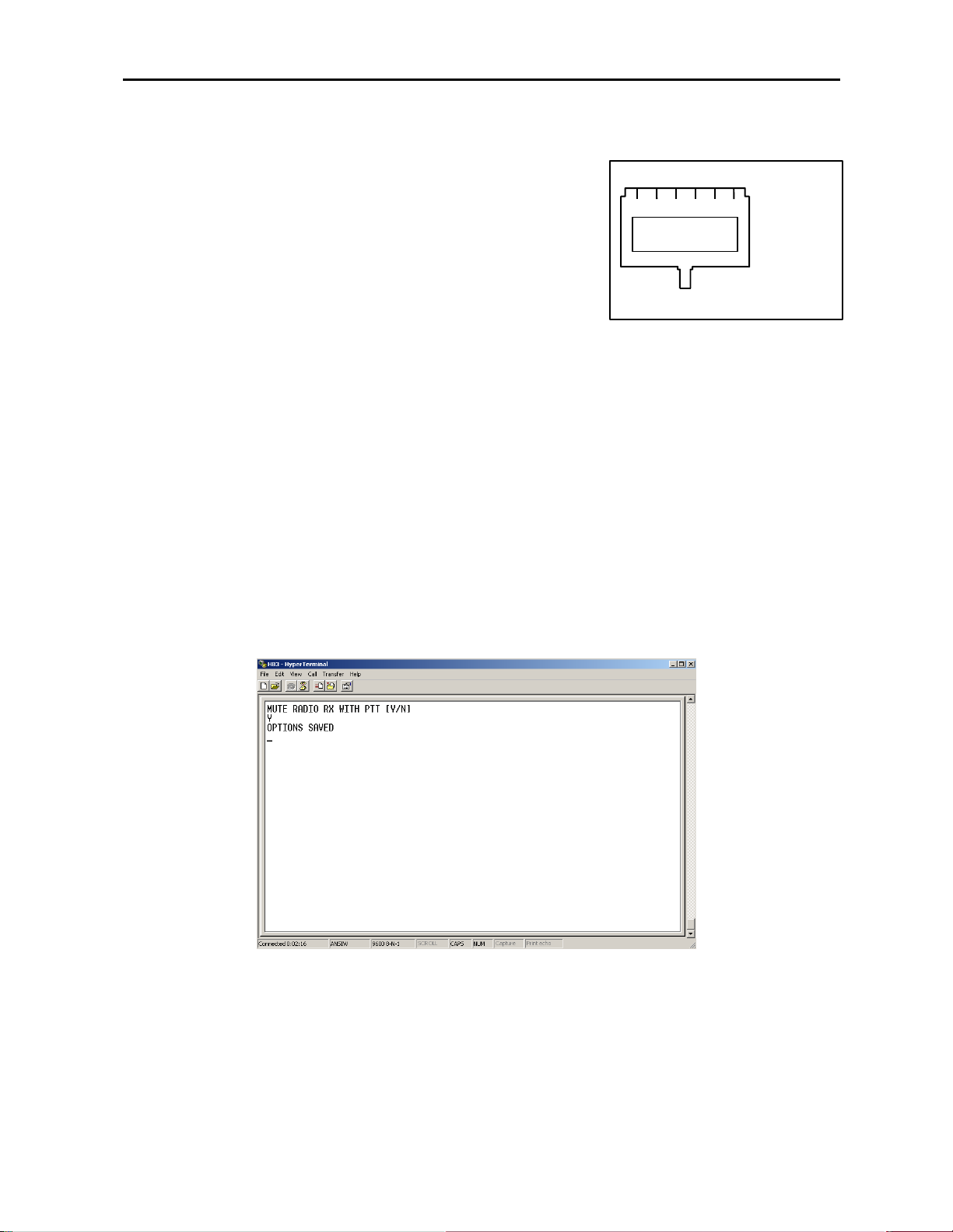
2.2.6 Radio Rx Mute w/PTT – Version 2.1 or Higher
With the release of software Version 2.1, the Windows ® HyperTerminal application may be used
to set, as a programmable option, if radio Rx is muted with PTT. Usually, the radio Rx is muted
when the radio PTT is active. However, full duplex and cell phone Direct Connect applications
require audio (i.e. go ahead tones) to be heard by the user after PTT is pressed.
With the PC connected to the HB3Plus and HyperTerminal running, press “M” on the PC
keyboard. The HB3Plus will respond with “MUTE RADIO RX WITH PTT [Y/N]” as shown in
Figure 3.
1 2 3 4 5 6
Desk Mic Connector
1) GND
2) Mic
3) GND
4) PTT Sw
5) MON Sw
6) +Bias
Figure 3 HyperTerminal Screen
Press “Y” or “N” (upper or lower case), depending on your application. The HB3Plus will save the
selection, check for accuracy and, if saved with no errors, respond with “OPTIONS SAVED”
Reset the HB3Plus.
Page 7
HB-3Plus Headset Adaptor Box 7
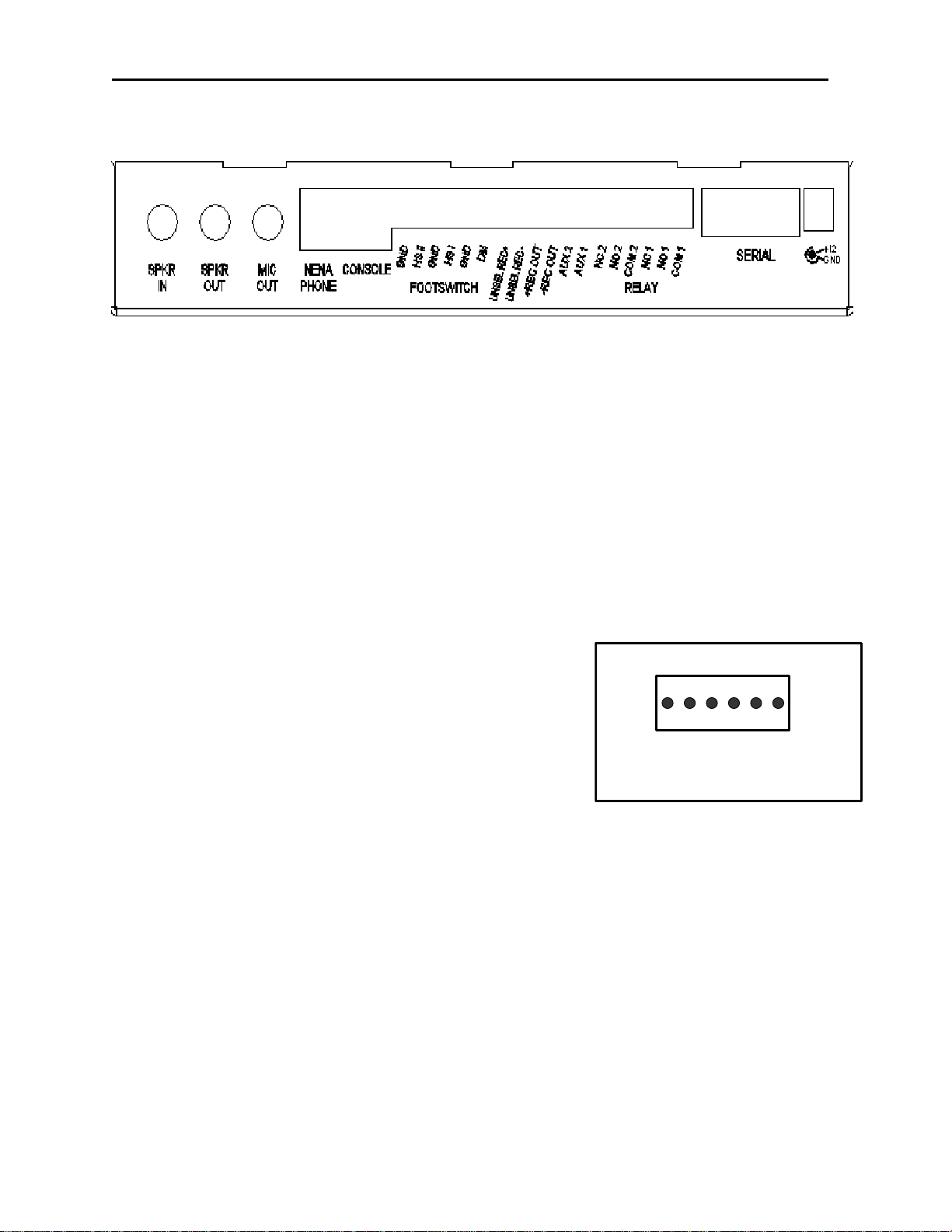
2.3 Rear Panel Connections
Figure 4 HB-3Plus Rear View
2.3.1 Power Supply Connection
The HB-3Plus power requirements are 12 to 16 VDC, 500mA. A wall mounted power supply is
included with the HB-3Plus. Power connection is made via a 2.5mm plug receptacle on the rear
panel of the unit. The positive terminal is the center conductor.
2.3.2 Serial Connection
The serial port is enabled in the HB-3Plus when the PC Mode is set by JMP8 (position A). The
serial port is configured for 9600-baud, 1stop bit, no parity, and DCE connections. A serial cable
is provided for connection to the PC.
In the PC Mode, the HB-3Plus provides the PC with serial data for PTT, Monitor, relay control and
AUX input functions.
2.3.3 Relay Connections
The HB-3Plus provides two Form C relay contacts for
general use. 1 Amp resettable fuses protect both sets of
contacts. Each relay is controlled by the C-Soft application.
Please refer to the C-Soft manual for use of this feature.
A 6-pin screw terminal block provides connection to the
relays. Refer to Figure 5 Relay Connections
NOTE: The Relays Are Operational In The PC Mode
ONLY
1 2 3 4 5 6
1) Relay 1 COM 2) Relay 1 N.O.
3) Relay 1 N.C. 4) Relay 2 COM
5) Relay 2 N.O. 6) Relay 2 N.C.
Figure 5 Relay Connections
2.3.4 AUX IN Connections
The AUX IN connections detect a contact closure to ground and send the information to the CSoft application. Each input is diode protected from voltages above +5VDC.
The two AUX inputs are located at pins 1 and 2 of the middle 6-pin screw terminal block.
Please refer to the C-Soft manual for use of this feature. Refer to Figure 6 Recorder and AUX IN
Connections.
NOTE: The AUX IN Inputs Are Enabled In The PC Mode ONLY
Page 8

8 HB-3Plus Headset Adaptor Box
2.3.5 Recorder Connections
The HB-3Plus provides two balanced recorder outputs. The impedance of each balanced output
is 600 ohms.
Common Recorder Output
The common recorder output sums and amplifies all sources
of audio passing through the HB-3Plus to a balanced output
for a single position recorder capability. Internal jumper JMP9
sets the routing of the UNSELECT audio to the common
recorder output.
1 2 3 4 5 6
A – UNSELECT audio (all audio sources)
B – No UNSELECT audio (all audio sources except
UNSELECT)
The Common Recorder Output is provided at pins 3 and 4 of
the middle 6-pin screw terminal block marked RECORDER
OUT.
UNSELECT Audio Recorder Output
The UNSELECT Audio Recorder Output provides UNSELECT audio to a separate balanced
output. The UNSELECT Recorder Output is provided at pins 5 and 6 of the middle 6-pin screw
terminal block marked UNSEL REC Out.
2.3.6 Footswitch Connections
The HB-3Plus provides separate PTT footswitch inputs for the desk mic, Headset I and Headset
II. The PTT function is activated by a contact closure to ground. Each input is diode protected
from voltages above +5VDC. Pin 6 is a dual function pin providing a GND or +9VDC connection.
Refer to section 2.3.7.
For 6513C desk microphones manufactured before October
2005, the microphone PTT switch gates mic audio. If PTT is
generated from sources other than the desk microphone
PTT switch (i.e. Instant PTT, footswitch or front panel PTT),
TX audio is not passed to the HB3Plus for routing to the
selected line. Refer to Vega Application Note MN-VEGA-13
for microphone rewiring instructions.
1) AUX 1 IN 2) AUX 2 IN
3) Recorder Out 4) Recorder Out
5) UnSel Rec Out 6) UnSel Rec Out
Figure 6 Recorder and AUX IN Connections
1 2 3 4 5 6
1) D e s k Mic IN 2) G ND
3) Headset I IN 4) GND
5) H e a d se t II IN 6 ) GN D/+ 9
Figure 7 Footswitch Connections
2.3.7 +9VDC Output Connection
Pin 6 of the footswitch terminal block is a dual function pin. It may be configured to provide a +9VDC
50mA power output or GND. A resettable fuse protects the +9VDC output. Refer to Figure 7.
JMP7 sets the pin configuration.
A – GND
B – +9VDC@50mA
Page 9

HB-3Plus Headset Adaptor Box 9
2.3.8 PC Sound Card Connections
Three Audio Cables are provided for connection of the HB-3Plus to the PC sound card and
desktop speakers. The desktop speakers MUST be amplified. Refer to Figure 8.
SERIAL
2.3.9 Console Connections
The HB-3Plus connects directly to the handset port of a Vega dispatch console (C-5000, C-1610,
C-1616, C-2000, C-2002, IP1616 and C-6200) from the
Console RJ11 CONSOLE connector when the CONSOLE
MODE is set by JMP8. A 4-pin modular cable is provided for
connection to the console.
The HB-3Plus provides the audio paths for radio Tx from the
headset or desk mic and SELECT audio. System PTT and
SELECT audio routing are also controlled by the HB-3Plus.
SELECT audio is routed to the console speaker when the
Headset Switch in the OFF position or when the NENA
system is off-hook. UNSELECT audio is NOT available to the
HB-3Plus from the console.
NOTE: The Handset Port On The Console Must Be ENABLED.
Refer To The Console Technical Manual For Instructions
Amplified Desktop Speakers
Select Unselect
L
Figure 8 HB-3Plus to PC Connection Diagram
R
SPKR
OUT
SPKR
IN
MIC
OUT
PC with
Soundcard
Mic
Speakers
1 2 3 4
1) TX
2) G round
3) PTT
4) RX
HB3Plus Console Connector
Figure 9 HB-3Plus To Console Connector Pin-out
Page 10
10 HB-3Plus Headset Adaptor Box
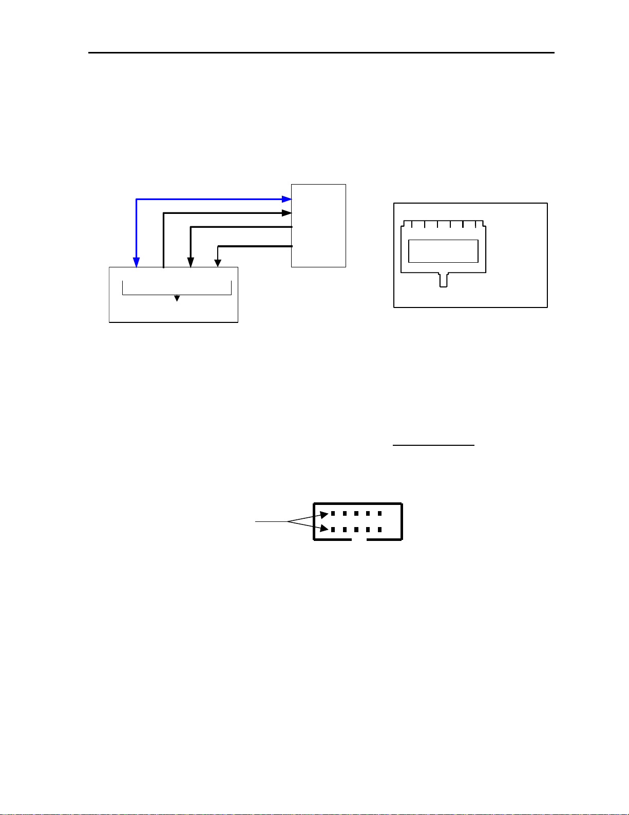
2.3.10 NENA Phone Connections
The HB-3Plus connects to a NENA device from the RJ-12 NENA PHONE connector. The NENA
Tx and RX are balanced 600-ohm audio connections to eliminate DC differences or ground loops
between the systems. The off-hook condition is triggered by a contact closure to ground. The
hook switch input is diode protected from DC voltages above +5VDC.
Refer to Figure 10 for the Wiring diagram and connector pin-out.
6 2 & 5 3 & 4 1
NENA PHONE CONNECTOR
Ground
TX to NENA
RX from NENA
Hook-switch
Figure 10 NENA to HB3Plus Connections and Pinout
2.4 Software Version
2.4.1 Software/Hardware Match Up
Updates to the PCB require the software to include a “Legacy” mode that allow it to operate in
older circuit board layouts. Circuit boards with part number 750728 REV “B” or higher MUST
have a jumper installed across pins 1 and 2 of connector J12. See Figure 11for jumper location.
JUMPER ACROSS
PINS 1 AND 2
J12
Figure 11 HB3Plus Hardware Identification Jumper
NENA
Phone
1 2 3 4 5 6
750728 REV C
# 880125 REV___
1) Hook Switch
2)
3)
4)
5)
6)
NENA Connector
OUT
IN
IN
Out
Ground
2.4.2 Determine The Software Version
The software version of the HB-3Plus may be determined by connecting the HB-3Plus serial port
to a PC with Windows® HyperTerminal running. Set the HyperTerminal parameters to 9600
baud, 1stop bit, and no parity. Place JMP8 in the “A” position to set the PC mode.
Press “V” on the PC keyboard, the HB-3Plus will respond with the software version number (i.e.
VER 1.12).
NOTE: This Feature Is Available On Versions 1.12 Or Higher
Page 11

HB-3Plus Headset Adaptor Box 11
3 Audio Level Adjustments
The HB-3Plus provides five internal adjustments for setting various levels of operation:
• Desk Mic Level
• NENA In
• NENA Out
• Recorder Out
• Recorder Unsel Out
The internal adjustments may be set after the HB-3Plus is mounted. All five adjustments are
accessible from the bottom of the enclosure and do not require the HB-3Plus to be open for
adjustment.
Headset I and II receive volume levels are user adjustable by the SELECT controls on the front
panel.
3.1 Desk Microphone TX Level
The desk microphone level may be adjusted from the DESK MIC LEVEL access point on the
bottom of the enclosure.
The MD-MS electret desk mic has a level adjustment located on the bottom plate of the mic. The
nominal position of this control is mid-range.
3.2 NENA Phone Level
The NENA phone levels may be adjusted from the NENA IN and NENA OUT access points on
the bottom of the enclosure.
3.3 Recorder Level
Each recorder output level (Common Rec order and Unsel Recorder) may be adjusted from the
access points on the bottom of the enclosure.
3.4 Headset Transmit Level
Each headset TX circuit uses a clipper/filter circuit that does not require any adjustment. The level
is designed to match the requirements of the Vega dispatch consoles or the C-Soft application.
Page 12

12 HB-3Plus Headset Adaptor Box
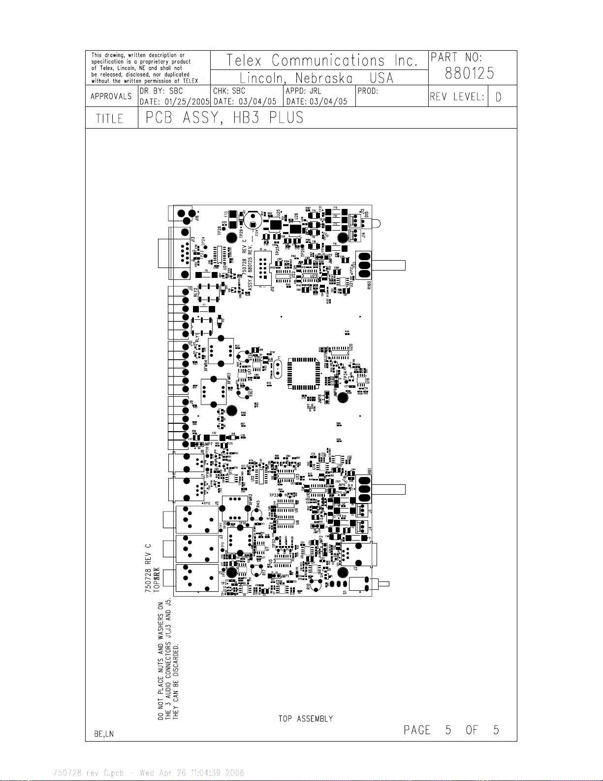
4 Component Location and Parts Lists
Page 13
V
A
A
A
A
A
A
R
A
A
A
A
This drawing, written description or specification Is
a proprietary product of TELEX, Lincoln, NE, and
shall not be released, disclosed, nor duplicated
without the written permission of TELEX.
APPROVALS: DR BY: SBC
DATE: 01/25/2005
DATE; 03/04/05
Telex Communications INC.
Lincoln, Nebraska USA
APPD: JRL
DATE: 03/04/05
PROD:CHK: SBC
PART NO:
REV LEVEL:
880125
D
TITLE:
PCB ASSY, HB3 PLUS
REVISIONS
RE
1 PROTOTYPE
UPDATED REV 1 REMOVED JMP6 AND JMP13
ITEM 59 CHANGE PART NUMBER TO 7302831
ITEM 1 QTY TO 26 ITEM 8 QTY TO 10
ITEM 32 QTY TO 97 ITEM 35 QTY TO 3
DELETED ITEM 46 ITEM 47 QTY TO 10
DDED ITEM 65
DDED ITEM 67
ITEM 53 CHANGED PART NUMBE
ITEM 40 QTY TO 5 ITEM 10 QTY TO 23
B
SHEET 4 UPDATED TO REFLECT CORRECT ORIENTATION OF D13 AND D14
C ITEM 34 QTY TO 96
CHANGE MIC BIAS TO HIGH SIDE BIAS AND DO ROHS CHANGES
D
PCB TO REV C ROHS CHANGES
ITEM 1 QTY TO 24 ITEM 6 QTY TO 21
ITEM 7 QTY TO 20 ITEM 10 QTY TO 23
ITEM 12 QTY TO 0 ITEM 15 QTY TO 4
ITEM 17 QTY TO 8 ITEM 19 QTY TO 11
ITEM 29 QTY TO 7 ITEM 30 QTY TO 7
ITEM 31 QTY TO 20 ITEM 32 QTY TO 94
ITEM 40 QTY TO 3 ITEM 42 QTY TO 0
ITEM 47 QTY TO 10 ITEM 56 CHG PART # QTY TO 2
ITEM 57 QTY TO 0
DDED ITEM 70 QTY TO 1ADDED ITEM 71 QTY TO 2
DDED ITEM 72 QTY TO 1
DESCRIPTION ECO NO DATE
DDED ITEM 66
DDED ITEM 68
DDED ITEM 69
DDED ITEM 69 QTY TO 2
41-000146
41-000174
41-000197
41-000210
41-000361
01/25/05
01/28/05
03/04/05
04/04/05
04/26/05
03/31/06
PPD
SBC
SBC
JRL
JRL
JRL
JRL
LN,BE PAGE 1 OF 5
Page 14

K
NMC0805X7R105K10TRPLP3KF
0
F
F
F
5
r
G
8
c
0
o
e
T
T
e
5
5
e
0
0
A
o
6
6
o
3
x
o
2
.
NRSS102M25V 10X20
NMC0603X7R682K50TRP
NMC0603NPO101J50TRP
NMC0603Y5V104Z25TRPF
MMBD914LT1
MMBD914LT1
154003
MRA4004T3 MRA4004T3G
TVB170SA TVB170SA-L
154003
04611.2
2508056017Y
1761602-3
RN112BPC
04611.2
2508056017Y
RN112BPC
5747844-
5520250-
747844-
520250-3
5520249-2
25.332.3653.1
25.332.3653.1
22-23-2031 22-23-2031
520249-
68000-403LF
68000-403
MMBT3904LT1G
880125
PART NO:
D
REV LEVEL:
PROD:CHK: SBC
Manufacturer Manufacurer's part # Manufacturer's RoHS part #
DESIGNATOR
Nic Components NMC0603X7R102K50TRP NMC0603X7R102K50TRPF
Nic Components NRSS102M25V 10X20
Nic Components NMC0805X7R105K10TRPLP3
Nic Components NMC0603X7R682K50TRP
Nic Components NMC0603NPO101J50TRP
C103 C11
C1 C9 C11 C13 C15 C20 C26 C30 C41 C42 C43
C124
C48 C49 C54 C57 C58 C62 C63 C65 C69 C72
C77 C80 C93
C14 C83
C16 C78
Nic Components NMC0603Y5V104Z25TRP
C19 C28 C52 C76 C86 C88 C100 C104 C106
C108 C111 C112 C113 C115 C116 C125 C36 C50
C51 C92 C102
C2 C4 C10 C17 C21 C25 C29 C34 C40 C44 C47
NO.
Telex PART
Nic Components NMC0603NPO330J50TRP NMC0603NPO330J50TRPF
On Semiconducto
Diodes In
Nic Components NMC0603NPO470J50TRP NMC0603NPO470J50TRPF
Nic Components NTC-T335K25TRB NTC-T335K25TRBF
Nic Components NMC0603X7R222K50TRP NMC0603X7R222K50TRPF
C53 C67 C68 C74 C121 C122 C123 C126 C127
C3 C18 C22 C39 C64 C66 C75 C91 C109 C114
C31 C82
Nic Components NTC-T106K16TRB NTC-T106K16TRBF
Nic Components NMC0603NPO471J50TRP NMC0603NPO471J50TRPF
C24 C32 C33 C45 C46 C55 C56 C87 C89 C90
C94 C96 C98 C99 C101 C105 C107 C117 C118
C119 C120 C37 C38
C5 C6 C7 C8 C12 C23 C27 C35 C59 C60 C61
C70 C71 C73 C79 C84 C95 C97
Dialight 550-3005 550-3005F
F13 Littlefus
D15
F1 F3 F5 F9 F10 F14 F16 F18 Raychem/Tyc
D13 D14 D17 D1
C81 C8
D1 D2 D3 D4 D5 D6 D7 D8 D9 D10 D11 D12 D16
F2 F4 F6 F7 F8 F11 F12 F15 F17 F19 F20 Littlefus
FB1 FB2 Fair-Rit
50808800
mp 103308-1
J13 Tyc
J1 J3 J5 Switchcraft
J12
21-01-028713
J9 J10 J11 Wieland
J8 Tyc
J16 Kycon 16PJ032 KLDX-0202-B
J2 J7 Tyc
J4 J6 J14 J15 Mole
Framatome (FCI)
Connectors
FOR JMP1 JMP2 JMP3 JMP7 JMP8 JMP9
JMP12 Samtec SNT-100-BK-G SNT-100-BK-G
JMP1 JMP2 JMP3 JMP7 JMP8 JMP9 JMP12
Q1 Q2 Q3 Q5 Q6 Q7 Q8 Q9 Q10 Q11 Q12 Q13
Q14 Q15 Q16 Q17 Q18 Q19 Q20 Q21 On Semiconductor MMBT3904LT1
APPD: JRL
DATE; 03/04/05
Lincoln, Nebraska USA
Telex Communications INC.
DATE; 03/04/05
This drawing, written description or specification Is
a proprietary product of TELEX, Lincoln, NE, and
DATE: 01/25/2005
shall not be released, disclosed, nor duplicated
without the written permission of TELEX
APPROVALS: DR BY: SBC
PCB ASSY, HB3 PLUS
TYPE DESCRIPTION SMT or T/H
QTY
NEW
TITLE:
ITEM
2 2 CAP .001UF 0603 50V +/-10% SMT 102881717T
3 1 CAP 1000UF 25V LEADED T/H 51821526
1 24 CAP 1UF 0805 10V +/-10% SMT 102881875T
4 2 CAP 6800PF 0603 50V +/-5% SMT 102881708T
5 2 CAP 100PF 0603 50V +/-5% SMT 723482130T
6 21 CAP 0.1UF 0603 SMT 723489101T
7 20 CAP 47PF 0603 SMT 723482126T
8 10 CAP 3.3UF TANT 10V B(3528) SMT 102877021T
9 2 CAP 2200PF 0603 50V +/-5% SMT 723483107T
10 23 CAP 10uf 16vTANT 3528 B SMT 102877065T
14 13 DIODE MMBD914 SOT-23 SMT 58711000T
11 18 CAP 470PF 0603 50V +/-5% SMT 723482138T
12
13 2 CAP 33PF 0603 SMT 723482124T
16 1 LED RT ANG. LED RED/GRN T/H
17 8 THYRISTOR TVB170SA SMT 710106
15 4 DIODE SMT 4004 1A DIODE (S1G-13) SMT 760621-4
18 1 FUSE FUSE AND HOLDER 3 AMP SMT 710105T
19 11 FUSE F1250T Teccor Fuse SMT 710109T
20 2 FERRITE 0805 FERRITE BEAD SMT 723511T
21 3 CONN 1/4" STEREO JACK RN112BPC T/H
23 1 CONN RT ANG DB9 TH T/H 640149
22 1 CONN HEADER, 10 PIN SHROUDED T/H 650381
24 1 CONN 2.5MM LEADED POWER T/H 59697000
25 2 CONN RJ11 TELCO RECEPT T/H 59946000
26 4 CONN 3 Pin Locking Header T/H 2861870
RT ANGLE 4 PIN HANDSET JACK T/H 640123
27 1 CONN
28 3 CONN 6 PIN RT ANGLE TERMINAL T/H 2862056
30 7 CONN JUMPER CAP 2515001001
29 7 CONN 3 PIN T/H HEADER T/H 8800124519
TRANSISTOR MMBT3904 SMT 54671200T
31 20
LN,BE Page 2 of 5
Page 15

.
r
PT6WV-105A2020 PT6WV-105A2020
s
7
s
s
8
r
s
8
s
5
s
s
5
s
4
s
o
m
0
s
T
4
X
NRC06F3010TR NRC06F3010TRF
NRC06J273TR NRC06J273TRF
NRC06F3323TR NRC06F3323TRF
NRC06F1002TR NRC06F1002TRF
PT6WV-104A2020 PT6WV-104A2020
NRC06ZOTR NRC06ZOTRF
NRC06F4753TR NRC06F4753TRF
NRC06F1003TR NRC06F1003TRF
NRC06J272TR NRC06J272TRF
NRC06J470TR NRC06J470TRF
NRC06F1500TR NRC06F1500TRF
NRC06F1001TR NRC06F1001TRF
7101P4D9AV2BE
7101P4D9AV2BE
LM339DR LM339DR
TLV2374ID TLV2374ID
LM317MDTRKG
MAX3232CSE+
822499-1 3-822516-1
MAX3232CSE
CD4053BMT
CD4053BM
NATL LM317MDTX OR ON SEMI
LM317MDTRK SUGGESTED T&R
ECS-110.5-S-4 ECS-110.5-S-4
D
880125
PART NO:
REV LEVEL:
PROD:CHK: SBC
APPD: JRL
Lincoln, Nebraska USA
DATE; 03/04/05
Manufacturer Manufacurer's part # Manufacturer's RoHS part #
DESIGNATOR
R1 R2 R3 R4 R6 R7 R8 R11 R12 R14 R22 R24
R27 R28 R29 R30 R31 R33 R34 R36 R37 R38
R39 R43 R44 R47 R48 R49 R52 R54 R55 R56
R58 R59 R60 R62 R64 R65 R66 R67 R69 R70
R71 R73 R74 R75 R76 R78 R81 R82 R84 R85
R86 R87 R88 R89 R90 R91 R92 R93 R103 R104
R105 R106 R109 R115 R116 R117 R118 R119
R120 R121 R123 R126 R129 R132 R133 R134
NO.
Telex PART
Nic Component
Pihe
R112 R131 Nic Component
R83 R110 R14
R153 Nic Component
R17 R45 R107 R12
R10 Pihe
R136 R137 R140 R142 R143 R145 R146 R148
R149 R150 R152 R154 R155 R157 R158 R161 Nic Components
R18 R19 R21 R26 R77 R94 R96 R97 R98 R99
Nic Component
Nic Component
Nic Component
R100 R101 R102 R108 R111 R113 R127 R130
R135 R162 R163 R165 R166 R167 R168 R169 Nic Components
R20 Nic Component
R23 R53 R13
R32 R3
R46 R151 Nic Component
R5 R79 R80 R9
Atmel AT89S8253-JC AT89S8253-24JU
R13 R25 R41 R68 R114 R125 R139 R141 R40
R50 Nic Components
RLY1 RLY2 Tyco/Axicom V23026-D1022-B201 1393776-
S1 C&K(ITT CANNON)
U1 U2 U3 U4 U6 U7 U11 U14 U15 U16 U17 U19
U21 Texas Instruments NE5532AD NE5532AD
U18
SOCKET FOR U18 Tyc
U24 Maxi
U12 U22 Texas Instrument
Texas Instrument
ON Semiconductor
U5 U8 U9 U13 U2
XFMR1 XFMR2 XFMR3 XFMR
U25 U26
511552000S U10 U23 Texas Instruments
ECS Inc
ECS Inc 700-9001
Nic Components NRC06J472TR NRC06J472TRF
Y1
TO BE USED WITH Y1
R63
Telex Communications INC.
DATE; 03/04/05
This drawing, written description or specification Is
a proprietary product of TELEX, Lincoln, NE, and
DATE: 01/25/2005
shall not be released, disclosed, nor duplicated
without the written permission of TELEX
APPROVALS: DR BY: SBC
PCB ASSY, HB3 PLUS
TYPE DESCRIPTION SMT or T/H
QTY
NEW
TITLE:
ITEM
34 2 RES 301 OHM 0603 1% SMT 723481146T
35 3 RES 27K 0603 5% SMT 723488273T
33 1 POT 1MEG VERT. ADJ T/H LINEAR T/H 57148413
32 94 RES 10K 0603 1% SMT 723481300T
36 1 RES 332K 0603 100V 1% SMT 723481450T
37 4 POT 100K VERT. ADJ T/H LINEAR T/H 57148410
38 26 RES 0 OHM 0603 5% SMT 723488000T
39 1 RES 475K 0603 1% SMT 723481465T
40 3 RES 100K 0603 1% SMT 723481400T
41 2 RES 2.7K 0603 5% SMT 723488272T
42
43 2 RES 47 OHMS 0603 5% SMT 723488470T
44 4 RES 150 OHMS 0603 1% SMT 723481117T
454647 10 RES 1K 0603 1% SMT 723481200T
48 2 RELAY SMT SPDT 12V RELAY SMT 730142
49 1 SWITCH TOGGLE SPDT PC MNT T/H 2990348
50 13 IC NE-5532 SO-8 DUAL OP Amp SMT 760268T
51 2 IC TLV2374ID QUAD OP AMP SMT
53 1 IC 89S8252 MICROCONTROLLER 5115560001PS
54 1 IC SOCKET PLCC44 SMT 539030044
55 1 IC MAX3232 RS232 DRIVER SO16 SMT 760349S
52 2 IC LM339 QUAD COMPARATOR SMT 59607100T
56 2 IC LM317M SMT 760250T
57
58 5 IC CD4053B ANALOG SWITCH SMT 53266123T
59 4 XFMR 600:600 AUDIO T/H 7302831
60 1 XTAL XTAL 11.0592MHZ HC49 T/H 780196
61 1 INSULATOR MYLAR MS49 59225500
62 1 PCB PRINTED CIRCUIT BOARD 750728
63 0 SCH SCHEMATIC 770952
LN,BE Page 3 of 5
64 1 RES 4.7K 0603 5% SMT 723488472T
Page 16
.
D
4
R
4
880125
Manufacturer Manufacurer's part # Manufacturer's RoHS part #
Nic Components NRC06F2001TR NRC06F2001TRF
Nic Components NRC06F2211TR NRC06F2211TRF
Nic Components NRC06F4752TR NRC06F4752TRF
Nic Components NRC06F1503TR NRC06F1503TRF
Nic Components NRC06F3011TR NRC06F3011TRF
On Semiconductor MMBT3906LT1 MMBT3906LT1G
Nic Components NRC06J562TR NRC06J562TRF
Nic Components NRC10F7151TR NRC10F7151TRF
PART NO:
REV LEVEL:
PROD:CHK: SBC
APPD: JRL
DATE; 03/04/05
Lincoln, Nebraska USA
Telex Communications INC.
DATE; 03/04/05
DATE: 01/25/2005
This drawing, written description or specification Is
a proprietary product of TELEX, Lincoln, NE, and
shall not be released, disclosed, nor duplicated
without the written permission of TELEX
APPROVALS: DR BY: SBC
R9
R15 R16 R122 R12
DESIGNATOR
R72
R156
Q4 Q22
R51
R42
R57 R14
NO.
Telex PART
PCB ASSY, HB3 PLUS
MMBT3906 SMT 54716200
TYPE DESCRIPTION SMT or T/H
QTY
NEW
ITEM
67 1 RES 2.21K 0603 1% SMT 723481233T
68 1 RES 47.5K 0603 1% SMT 723481365T
69 2 TRANSISTO
TITLE:
66 4 RES 18.2K 0603 1% SMT 723481229T
65 1 RES 5.6K 0603 5% SMT 723488562T
72 1 RES 3.01K 0603 1% SMT 723481246T
70 1 RES 6.98K SMT 102515281T
71 2 RES 150K 0603 1% SMT 723481417T
LN,BE Page 4 of 5
Page 17
Page 18

HB-3Plus Headset Adaptor Box 13
5 Warranty, Service, Repair, and Comments:
Important!
Be sure the exact return address and a description of the problem or work to be
done are enclosed with your equipment
Warranty (Limited)
All Telex Communications, Vega Signaling products are guaranteed against malfunction due to
defects in materials and workmanship for three years, beginning at the date of original purchase.
If such a malfunction occurs, the product will be repaired or replaced (at our option) without
charge during the three-year period, if delivered to the Telex factory. Warranty does not extend to
damage due to improper repairs, finish or appearance items, or malfunction due to abuse or
operation under other than the specified conditions, nor does it extend to incidental or
consequential damages. Some states do not allow the exclusion or limitation of incidental or
consequential damages, so the above limitation may not apply to you. This warranty gives the
customer specific legal rights, and there may be other rights which vary from state to state.
Factory Service Center
TELEX Communications, Inc.
Vega Signaling Products
8601 East Cornhusker Highway, Lincoln, Nebraska, 68507
Phone: (800) 553-5992 Fax: (402) 467-3279
E-mail: vega@telex.com
, Web: www.vega-signaling.com
.
Claims
No liability will be accepted for damages directly or indirectly arising from the use of our materials or from
any other causes. Our liability shall be expressly limited to replacement or repair of defective materials.
Suggestions or Comments
We would appreciate your input. Please send us your suggestions or comments concerning this manual,
by fax (402-467-3279) or e-mail them to
Technical Support
Technical support is available by calling 800-898-6723 or emailing; awttechsupport@us.telex.com
: vega@telex.com
Visit our web site at www.vega-signaling.com
Page 19

6 HB-3Plus Specifications
Operating Temperature Range: 0 to 55°C for full specifications
Power Requirements: +12 to +16 VDC, semi-regulated, 500ma.
Serial Port: 9600-8-N-1 DCE Configuration
Relay Contact Ratings: 1A 125Vac - Form C Contacts
+9VDC Output: 50mA
Audio Distortion: 2% THD maximum
Frequency Response: ±1.5 dB, 300 to 3000 Hz
NENA Input/Output Impedance: 600Ω nominal
Dimensions: 11” W (28CM) x 5.63” D (14.3CM) x 1.75” H (4.4CM)
TELEX Communications, Inc.
Vega Signaling Products
8601 East Cornhusker Highway, Lincoln, Nebraska, 68507
Phone: (800) 752-7560 Fax: (402) 467-3279
E-mail: vega@telex.com
, Web: www.vega-signaling.com
 Loading...