

Page 1
Supple
mentary instructions
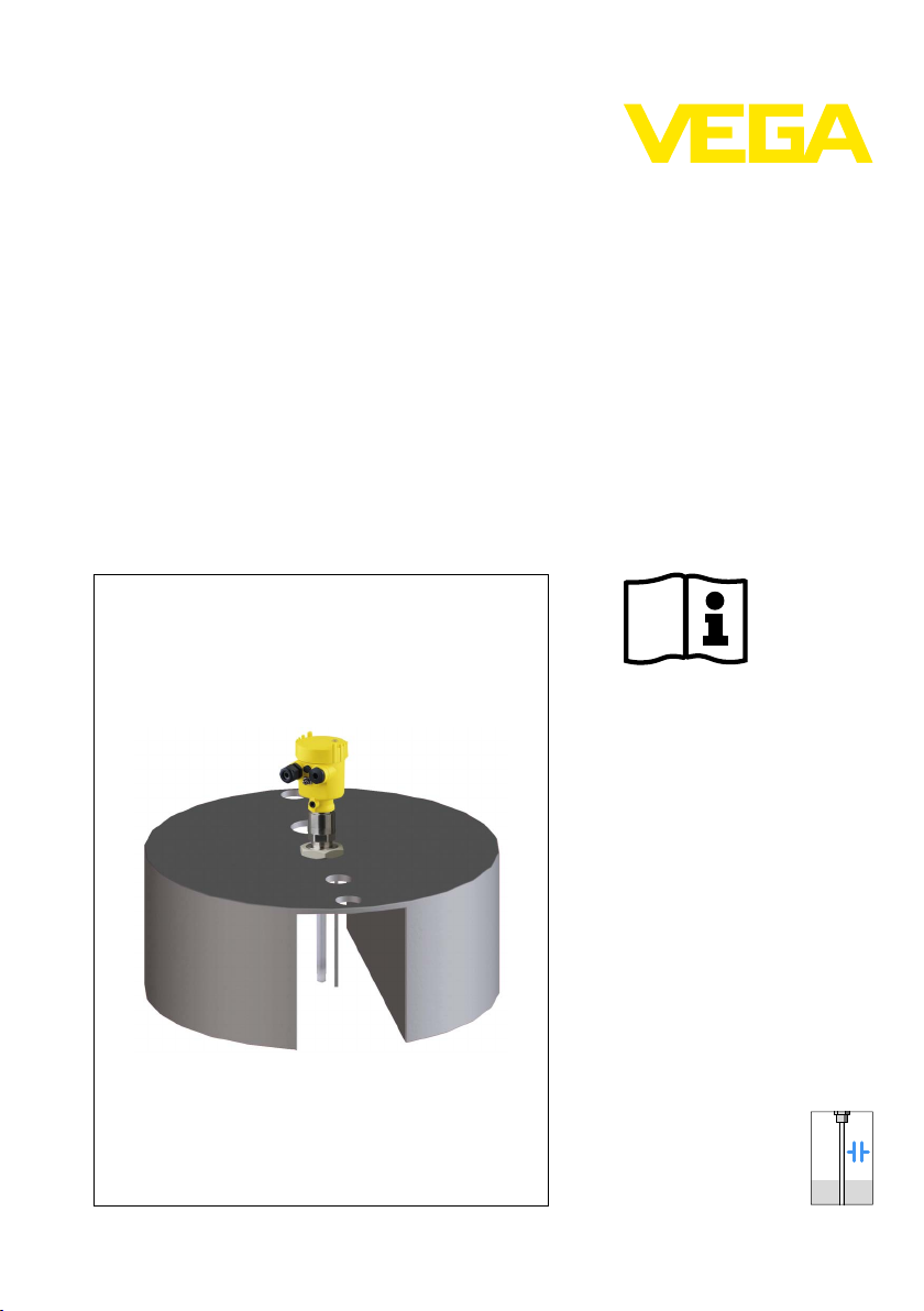
Float for oil/water
for VEGACAP 63
detection
Document ID:
31595
Capacitive
Page 2

1 Conte
nts
Conten
1 About this document
2 For your safety
3 Product description
4 Mounting
5 Connect the sensor
6 Setup
7 Maintenance
ts
1.1 Function. . . . . . . . . . . . . . . . . . . . . . . . . . . . . . . . . .
1.2 Target group . . . . . . . . . . . . . . . . . . . . . . . . . . . . . .
1.3 Symbolism used . . . . . . . . . . . . . . . . . . . . . . . . . . . .
2.1 Authorised personnel . . . . . . . . . . . . . . . . . . . . . . . .
2.2 Appropriate use . . . . . . . . . . . . . . . . . . . . . . . . . . . .
2.3 Environmental instructions. . . . . . . . . . . . . . . . . . . . .
3.1 Structure . . . . . . . . . . . . . . . . . . . . . . . . . . . . . . . . .
3.2 Principle of operation . . . . . . . . . . . . . . . . . . . . . . . .
3.3 Storage and transport . . . . . . . . . . . . . . . . . . . . . . .
4.1 General instructions . . . . . . . . . . . . . . . . . . . . . . . . .
5.1 Preparing the connection . . . . . . . . . . . . . . . . . . . . .
5.2 Connection procedure. . . . . . . . . . . . . . . . . . . . . . . .
6.1 Setup. . . . . . . . . . . . . . . . . . . . . . . . . . . . . . . . . . . .
7.1 Instrument repair . . . . . . . . . . . . . . . . . . . . . . . . . . .
3
3
3
4
4
4
5
5
6
7
8
8
9
11
8 Dismounting
8.1 Dismounting steps . . . . . . . . . . . . . . . . . . . . . . . . . .
8.2 Disposal . . . . . . . . . . . . . . . . . . . . . . . . . . . . . . . . .
9 Supplement
9.1 Technical data . . . . . . . . . . . . . . . . . . . . . . . . . . . . .
9.2 Dimensions . . . . . . . . . . . . . . . . . . . . . . . . . . . . . . .
2 Float
12
12
13
14
31595-EN-100604
for oil/water detection • for VEGACAP 63
Page 3

out this document
1 Ab
1 Abou
t this document
1.1 Function
This supplementary manual, together with the attached operating
instructions manual, has all the information you need for quick setup
and safe operation. Please read this manual before you start setup.
1.2 Target group
This operating instructions manual is directed to trained qualified
personnel. The contents of this manual should be made available to
these personnel and put into practice by them.
1.3 Symbolism used
Inform
ation, tip, note
This symbol indicates helpful additional information.
Cauti
on: If this warning is ignored, faults or malfunctions can
result.
Warning: If this warning is ignored, injury to persons and/or serious
damage to the instrument can result.
Danger: If this warning is ignored, serious injury to persons and/or
destruction of the instrument can result.
applications
Ex
This symbol indicates special instructions for Ex applications.
31595-EN-100604
Float
l List
The dot set in front indicates a list with no implied sequence.
à Action
This arrow indicates a single action.
1 Sequence
Numbers set in front indicate successive steps in a procedure.
for oil/water detection • for VEGACAP 63 3
Page 4

2 For
your safety
or your safety
2 F
2.1 Authorised personnel
All operations described in this operating instructions manual must be
carried out only by trained specialist personnel authorised by the plant
operator.
During work on and with the device the required personal protective
equipment must always be worn.
2.2 Appropriate use
The float for oil/water detection is part of a sensor. It is used for
detection of light liquids on water.
2.3 Environmental instructions
Protection of the environment is one of our most important duties. That
is why we have introduced an environment management system with
the goal of continuously improving company environmental protection.
The environment management system is certified according to DIN
EN ISO 14001.
Please help us fulfil this obligation by observing the environmental
instructions in this manual:
l Chapter "Storage and transport"
l Chapter "Disposal"
4 Float
31595-EN-100604
for oil/water detection • for VEGACAP 63
Page 5
1
2
3
6
4 5
3 Produc
t description
Scope of delivery
Constituent parts
3 Produc
t description
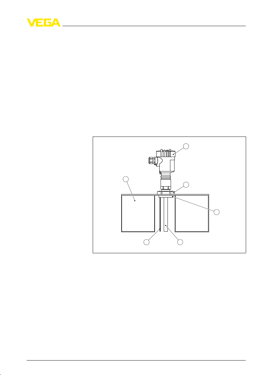
3.1 Structure
The scope of delivery encompasses:
l Floating body for a point level sensor
l Nut G1½ (plastic)
l Adapter with pin
l Ground rod
l Documentation
- This supplementary operating instructions
The instrument version "Point level sensor with float" consists of a float
and the point level sensor.
Application area
31595-EN-100604
for oil/water detection • for VEGACAP 63 5
Float
Fig. 1: Components
1 Probe (mounted in the centre)
2 Nut (plastic)
3 Adapter (316L) with pin
4 Electrode
5 Ground electrode (screwed into the adapter)
6 Float
3.2 Principle of operation
of the float probe
The float is suitable for the following plics
l VEGACAP 63
®
sensors:
Page 6

1
2
4
3
3 P roduc
t description
Functional principle
The probe detects non-conductive light liquids (< 1 kg/dm³) on water,
e.g. in water or oil separating basins.
Fig. 2: Measuring
1 Cable holder for relief
2 Inlet - Water/Oil mixture
3 Oil layer
4 Water
system for oil/water detection
The measuring system floats on the water and due to the own weight
the electrode of the probe immerses up to a certain depth.
If there is e.g. oil on the water surface, the measuring system floats.
The immersion depth of the electrode in water reduces. Hence the
capacitance of the probe changes. The capacitance change is
converted into a switching command.
An oil layer can be already detected from a thickness of 4 mm.
3.3 Storage and transport
Packaging
Storage and transport
temperature
6 Float
Your instrument was protected by packaging during transport. Its
capacity to handle normal loads during transport is assured by a test
according to DIN EN 24180.
The packaging of standard instruments consists of environmentfriendly, recyclable cardboard. For special versions, PE foam or PE foil
is also used. Dispose of the packaging material via specialised
recycling companies.
l Storage and transport temperature see chapter "Supplement -
Technical data - Ambient conditions"
l Relative humidity 20 … 85 %
31595-EN-100604
for oil/water detection • for VEGACAP 63
Page 7

4 M
ounting
Guidance
4 Moun
ting
4.1 General instructions
To prevent the float from touching the vessel wall, it can be guided
vertically.
Use two thin vertical rods or two vertically strained wires at a distance
of 306 mm (12 in) which you lead through the holes in the float plate.
Connection cable
Product movements
Static charges
31595-EN-100604
for oil/water detection • for VEGACAP 63 7
Float
Fig. 3: Guidance
The connection cable can influence the float position of the measuring
system and therefore adulterate the measuring result.
If possible, use a light, flexible connection cable and fasten the cable
with a cable holder. In case of considerable height differences of the
float, you should use a light helix cable.
Product movements can influence the measurement. In this case, use
a signal conditioning instrument with adjustable damping to avoid
fluctuations of the measured value.
There is a danger of static charging on the plastic floating body.
Avoid friction
No dry cleaning
Do not mount in areas with flowing, non-conductive products
of the float
Page 8

5 Conn
ect the sensor
5 Conn
ect the sensor
5.1 Preparing the connection
Follow the instructions in the operating instructions manual of the
sensor.
Th
e connection cable can influence the floating position of the
measuring system. For this reason, use a light, flexible connection
cable and fasten the cable on a cable holder.
5.2 Connection procedure
The electrical connection is described in the operating instructions of
the sensor.
8 Float
31595-EN-100604
for oil/water detection • for VEGACAP 63
Page 9

0 10
5
521
on
1 2 43
5 6 7 8
9 10 11 12 13 14
on
min.
!
VEGATOR 621EX
0 10
5
1
2
6 Setup
6 Setup
6.1 Setup
is carried out according to the operating instructions manual of
Setup
the respective sensor.
Make sure that the measuring system is in the water for setup.
Ti
p:
If setup is not possible in the original vessel, then fill a suitable vessel
(ø approx. 400 mm, height approx. 150 mm) with water and place the
measuring system with float inside the vessel. The measuring result
can be transferred to the original vessel.
Proceed as follows:
1 Connect probe and signal conditioning instrument
2 Switch on power supply
3 Turn the A/B switch on the signal conditioning instrument to
position B
The relay deenergizes if an oil layer is detected (safe condition)
31595-EN-100604
Float
Fig. 4: Suitable
1 Potentiometer
2 Relay control lamp
signal conditioning instruments
4 Set potentiometer (1) to 0. The relay control lamp (2) lights.
5 Turn t he potentiometer (1) slowly clockwise until the relay control
lamp (2) extinguishes.
for oil/water detection • for VEGACAP 63 9
6 Turn the potentiometer (1) very slowly anticlockwise until the relay
control lamp (2) lights.
Page 10

A
C
1
2
B
6 Setup
e the measuring system is set very sensitively. An of oil layer
Henc
of 3 - 4 mm is sufficient to switch the relay.
Information:
To make the measuring system less sensitive, you have to turn the
potentiometer anticlockwise.
The more the potentiometer is turned back, the higher the light liquid
layer has to be to switch the relay.
We recommend connecting the level switch in such a way that the
switching circuit is open when there is a level signal, line break or
failure (safe condition).
An open switch symbol corresponds hence in the following drawing to
the detection of a liquid.
Fig. 5: Switching
A No liquid present
B Water
C Oil layer on water
1 Liquid level water
2 Liquid level oil > 4 mm (> 0.157 in)
status of the measuring system
10 Float
31595-EN-100604
for oil/water detection • for VEGACAP 63
Page 11

7 M
aintenance
7 Maint
enance
7.1 Instrument repair
If a repair of the instrument is necessary, please proceed as follows:
You can download a return form (23 KB) from our Internet homepage
www.vega.com
form".
By doing this you help us carry out the repair quickly and without
having to call back for needed information.
l Print and fill out one form per instrument
l Clean the instrument and pack it damage-proof
l Attach the completed form and probably a safety data sheet to the
instrument
l Send the instrument to the address of the agency serving you. In
Germany, send it to the company headquarters in Schiltach.
under: "Downloads - Forms and certificates - Repair
31595-EN-100604
Float
for oil/water detection • for VEGACAP 63 11
Page 12

8 Dismoun
ting
8 Dismou
nting
8.1 Dismounting steps
Note chapter "Mounting" and carry out the described steps in reverse
order.
8.2 Disposal
The instrument consists of materials which can be recycled by
specialised recycling companies. We have purposely designed the
electronic modules to be easily separable. Mark the instrument as
scrap and dispose of it according to national government regulations
(e.g. in Germany according to electronic scrap ordinance).
Materials: see chapter "Technical data"
If you have no way to dispose of the old instrument properly, please
contact us concerning return and disposal.
12 Float
31595-EN-100604
for oil/water detection • for VEGACAP 63
Page 13

9 Sup
plement
9 Supp
lement
9.1 Technical data
Technical data
Following you find all data deviating from the standard instrument. All other technical data are
specified in the operating instruction of the respective sensor.
General data
Material 316L corresponds to 1.4404 or 1.4435
Materials, wetted parts
- Float PVC
- Nut PPH
- Adapter 316L
- Ground rod 316L
Weights
- Float approx. 2400 g (85 oz)
Suitable point level sensor - VEGACAP 63
- Order length L - Point level sensor 160 mm
- Housing material Plastic
- Electronics version Two-wire electronics (Z)
- Process fitting G ¾ A
Suitable signal conditioning instruments
VEGATOR 521, 621
Process conditions
Process temperature -30 … +60 °C (-22 … +140 °F)
Approvals
The floating body can be used in Ex area zone 1 (ATEX II 2G).
There is a danger of static charging on the plastic floating body.
- Avoid friction
- No dry cleaning
- Do not mount in areas with flowing,
non-conductive products
31595-EN-100604
for oil/water detection • for VEGACAP 63 13
Float
Page 14

5 mm
(0.2")
80 mm
(3.15")
ø 350 mm
(13.78")
306 mm
(12.05")
L
ø 49 mm
(1.93")
ø 27 mm
(1.06")
100 mm
(3.94")
62,5 mm
(2.46")
ø 49 mm
(1.93")
150 mm
(5.91")
ø 25 mm
(0.98")
ø 25 mm
(0.98")
9 Suppl
9.2 D
ement
imensions
Measuring system for oil/water detection
Fig. 6: Measuring
L Order length of the VEGACAP 63 level sensor (L = 160 mm)
system for oil/water detection with VEGACAP 63 point level sensor
14 Float
31595-EN-100604
for oil/water detection • for VEGACAP 63
Page 15

9 Sup
plement
31595-EN-100604
Float
for oil/water detection • for VEGACAP 63 15
Page 16

VEGA Grieshaber KG
ISO 9001
Am Hohenstein 113
77761 Schiltach
Germany
Phone +49 7836 50-0
Fax +49 7836 50-201
E-mail: info@de.vega.com
www.vega.com
Printing date:
statements concerning scope of delivery, application,
All
practical use and operating conditions of the sensors and
processing systems correspond to the information avail-
able at the time of printing.
© VEGA Grieshaber KG, Schiltach/Germany 2010
Subject to change without prior notice 31595-EN-100604
 Loading...