

Page 1
Ope
rating Instructions
VEGABOX 02
Document ID:
32798
Proc
ess pressure/
Hydrostatic
Page 2

Contents
Conten
1 About this document
2 For your safety
3 Product description
4 Mounting
5 Connecting to power supply
6 Set up
ts
1.1 Function. . . . . . . . . . . . . . . . . . . . . . . . . . . . . . . . . .
1.2 Target group . . . . . . . . . . . . . . . . . . . . . . . . . . . . . .
1.3 Symbolism used . . . . . . . . . . . . . . . . . . . . . . . . . . . .
2.1 Authorised personnel . . . . . . . . . . . . . . . . . . . . . . . .
2.2 Appropriate use . . . . . . . . . . . . . . . . . . . . . . . . . . . .
2.3 Warning about incorrect use . . . . . . . . . . . . . . . . . . .
2.4 General safety instructions . . . . . . . . . . . . . . . . . . . .
2.5 Safety instructions for Ex areas . . . . . . . . . . . . . . . . .
2.6 Environmental instructions. . . . . . . . . . . . . . . . . . . . .
3.1 Configuration . . . . . . . . . . . . . . . . . . . . . . . . . . . . . .
3.2 Principle of operation . . . . . . . . . . . . . . . . . . . . . . . .
3.3 Packaging, transport and storage . . . . . . . . . . . . . . .
4.1 General instructions . . . . . . . . . . . . . . . . . . . . . . . . .
4.2 Instructions for installation . . . . . . . . . . . . . . . . . . . . .
5.1 Preparing the connection . . . . . . . . . . . . . . . . . . . . .
5.2 Connection procedure. . . . . . . . . . . . . . . . . . . . . . . .
5.3 Wiring plan. . . . . . . . . . . . . . . . . . . . . . . . . . . . . . . .
6.1 Setup steps, pressure transmitter . . . . . . . . . . . . . . .
6.2 Setup steps, temperature transmitter . . . . . . . . . . . . .
4
4
4
5
5
5
5
5
6
7
7
8
9
9
10
11
12
15
15
7 Maintenance and fault rectification
7.1 Maintenance . . . . . . . . . . . . . . . . . . . . . . . . . . . . . .
7.2 Instrument repair . . . . . . . . . . . . . . . . . . . . . . . . . . .
8 Dismounting
8.1 Dismounting steps . . . . . . . . . . . . . . . . . . . . . . . . . .
8.2 Disposal . . . . . . . . . . . . . . . . . . . . . . . . . . . . . . . . .
9 Supplement
9.1 Technical data . . . . . . . . . . . . . . . . . . . . . . . . . . . . .
9.2 Dimensions . . . . . . . . . . . . . . . . . . . . . . . . . . . . . . .
2 VE
16
16
17
17
18
20
32798-EN-120820
GABOX 02
Page 3

Contents
plementary documentation
Sup
p:
Ti
For safe use and operation of the instrument, the operating instructions
manual of the respective pressure transmitter is also required.
Editing status: 2012-08-02
32798-EN-120820
VEGABOX 02 3
Page 4
1 Abou
t this document
1 Abou
t this document
1.1 Function
This operating instructions manual provides all the information you
need for mounting, connection and setup as well as important
instructions for maintenance and fault rectification. Please read this
information before putting the instrument into operation and keep this
manual accessible in the immediate vicinity of the device.
1.2 Target group
This operating instructions manual is directed to trained qualified
personnel. The contents of this manual should be made available to
these personnel and put into practice by them.
1.3 Symbolism used
Inform
ation, tip, note
This symbol indicates helpful additional information.
Cauti
on: If this warning is ignored, faults or malfunctions can
result.
Warning: If this warning is ignored, injury to persons and/or serious
damage to the instrument can result.
Danger: If this warning is ignored, serious injury to persons and/or
destruction of the instrument can result.
applications
Ex
This symbol indicates special instructions for Ex applications.
l List
The dot set in front indicates a list with no implied sequence.
à Action
Th
is arrow indicates a single action.
1 Sequence
Numbers set in front indicate successive steps in a procedure.
Battery
This symbol indicates special information about the disposal of
batteries and accumulators.
4 VE
disposal
32798-EN-120820
GABOX 02
Page 5

your safety
2 For
or your safety
2 F
2.1 Authorised personnel
All operations described in this operating instructions manual must be
carried out only by trained specialist personnel authorised by the plant
operator.
During work on and with the device the required personal protective
equipment must always be worn.
2.2 Appropriate use
The VEGABOX 02 is a breather housing for pressure transmitters
VEGAWELL 52 and VEGAWELL 72.
The optionally integrated temperature transmitter is used for con-
nection to the resistance thermometer Pt 100, which is dependent on
the version integrated in the pressure transmitters.
2.3 Warning about incorrect use
Inappropriate or incorrect use of the instrument can give rise to
application-specific hazards, e.g. vessel overfill or damage to system
components through incorrect mounting or adjustment.
2.4 General safety instructions
This is a high-tech instrument requiring the strict observance of
standard regulations and guidelines. The user must take note of the
safety instructions in this operating instructions manual, the countryspecific installation standards as well as all prevailing safety
regulations and accident prevention rules.
The instrument must only be operated in a technically flawless and
reliable condition. The operator is responsible for trouble-free
operation of the instrument.
During the entire duration of use, the user is obliged to determine the
compliance of the necessary occupational safety measures with the
current valid rules and regulations and also take note of new
regulations.
2.5 Safety instructions for Ex areas
Please note the Ex-specific safety information for installation and
operation in Ex areas. These safety instructions are part of the
operating instructions manual and come with the Ex-approved
instruments.
32798-EN-120820
VEGABOX 02 5
Page 6

2 For
your safety
2.6 Envi
Protection of the environment is one of our most important duties. That
is why we have introduced an environment management system with
the goal of continuously improving company environmental protection.
The environment management system is certified according to DIN
EN ISO 14001.
Please help us fulfil this obligation by observing the environmental
instructions in this manual:
l Chapter "Packaging, transport and storage"
l Chapter "Disposal"
ronmental instructions
6 VE
32798-EN-120820
GABOX 02
Page 7
2
1
3
3 Produc
t description
pe of delivery
Sco
Constituent parts
3 Produc
t description
3.1 Configuration
The scope of delivery encompasses:
l VEGABOX 02 breather housing
l Protective cover (optional)
l Documentation
- this operating instructions manual
The VEGABOX 02 consists of the components:
l Breather housing
l Temperature transmitter for Pt 100 (optionally integrated)
l Protective cover (optional)
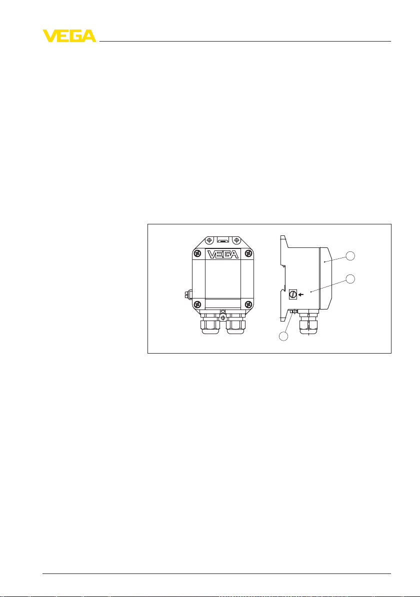
Fig. 1: VEGABOX 02
1 Housing
2 Housing
3 Breather facility
cover
3.2 Principle of operation
Appli
cation area
Voltage supply
32798-EN-120820
VEGABOX 02 7
VEGABOX 02 is a breather housing for pressure transmitters with
connection cable with integrated capillary lines. It is particularly
suitable for the following VEGA pressure transmitters:
l VEGAWELL 52 - 4 … 20 mA
l VEGAWELL 52 - 4 … 20 mA
l VEGAWELL 52 - 4 … 20 mA/HART Pt 100
l VEGAWELL 72 - 4 … 20 mA
l VEGAWELL 72 - 4 … 20 mA/HART
l VEGAWELL 72 - 4 … 20 mA/HART Pt 100
The connection cable of the sensor as well as the power supply cable
are connected to the VEGABOX 02. Connection is carried out via
screw terminals.
Page 8

3 Produc
t description
Packag
ing
Transport
Transport inspection
Storage
Storage and transport
temp
erature
3.3 Pack
aging, transport and storage
Your instrument was protected by packaging during transport. Its
capacity to handle normal loads during transport is assured by a test
according to DIN EN 24180.
The packaging of standard instruments consists of environmentfriendly, recyclable cardboard. For special versions, PE foam or PE foil
is also used. Dispose of the packaging material via specialised
recycling companies.
Transport must be carried out under consideration of the notes on the
transport packaging. Nonobservance of these instructions can cause
damage to the device.
The delivery must be checked for completeness and possible transit
damage immediately at receipt. Ascertained transit damage or
concealed defects must be appropriately dealt with.
Up to the time of installation, the packages must be left closed and
stored according to the orientation and storage markings on the
outside.
Unless otherwise indicated, the packages must be stored only under
the following conditions:
l Not in the open
l Dry and dust free
l Not exposed to corrosive media
l Protected against solar radiation
l Avoiding mechanical shock and vibration
l Storage and transport temperature see chapter "Supplement -
Technical data - Ambient conditions"
l Relative humidity 20 … 85 %
8 VE
32798-EN-120820
GABOX 02
Page 9

4 M
ounting
Installation position
Moisture
Mounting versions
4 Moun
ting
4.1 General instructions
VEGABOX 02 can be mounted in any position. However, vertical
mounting is recommended. This avoids pollution of the breather facility
and moisture penetration.
Note:
Th
ere must be the same atmospheric pressure on the breather facility
as on the measuring point. Otherwise the measured value can be
adulterated.
Use the recommended cables (see chapter "Connecting to power
supply") and tighten the cable gland.
4.2 Instructions for installation
VEGABOX 02 can be mounted as follows:
l on carrier rail 35 x 7.5 according to EN 50022
l on mounting plate or on the wall
32798-EN-120820
VEGABOX 02 9
Page 10

ecting to power supply
5 Conn
Note
safety instructions
Take note of safety instructions
for Ex applications
Selec
t connection cable
5 Conn
ecting to power supply
5.1 Preparing the connection
Always keep in mind the following safety instructions:
l Connect only in the complete absence of line voltage
In
hazardous areas you must take note of the respective regulations,
conformity and type approval certificates of the sensors and power
supply units.
The instrument is connected with standard two-wire cable without
screen. If electromagnetic interference is expected which is above the
test values of EN 61326 for industrial areas, screened cable should be
used.
Use cable with round cross-section. A cable outer diameter of 5 … 9 mm
(0.2 … 0.35 in) ensures the seal effect of the cable gland. If you are
using cable with a different diameter or cross-section, exchange the
seal or use a suitable cable gland.
When the optionally integrated temperature transmitter is also
connected, a four-wire cable is required; when an external temperature transmitter is connected, a six-wire cable is required.
10 VE
32798-EN-120820
GABOX 02
Page 11

ecting to power supply
5 Conn
of VEGABOX 02 to the sensor
Select connection cable for Ex
applications
Cable screening and
groun
ding
Cable screening and
groun
ding for Ex appli-
cations
Fig. 2: Connection
ke note of the corresponding installation regulations for Ex
Ta
applications.
If screened cable is necessary, connect the cable screen on both ends
to ground potential. In the VEGABOX 02, the screen must be
connected directly to the internal ground terminal. The ground terminal
on the outside of the housing must be connected to the potential
equalisation (low impedance).
If potential equalisation currents are expected, the connection on the
processing side must be made via a ceramic capacitor (e. g. 1 nF,
1500 V). The low frequency potential equalisation currents are thus
suppressed, but the protective effect against high frequency interference signals remains.
In Ex applications, one-sided grounding on the sensor is recommended, see EN 60079-14.
5.2 Connection procedure
Proceed as follows:
32798-EN-120820
VEGABOX 02 11
Page 12

1
2
–
+
1 2 3 4 5 6
1 2 3 4 5 6
ecting to power supply
5 Conn
VEGAWELL 52 -, 72 - 4 …
20 mA
1 Snap VE
GABOX 02 onto the carrier rail or screw it to the mounting
plate
2 Loosen the cover screws and remove the cover
3 Insert the sensor cable into VEGABOX 02 through the cable entry
4 Loosen the screws with a screwdriver
5 Insert the wire ends into the open terminals according to the wiring
plan
6 Tighten the screws with a screwdriver
7 Check the hold of the wires in the terminals by lightly pulling on
them
8 Tighten the compression nut of the cable entry. The seal ring must
completely encircle the cable
9 Connect the supply cable according to steps 3 to 8
10 Screw the housing cover back on
The electrical connection is hence finished.
5.3 Wiring plan
Fig. 3: Terminal
1 To power supply or the processing system
2 Shielding
Wire number Wire colour/Polarity VEGABOX 02 terminal
1 brown (+) 1
2 blue (-) 2
1)
Connect
of the housing as prescribed. The two terminals are galvanically connected.
12 VE
assignment VEGABOX 02
1)
screen
to ground terminal. Connect ground terminal on the outside
32798-EN-120820
GABOX 02
Page 13

1
2
+
1 2 3 4 5 6
1 2 3 4 5 6
1
2
1
3
–
+
1 2 3 4 5 6
1 2 3 4 5 6
VEGAWELL 72 - VEGABAR 74, 75 - 4 … 20 mA/
HART
ecting to power supply
5 Conn
VEGAWELL 52 4 … 20 mA/HART, VE-
GAWELL 72 - 4 … 20 mA/
Pt 100
HART
Fig. 4: Terminal
1 To power supply or the processing system
2 Shielding
Wire number Wire colour/Polarity VEGABOX 02 terminal
1 brown (+) 1
2 blue (-) 2
3 Yellow 2
Fig. 5: Terminal
1 To power supply or the processing system (signal pressure transmitter)
2 To power supply or the processing system (connection cables resistance
thermometer Pt 100)
3 Shielding
Wire number Wire colour/Polarity VEGABOX 02 terminal
1 brown (+) 1
2 blue (-) 2
3 White 3
4 Yellow 4
5 Red 5
6 Black 6
assignment VEGABOX 02
2)
Shielding El. ground
assignment VEGABOX 02
3)
2)
3)
32798-EN-120820
VEGABOX 02 13
screen
Connect
of the housing as prescribed. The two terminals are galvanically connected.
Connect
of the housing as prescribed. The two terminals are galvanically connected.
to ground terminal. Connect ground terminal on the outside
to ground terminal. Connect ground terminal on the outside
screen
Page 14

1
2
3
4
-
-
+
mA
+
1 2
1 2
1
2
3
–
–
+
+
ecting to power supply
5 Conn
number Wire colour/Polarity VEGABOX 02VEGABOX
Wire
Shielding El. ground
02 terminal
VEGAWELL 52 4 … 20 mA/HART, VE-
LL 72 - 4 … 20 m A/
GAWE
HART
Pt 100
The following terminal assignment applies to VEGABOX 02 with
integrated temperature transmitter for Pt 100.
Fig. 6: Terminal
mitter
1 To power supply or the processing system (signal pressure transmitter)
2 To power supply or the processing system (signal temperature transmitter)
3 Shielding
Wire number Wire colour/Polarity VEGABOX 02 terminal
1 brown (+) 1
2 blue (-) 2
Wire number Wire colour/Polarity Terminal, temperature
3 White 1
4 Yellow 2
5 Red 3
6 Black 4
assignment VEGABOX 02 with integrated temperature trans-
4)
Shielding El. ground
transmitter for Pt 100
14 VE
4)
Connect
of the housing as prescribed. The two terminals are galvanically connected.
screen
to ground terminal. Connect ground terminal on the outside
32798-EN-120820
GABOX 02
Page 15

6 Set
up
6 Set
up
6.1 Setup steps, pressure transmitter
Setup and adjustment of the respective sensor is carried out according
to the operating instructions manual of the respective sensor.
6.2 Setup steps, temperature transmitter
Setup and adjustment of the temperature transmitter are carried out
according to the respective operating instructions manual "Temper-
ature transmitter type T32" on
www.wika
.com.
32798-EN-120820
VEGABOX 02 15
Page 16

aintenance and fault rectification
7 M
7 Maint
enance and fault rectification
7.1 Maintenance
If the instrument is used properly, no special maintenance is required
in normal operation.
7.2 Instrument repair
If a repair is necessary, please proceed as follows:
You can download a return form (23 KB) from our Internet homepage
www.vega.com
form".
By doing this you help us carry out the repair quickly and without
having to call back for needed information.
l Print and fill out one form per instrument
l Clean the instrument and pack it damage-proof
l Attach the completed form and, if need be, also a safety data
sheet outside on the packaging
l Please ask the agency serving you for the address of your return
shipment. You can find the respective agency on our website
www.vega.com
under: "Downloads - Forms and certificates - Repair
under: "Company - VEGA worldwide"
16 VE
32798-EN-120820
GABOX 02
Page 17

8 Dismoun
ting
8 Dismou
nting
8.1 Dismounting steps
Warning:
Before dismounting, be aware of dangerous process conditions such
as e.g. pressure in the vessel, high temperatures, corrosive or toxic
products etc.
Take note of chapters "Mounting" and "Connecting to power supply"
and carry out the listed steps in reverse order.
8.2 Disposal
The instrument consists of materials which can be recycled by
specialised recycling companies. We use recyclable materials and
have designed the electronics to be easily separable.
WEEE directive 2002/96/EG
This instrument is not subject to the WEEE directive 2002/96/EG and
the respective national laws. Pass the instrument directly on to a
specialised recycling company and do not use the municipal collecting
points. These may be used only for privately used products according
to the WEEE directive.
Correct disposal avoids negative effects on humans and the environment and ensures recycling of useful raw materials.
Materials: see chapter "Technical data"
If you have no way to dispose of the old instrument properly, please
contact us concerning return and disposal.
32798-EN-120820
VEGABOX 02 17
Page 18

9 Suppl
ement
9 Supp
lement
9.1 Technical data
General data
316L corresponds to 1.4404 or 1.4435, 316Ti corresponds to 1.4571
Materials
- Housing plastic PBT
- Ground terminal 316Ti/316L
Weight approx. 0.5 kg (1.102 lbs)
Ambient conditions
Ambient temperature -40 … +85 °C (-40 … +185 °F)
Storage and transport temperature -40 … +85 °C (-40 … +185 °F)
Supply and signal circuit, pressure transmitter
Operating voltage see operating instructions manual of the respective
Signal current depending on pressure transmitter 4 … 20 mA or
Supply and signal circuit temperature transmitter T 32.1S
The data are an excerpt from the WIKA data sheet TE 32.04. You can find the data sheet under
www.wika.com
stance thermometer (mounted into VE-
Resi
GAWELL)
Operating voltage U
B
Signal current 4 … 20 mA/HART according to -20 … +80 °C
Error of measurement according to DIN
EN 60770, 23 °C ±5 K
Temperature coefficient T
Load R
A
5)
K
pressure transmitter
4 … 20 mA/HART
Pt 100 according to DIN EN 60751
10.5 … 30 V DC
(-4 … +176 °F)
±0.04 % of the span
±0.1 % of the span/10 K
Ta
RA≤ (UB-12 V)/0.0255 A with RAin Ω and UBin V
Electromechanical data
Cable gland 2 x cable entry M20 x 1.5 (cable: ø 5 … 9 mm)
Screw terminals for cable cross-section up to 2.5 mm² (AWG 14)
Electrical protective measures
Protection rating IP 65
Overvoltage category III
5)
Within
(-40 … +185 °F).
18 VE
standard ambient temperature range -40 … +85 °C
the
GABOX 02
32798-EN-120820
Page 19

plement
9 Sup
Protection class III
Approvals
Instruments with approvals can have different technical data depending on the version.
That's why the associated approval documents of these instruments have to be carefully noted.
They are part of the delivery or can be downloaded under www.vega.com
"serial number search" as well as via "Downloads" and "Approvals".
via "VEGA Tools" and
32798-EN-120820
VEGABOX 02 19
Page 20

38mm
(1 1/2")
72mm (2 53/64")
85mm (3
11
/
32
")
135mm (5
5
/
16
")
118mm (4
41
/
64
")
108mm (4
1
/
4
")
ø 5mm
(
13
/
64
")
M20x1,5
100mm (3 15/16") 72mm (2 53/64")
130mm (5
1
/
8
")
139mm (5
15
/
32
")
9 Suppl
9.2 D
ement
imensions
VEGABOX 02
Fig. 7: VEGABOX 02
VEGA
BOX 02 with protective cover
Fig. 8: VEGABOX 02 with
protective cover
20 VE
32798-EN-120820
GABOX 02
Page 21

9 Sup
plement
9.3 Indus
VEGA product lines are global protected by industrial property rights.
Further information see
Only in U.S.A.: Further information see patent label at the sensor
housing.
VEGA Produktfamilien sind weltweit geschützt durch gewerbliche
Schutzrechte.
Nähere Informationen unter
Les
lignes de produits VEGA sont globalement protégées par des
droits de propriété intellectuelle. Pour plus d'informations, on pourra
se référer au site
VEGA
campo de la propiedad industrial. Para mayor información revise la
pagina web
Линии
правами на интеллектуальную собственность. Дальнейшую
информацию смотрите на сайте
VEGA
进一步信息请参见网站<
9.4 Trade
All the brands as well as trade and company names used are property
of their lawful proprietor/originator.
trial property rights
www.vega.com.
www.vega.com.
www.vega.com.
lineas de productos están protegidas por los derechos en el
www.vega.com.
продукции фирмы ВЕГА защищаются по всему миру
www.vega.com.
系列产品在全球享有知识产权保护。
www.vega.com>。
mark
32798-EN-120820
VEGABOX 02 21
Page 22

9 Suppl
ement
22 VE
32798-EN-120820
GABOX 02
Page 23

9 Sup
plement
32798-EN-120820
VEGABOX 02 23
Page 24

VEGA Grieshaber KG
ISO 9001
Am Hohenstein 113
77761 Schiltach
Germany
Phone +49 7836 50-0
Fax +49 7836 50-201
E-mail: info.de@vega.com
www.vega.com
Printing date:
statements concerning scope of delivery, application,
All
practical use and operating conditions of the sensors and
processing systems correspond to the information avail-
able at the time of printing.
© VEGA Grieshaber KG, Schiltach/Germany 2012
Subject to change without prior notice 32798-EN-120820
 Loading...