

Page 1

Operating Instructions
VEGABOX 01
p
Page 2

Contents
Contents
1 About this document
1.1 Function .............................
1.2 Target group ..........................
1.3 Symbolism used .......................
2 For your safety
2.1 Authorised personnel....................
2.2 Appropriate use........................
2.3 Warning about misuse ...................
2.4 Safety instructions for Ex areas ............
2.5 Environmental instructions ................
3 Product description
3.1 Configuration..........................
3.2 Principle of operation ....................
3.3 Storage and transport ...................
4 Mounting
4.1 General instructions.....................
4.2 Mounting instructions....................
5 Connecting to voltage supply
5.1 Preparing the connection .................
5.2 Connection procedure ...................
5.3 Wiring plan ...........................
3
3
3
4
4
4
4
4
6
6
7
8
8
9
10
11
6 Set up
6.1 Setup procedure .......................
7 Maintenance and fault rectification
7.1 Maintenance ..........................
7.2 Instrument repair .......................
8 Dismounting
8.1 Dismounting procedure ..................
8.2 Disposal .............................
9 Supplement
9.1 Technical data.........................
9.2 Dimensions ...........................
9.3 Industrial property rights..................
9.4 Trademark ...........................
2 VEGABOX 01
13
14
14
15
15
16
17
18
18
32771-EN-061121
Page 3
About this document
1 About this document
1.1 Function
This operating instructions manual has all the information you
need for quick setup and safe operation. Please read this
manual before you start setup.
1.2 Target group
This operating instructions manual is directed to trained
personnel. The contents of this manual should be made
available to these personnel and put into practice by them.
1.3 Symbolism used
Information, tip, note
This symbol indicates helpful additional information.
Caution: If this warning is ignored, faults or
malfunctions can result.
Warning: If this warning is ignored, injury to persons and/or
serious damage to the instrument can result.
Danger: If this warning is ignored, serious injury to persons
and/or destruction of the instrument can result.
Ex applications
This symbol indicates special instructions for Ex applications.
l List
The dot set in front indicates a list with no implied sequence.
à Action
This arrow indicates a single action.
1 Sequence
Numbers set in front indicate successive steps in a procedure.
32771-EN-061121
VEGABOX 01 3
Page 4

For your safety
2 For your safety
2.1 Authorised personnel
All operations described in this operating instructions manual
must be carried out only by trained specialist personnel
authorised by the operator. For safety and warranty reasons,
any internal work on the instruments must be carried out only
by personnel authorised by the manufacturer.
2.2 Appropriate use
VEGABOX 01 is a breather housing for pressure transmitters.
2.3 Warning about misuse
Inappropriate or incorrect use of the instrument can give rise to
application-specific hazards, e.g. vessel overfill or damage to
system components through incorrect mounting or adjustment.
2.4 General safety instructions
VEGABOX 01 is a high-tech instrument requiring the strict
observance of standard regulations and guidelines. The user
must take note of the safety instructions in this operating
instructions manual, the country-specific installation standards
(e.g. the VDE regulations in Germany) as well as all prevailing
safety regulations and accident prevention rules.
2.5 Safety instructions for Exareas
Please note the Ex-specific safety information for installation
and operation in Ex areas. These safety instructions are part of
the operating instructions manual and come with the Exapproved instruments.
2.6 Environmental instructions
Protection of the environment is one of our most important
duties. That is why we have introduced an environment
management system with the goal of continuously improving
company environmental protection. The environment management system is certified according to DIN EN ISO 14001.
Please help us fulfil this obligation by observing the environmental instructions in this manual:
4 VEGABOX 01
32771-EN-061121
Page 5

l Chapter "Storage and transport"
l Chapter "Disposal"
For your safety
32771-EN-061121
VEGABOX 01 5
Page 6
Product description
3 Product description
3.1 Configuration
Scope of delivery
Components
The scope of delivery encompasses:
l VEGABOX 01 breather housing
l Protective cover (optional)
l Documentation
- this operating instructions manual
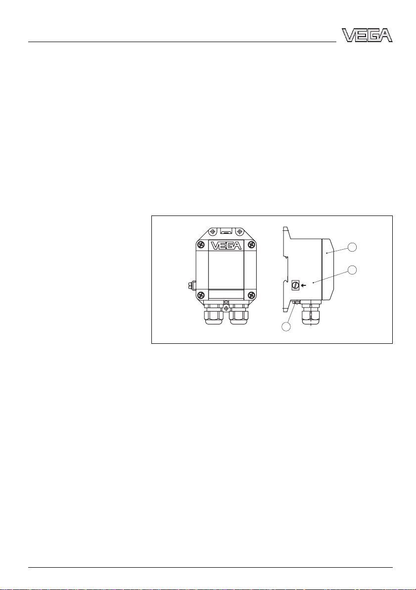
VEGABOX 01 consists of the following components:
l Breather housing
l Protective cover (optional)
1
2
3
Fig. 1: VEGABOX 01
1 Housing cover
2 Housing
3 Breather facility
3.2 Principle of operation
Area of application
Power supply
6 VEGABOX 01
VEGABOX 01 is a breather housing for pressure transmitters
with connection cable with integrated capillary cable. Itis
particularly suitable for the following VEGA pressure transmitters:
l VEGAWELL 72 4 … 20 mA
l VEGAWELL 72 4 … 20 mA/HART
l VEGABAR 74 4 … 20 mA/HART
l VEGABAR 75 4 … 20 mA/HART
The connection cable of the sensor as well as the power
supply cable are connected to the VEGABOX 01. Connection
is carried out via screw terminals.
32771-EN-061121
Page 7

3.3 Storage and transport
Product description
Packaging
Storage and transport tem-
perature
Your instrument was protected by packaging during transport.
Its capacity to handle normal loads during transport is assured
by a test according to DIN EN 24180.
The packaging of standard instruments consists of environ-
ment-friendly, recyclable cardboard. For special versions, PE
foam or PE foil is also used. Dispose of the packaging material
via specialised recycling companies.
l Storage and transport temperature see "Supplement -
Technical data - Ambient conditions"
l Relative humidity 20 … 85 %
32771-EN-061121
VEGABOX 01 7
Page 8

Mounting
4 Mounting
4.1 General instructions
Installation position
Moisture
Mounting versions
VEGABOX 01 can be mounted in any position. However,
vertical mounting is recommended. This avoids pollution of the
breather facility and moisture penetration.
Note:
There must be the same atmospheric pressure on the breather
facility as well as on the measurement loop. Otherwise the
measured value can be adulterated.
Use the recommended cables (see chapter "Connecting to
power supply") and tighten the cable gland.
4.2 Mounting instructions
VEGABOX 01 can be mounted as follows:
l on carrier rail 35x7.5 according to EN 50022
l on mounting plate or on the wall
8 VEGABOX 01
32771-EN-061121
Page 9

Connecting to voltage supply
5 Connecting to voltage supply
5.1 Preparing the connection
Note safety instructions
Take note of safety
instructions for Ex
applications
Selecting connection cable
Generally note the following safety instructions:
l Connect only in the complete absence of line voltage
In hazardous areas you should take note of the appropriate
regulations, conformity and type approval certificates of the
sensors and power supply units.
VEGABOX 01 or VEGADIS 12 is connected with standard two-
wire cable without screen. An outer cable diameter of 5 … 9 mm
ensures the seal effect of the cable entry. If electromagnetic
interference is expected which is above the test values of
EN 61326 for industrial areas, we recommend the use of
screened cable.
Fig. 2: Connection of VEGABOX 01 to the sensor
32771-EN-061121
VEGABOX 01 9
Page 10

Connecting to voltage supply
Select connection
cable for Ex applications
Cable screening and grounding
Cable screen and grounding
for Ex applications
Take note of the corresponding installation regulations for Ex
applications.
If screened cable is necessary, connect the cable screen on
both ends to ground potential. In the VEGABOX 01 or
VEGADIS 12, the screen must be connected directly to the
internal ground terminal. The ground terminal on the outside of
the housing must be connected to the potential equalisation
(low impedance).
If potential equalisation currents are expected, the connection
on the processing side must be made via a ceramic capacitor
(e.g. 1 nF, 1500 V). The low frequency potential equalisation
currents are thus suppressed, but the protective effect against
high frequency interference signals remains.
In Ex applications, grounding on one sensor side is recommended, see EN 60079-14.
5.2 Connection procedure
Proceed as follows:
1 Unscrew the housing cover
2 Loosen compression nut of the cable entry
3 Remove approx. 10 cm of the cable mantle, strip approx.
1 cm insulation from the individual wires
4 Insert the cable into VEGABOX 01 through the cable entry
5 Loosen the screw terminals with a screwdriver
6 Insert the wire ends into the open terminals according to
the wiring plan
7 Tighten screw terminals again
8 Check the hold of the wires in the terminals by lightly
pulling on them
9 Connect the screen to the ground terminal
10 Connect the ground terminal outside on the housing
according to specification (low impedance)
11 Tighten the compression nut of the cable entry. The seal
ring must completely encircle the cable
12 Screw the housing cover back on
The electrical connection is finished.
32771-EN-061121
10 VEGABOX 01
Page 11

Connection to VEGAWELL 72
4 … 20 mA
Connecting to voltage supply
5.3 Wiring plan
Zum Anschluss an
For connection to
Druckmessumformer mit
pressure transmitters with
analogem Ausgangssignal
analog output
1
23
10
11 12
–
+
VEGABOX 01
–
+
TRANSMITTER
5 6
4
+
–
Fig. 3: Terminal assignment VEGABOX 01
1 To power supply or the the processing system
2 Control instrument (4 … 20 mA measurement)
3 Yellow and white to processing of the integrated PT100 (option)
4 Screen
5 Breather capillaries
6 Suspension cable
1)
+
1
–
+
2
–
3
Wire number Wire colour/Polarity Terminal VEGABOX
01
1 brown (+) 1
2 blue (-) 2
1)
Connect screen to ground terminal. Connect ground terminal outside on the
housing as prescribed. The two terminals are galvanically connected.
32771-EN-061121
VEGABOX 01 11
Page 12

Connecting to voltage supply
Connection to VEGAWELL 72,
VEGABAR 74, 75 4 … 20 mA/
HART
4 5
Zum Anschluss an
For connection to
Druckmessumformer mit
pressure transmitters with
analogem Ausgangssignal
analog output
1
23
10
11 12
+
TRANSMITTER
–
VEGABOX 01
–
+
3
+
–
+
–
Fig. 4: Terminal assignment VEGABOX 01
1 To power supply or the the processing system
2 Control instrument (4 … 20 mA measurement)
3 Screen
2)
4 Breather capillaries
5 Suspension cable
Wire number Wire colour/Polarity Terminal VEGABOX
01
1 brown (+) 1
2 blue (-) 2
3 Yellow 3
1
2
2)
Connect screen to ground terminal. Connect ground terminal outside on the
housing as prescribed. The two terminals are galvanically connected.
12 VEGABOX 01
32771-EN-061121
Page 13

Set up
6 Set up
6.1 Setup procedure
Setup and adjustment of the respective sensor is carried out
according to the operating instructions manual of the sensor.
32771-EN-061121
VEGABOX 01 13
Page 14

Maintenance and fault rectification
7 Maintenance and fault rectification
7.1 Maintenance
When used as directed in normal operation, VEGABOX 01 is
completely maintenance free.
7.2 Instrument repair
If a repair is necessary, please proceed as follows:
You can download a return form (23 KB) in the Internet from
our homepage
and Certificates - Repair form".
By doing this you help us carry out the repair quickly and
without having to call back for needed information.
l Print and fill out one form per instrument
l Clean the instrument and pack it damage-proof
l Attach the filled in form and if necessary, a safety data
sheet to the instrument
l Please ask the agency serving you for the address of your
return shipment. You find the respective agency on our
website
wide"
www.vega.com under: "Downloads - Forms
www.vega.com under: "Company - VEGA world-
14 VEGABOX 01
32771-EN-061121
Page 15

Dismounting
8 Dismounting
8.1 Dismounting procedure
Warning:
Before dismounting, be aware of dangerous process conditions such as e.g. pressure in the vessel, high temperatures,
corrosive or toxic products etc.
Take note of chapters "Mounting" and "Connecting to power
supply" and carry out the listed steps in reverse order.
8.2 Disposal
The instrument consists of materials which can be recycled by
specialised recycling companies. We use recyclable materials
and have designed the electronic modules to be easily
separable.
WEEE directive 2002/96/EG
This instrument is not subject to the WEEE directive 2002/96/
EG and the respective national laws (in Germany, e.g.
ElektroG). Pass the instrument directly on to a specialised
recycling company and do not use the municipal collecting
points. These may be used only for privately used products
according to the WEEE directive.
Correct disposal avoids negative effects to persons and
environment and ensures recycling of useful raw materials.
Materials: see "Technical data"
If you cannot dispose of the instrument properly, please
contact us about disposal methods or return.
32771-EN-061121
VEGABOX 01 15
Page 16

Supplement
9 Supplement
9.1 Technical data
General data
316L corresponds to 1.4404 or 1.4435, 316Ti corresponds to 1.4571
Materials
- Housing plastic PBT
- Ground terminal 316Ti/316L
Weight approx. 0.5 kg (1.102 lbs)
Ambient conditions
Ambient temperature -40 … +85 °C (-40 … +185 °F)
Storage and transport temperature -40 … +85 °C (-40 … +185 °F)
Electromechanical data
Cable gland 2x cable entry M20x1.5 (cable-ø 5 … 9 mm)
Screw terminals for
Supply and signal circuit
Supply voltage see operating instructions manual of the
Max. input current 150 mA
wire cross-section up to 2.5 mm²
respective sensor
Electrical protective measures
Protection IP 65
Overvoltage category III
Protection class III
Approvals
3)
ATEX for connection to pressure transmitters with
ATEX certificate
Ship approvals GL, LRS, ABS, CCS, RINA, DNV
3)
Deviating data in Ex applications: see separate safety instructions.
16 VEGABOX 01
32771-EN-061121
Page 17

9.2 Dimensions
VEGABOX 01
38mm
1
(1
/2")
ø 5mm
/
13
(
Supplement
53
72mm (2
")
64
/64")
M20x1,5
Fig. 5: VEGABOX 01
VEGABOX 01 with protective cover
100mm (3 15/16") 72mm (2
")
")
64
/
16
/
41
5
118mm (4
135mm (5
")
32
/
15
139mm (5
")
4
/
1
108mm (4
")
32
/
11
85mm (3
53
/64")
")
8
/
1
130mm (5
Fig. 6: VEGABOX 01 with protective cover
32771-EN-061121
VEGABOX 01 17
Page 18

Supplement
9.3 Industrial property rights
VEGA product lines are global protected by industrial property rights.
Further information see http://www.vega.com.
Only in U.S.A.: Further information see patent label at the sensor housing.
VEGA Produktfamilien sind weltweit geschützt durch gewerbliche Schutzrechte.
Nähere Informationen unter http://www.vega.com.
Les lignes de produits VEGA sont globalement protégées par des droits de
propriété intellectuelle.
Pour plus d'informations, on pourra se référer au site http://www.vega.com.
VEGA lineas de productos están protegidas por los derechos en el campo de la
propiedad industrial.
Para mayor información revise la pagina web http://www.vega.com.
Линии продукции фирмы ВЕГА защищаются по всему миру правами на
интеллектуальную собственность.
Дальнейшую информацию смотрите на сайте http://www.vega.com.
德(VEGA)系列品在全球享有知保。
一步信息网站<http://www.vega.com>。
9.4 Trademark
All brands used as well as trade and company names are
property of their lawful proprietor/originator.
18 VEGABOX 01
32771-EN-061121
Page 19

Supplement
32771-EN-061121
VEGABOX 01 19
Page 20

VEGA Grieshaber KG
Am Hohenstein 113
77761 Schiltach
Germany
Phone +49 7836 50-0
Fax +49 7836 50-201
E-mail: info@de.vega.com
www.vega.com
ISO 9001
All statements concerning scope of delivery, application,
practical use and operating conditions of the sensors and
processing systems correspond to the information avail-
able at the time of printing.
© VEGA Grieshaber KG, Schiltach/Germany 2006
Subject to change without prior notice 32771-EN-061121
 Loading...