

Page 1
Supplementary instructions
External housing
For pressure transmitter VEGABAR
Document ID: 31087
Page 2

Contents
Contents
1 About this document
1.1 Function ........................................................................................................................... 3
1.2 Target group ..................................................................................................................... 3
1.3 Symbolism used ............................................................................................................... 3
2 For your safety
2.1 Authorised personnel ....................................................................................................... 4
2.2 Appropriate use ................................................................................................................ 4
2.3 Environmental instructions ............................................................................................... 4
3 Product description
3.1 Conguration .................................................................................................................... 5
3.2 Principle of operation........................................................................................................ 5
3.3 Storage and transport....................................................................................................... 5
4 Mounting
4.1 Mounting preparations ..................................................................................................... 7
4.2 Exchange of the electronics module ................................................................................. 7
4.3 Mounting steps, external housing ..................................................................................... 8
5 Connect the sensor to the external housing
5.1 Preparing the connection ............................................................................................... 10
5.2 Connection procedure .................................................................................................... 10
5.3 Wiring plan ..................................................................................................................... 11
6 Setup
6.1 Setup .............................................................................................................................. 14
7 Maintenance
7.1 Instrument repair ............................................................................................................ 15
8 Dismounting
8.1 Dismounting steps.......................................................................................................... 16
8.2 Disposal ......................................................................................................................... 16
9 Supplement
9.1 Technical data ................................................................................................................ 17
9.2 Dimensions .................................................................................................................... 18
31087-EN-130322
Safety instructions for Ex areas
PleasenotetheEx-specicsafetyinformationforinstallationandoperation in Ex areas. These safety instructions are part of the operating
instructions manual and come with the Ex-approved instruments.
Editing status: 2013-03-11
2
External housing • For pressure transmitter VEGABAR
Page 3
1 About this document
1 About this document
1.1 Function
This supplementary manual, together with the attached operating
instructions manual, has all the information you need for quick setup
and safe operation. Please read this manual before you start setup.
1.2 Target group
This operating instructions manual is directed to trained specialist
personnel. The contents of this manual should be made available to
these personnel and put into practice by them.
1.3 Symbolism used
Information, tip, note
This symbol indicates helpful additional information.
Caution: If this warning is ignored, faults or malfunctions can result.
Warning: If this warning is ignored, injury to persons and/or serious
damage to the instrument can result.
Danger: If this warning is ignored, serious injury to persons and/or
destruction of the instrument can result.
Ex applications
This symbol indicates special instructions for Ex applications.
List
•
The dot set in front indicates a list with no implied sequence.
Action
→
This arrow indicates a single action.
1 Sequence
Numbers set in front indicate successive steps in a procedure.
31087-EN-130322
External housing • For pressure transmitter VEGABAR
3
Page 4

2 For your safety
2 For your safety
2.1 Authorised personnel
All operations described in this operating instructions manual must
be carried out only by trained specialist personnel authorised by the
plant operator.
During work on and with the device the required personal protective
equipment must always be worn.
2.2 Appropriate use
The external housing is a replacement part for a pressure transmitter
VEGABAR series 50 and 60 in IP 68 (25 bar) version.
2.3 Environmental instructions
Protection of the environment is one of our most important duties.
That is why we have introduced an environment management system
with the goal of continuously improving company environmental pro-
tection.Theenvironmentmanagementsystemiscertiedaccording
to DIN EN ISO 14001.
Pleasehelpusfulllthisobligationbyobservingtheenvironmental
instructions in this manual:
Chapter "Storage and transport"
•
Chapter "Disposal"
•
31087-EN-130322
4
External housing • For pressure transmitter VEGABAR
Page 5
Scope of delivery
3 Product description
3.1 Conguration
The scope of delivery encompasses:
External housing
•
Documentation
•
– this operating instructions manual
3 Product description
Constituent parts
Application area
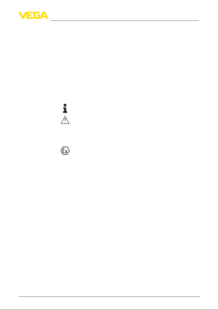
The external housing consists of the components electronics housing
and base. Both components are available in plastic or stainless steel.
Dependingontheorderspecication,thescrew-oncoverofthe
electronics housing is available with or without inspection window for
the display and adjustment module.
1
2
3
4
Fig. 1: Components of the external housing for VEGABAR - plastic version
1 Screw-on cover
2 Electronics housing
3 Socket
4 Wall mounting plate
3.2 Principle of operation
The external housing is suitable for the following pressure transmitters
in IP 68 (25 bar) version:
VEGABAR 51, 52, 53, 54, 55
•
VEGABAR 66, 67
•
3.3 Storage and transport
Packaging
Your instrument was protected by packaging during transport. Its
capacity to handle normal loads during transport is assured by a test
based on ISO 4180.
The packaging of standard instruments consists of environmentfriendly, recyclable cardboard. For special versions, PE foam or PE
foil is also used. Dispose of the packaging material via specialised
recycling companies.
•
31087-EN-130322
External housing • For pressure transmitter VEGABAR
5
Page 6

3 Product description
Storage and transport
temperature
Storage and transport temperature see chapter "Supplement -
•
Technical data - Ambient conditions"
Relative humidity 20 … 85 %
•
31087-EN-130322
6
External housing • For pressure transmitter VEGABAR
Page 7

Tools
4 Mounting
4 Mounting
4.1 Mounting preparations
The following tools are required for mounting the external housing.
Plastic housing:
Allen wrench size 4
•
Fork wrench, wrench size 19
•
Stainless steel housing:
Fork wrench, wrench size 8
•
Fork wrench, wrench size 19
•
4.2 Exchange of the electronics module
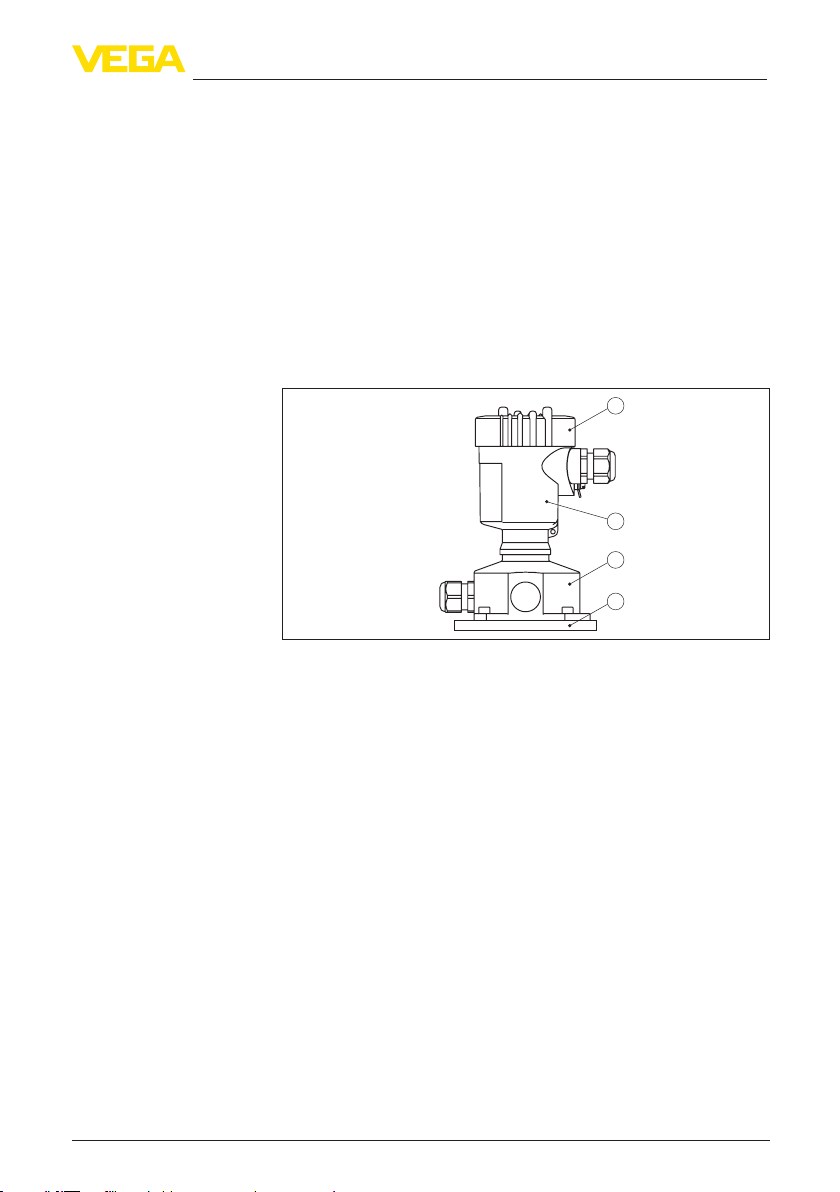
The electronics module is located in the electronics compartment.
The below illustration shows the position of the electronics compartment in an external housing.
1
Fig. 2: Single chamber housing
1 Position of the electronics compartment
Dismounting the electronics module
31087-EN-130322
External housing • For pressure transmitter VEGABAR
Proceed as follows to remove the electronics module from the existing
housing:
1. Switchopowersupply
2. Unscrew housing cover of the electronics compartment
3. Disconnect the connection cables according to the operating
instructions manual of the respective sensor
4. Loosen the two holding screws with a screwdriver (Torx size T 10
or slotted screwdriver size 4)
7
Page 8

4 Mounting
1
2
Fig. 3: Loosen the holding screws of the electronics module
1 Electronics module
2 Screws (2 pcs.)
5. Pull the electronics out by holding the opening levers.
Mounting the electronics
module
To dismount the electronics module from the new housing, proceed
as follows:
1. Insert the electronics module carefully into the new housing.
Information:
The electronics module is connected via a plug. Make sure that the
plug is in the correct position. The marking notch must be in position
"18.00 h".
1
Fig. 4: Plug position in the base of the external housing
1 Notch
2. Screw in and tighten the two screws with the screwdriver.
3. Screw the housing cover back on
Theexchangeoftheelectronicsmoduleisnished.
As a rule, an exchange of electronics must be documented internally
when Ex applications are involved.
31087-EN-130322
Wall mounting - External
housing
8
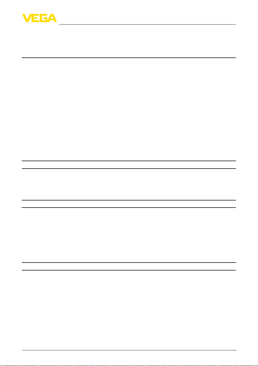
4.3 Mounting steps, external housing
1. Mark the holes according to the following drilling template
External housing • For pressure transmitter VEGABAR
Page 9

4 Mounting
2. Depending on the mounting surface, fasten the wall mounting
plate with 4 screws
90 mm (3.54")
70 mm (2.76")
3mm
(0.12")
R 3,5 mm
(0.14")
93 mm (3.66")
110 mm (4.33")
Fig. 5: Hole pattern - wall mounting plate (external housing)
8 mm
(0.32")
Tip:
Mount the wall mounting plate in such a way that the cable gland of
the base points downward. Rain and condensation water can thus
draino.
The base of stainless steel can be displaced in 90° increments on the
wall mounting plate, the base of plastic by 180°.
Turn the cable gland of the electronics housing downward. The housing can be turned by 330° without the use of any tools.
Warning:
With the plastic housing, the four screws of the base may only be
screwedinhandtight.Exceedingthemax.torquespeciedinchapter
"Technical data" can damage the wall mounting plate.
31087-EN-130322
External housing • For pressure transmitter VEGABAR
9
Page 10

5 Connect the sensor to the external housing
5 Connect the sensor to the external
housing
5.1 Preparing the connection
Follow the instructions in the operating instructions manual of the
sensor.
5.2 Connection procedure
Proceed as follows to connect the external housing:
1. Loosen the four screws on the base with a hexagon key or fork
wrench
2. Remove the mounting plate from the base
1
3
2
Fig. 6: Removing the mounting plate on the base
1 Screws
2 Wall mounting plate
3 Cable gland
3. Loop the connection cable through the cable entry on the housing
Tip:
With plastic housing, the cable gland can be mounted in three positions each displaced by 90°. Simply exchange the cable gland against
theblindpluginthettingthreadedhole.
Note:
Depending on the delivery date of the sensor, the connection cable
maybeequippedwiththreeorfourwires.Takenoteofthedierent
assignments of the terminals in the housing base in "Wiring plan".
4. With four-wire sensor, remove the bridge between terminal 4 and
1)
1)
base
the ground terminal, see "Wiring plan".
The connection cable comes pre-assembled. If necessary, shorten it to the
requested length, cut the breather capillaries clean. Remove approx. 5 cm of
the cable mantle, strip approx. 1 cm insulation from the ends of the individual
wires. After shortening the cable, fasten the type plate with support back on
the cable.
31087-EN-130322
10
External housing • For pressure transmitter VEGABAR
Page 11

Overview - VEGABAR
series 50
5 Connect the sensor to the external housing
5. Connect the wire ends as described in chapter "Connection plan".
Take note of the numbering.
6. Connect the screen to the internal ground terminal, connect the
outer ground terminal to potential equalisation
7. Tighten the compression nut of the cable entry. The seal ring must
completely encircle the cable
8. Attach the mounting plate again and tighten the screws
The electrical connection of the sensor to the external housing is
nished.
Youndtheelectricalconnectionoftheelectronicsmoduleinchapter
"Wiring plan" or in the operating instructions manual of the respetive
sensor.
5.3 Wiring plan
Fig. 7: External housing in conjunction with VEGABAR 51, 52, 53, 54, 55
31087-EN-130322
External housing • For pressure transmitter VEGABAR
11
Page 12

5 Connect the sensor to the external housing
Overview - VEGABAR
series 60
Fig. 8: External housing in conjunction with VEGABAR 66, 67
Terminal compartment
12
1234
2
341
6
5
Fig. 9: Connection of the sensor in the housing base
1 Brown
2 Blue
3 Yellow
4 White
5 Shielding
6 Breather capillaries
External housing • For pressure transmitter VEGABAR
31087-EN-130322
Page 13

Wiring plan external
electronics
5 Connect the sensor to the external housing
12 5 678
1
Fig. 10: Wiring plan, electronics
1 Voltage supply
Display
I2C
31087-EN-130322
External housing • For pressure transmitter VEGABAR
13
Page 14

6 Setup
6 Setup
6.1 Setup
Setup is carried out according to the operating instructions manual of
the respective sensor.
14
31087-EN-130322
External housing • For pressure transmitter VEGABAR
Page 15

7 Maintenance
7 Maintenance
7.1 Instrument repair
If an instrument repair is necessary, please proceed as follows:
You can download a return form (23 KB) from our Internet homepage
www.vega.com under: "Downloads - Forms and certicates - Repair
form".
By doing this you help us carry out the repair quickly and without having to call back for needed information.
Printandlloutoneformperinstrument
•
Clean the instrument and pack it damage-proof
•
Attach the completed form and possibly also a safety data sheet to
•
the instrument
Send the instrument to the address of the agency serving you. In
•
Germany, send it to the company headquarters in Schiltach.
31087-EN-130322
External housing • For pressure transmitter VEGABAR
15
Page 16

8 Dismounting
8 Dismounting
8.1 Dismounting steps
Take note of chapters "Mounting" and "Connect sensor to the external
housing" and carry out the listed steps in reverse order.
8.2 Disposal
The instrument consists of materials which can be recycled by
specialised recycling companies. We have purposely designed the
electronic modules to be easily separable. Mark the instrument as
scrap and dispose of it according to national government regulations
(e.g. in Germany according to electronic scrap ordinance).
Materials: see chapter "Technical data"
If you have no way to dispose of the old instrument properly, please
contact us concerning return and disposal.
16
31087-EN-130322
External housing • For pressure transmitter VEGABAR
Page 17
9 Supplement
9 Supplement
9.1 Technical data
General data
Material 316L corresponds to 1.4404 or 1.4435
Materials, non-wetted parts
Ʋ Electronics housing plastic PBT (Polyester), 316L
Ʋ Socket plastic PBT (Polyester), 316L
Ʋ Wall mounting plate plastic PBT (Polyester), 316L
Ʋ Seal between base and wall mounting
plate
Ʋ Seal between housing and housing
cover
Ʋ Ground terminal 316L
Torque of base screws for plastic housing
max.
Weight approx. 0.7 … 2.0 kg (1.543 … 4.409 lbs), depending on housing
Process conditions
Ambient, storage and transport temperature
Ʋ without display and adjustment
module
Ʋ With display and adjustment module -20 … +70 °C (-4 … +158 °F)
TPE(xedconnected)
Silicone (plastic housing), NBR (stainless steel housing)
5 Nm (3.688 lbf ft)
material
-40 … +80 °C (-40 … +176 °F)
Electromechanical data
Options of the cable entry
Ʋ Cable gland M20 x 1.5 (cable: ø 5 … 9 mm)
Ʋ Cable entry ½ NPT
Ʋ Blind plug M20 x 1.5; ½ NPT
Ʋ Closing cap M20 x 1.5; ½ NPT
Wire cross-section (spring-loaded
up to 2.5 mm² (AWG 14)
terminals)
Electrical protective measures
Protection, depending on housing version
Ʋ Plastic housing IP 66/IP 67
Ʋ Stainless steel housing IP 66/IP 68 (0.2 bar)
2)
The prerequisites for maintaining the protection rating are a suitable cable as well as correct mounting.
31087-EN-130322
2)
External housing • For pressure transmitter VEGABAR
17
Page 18

9 Supplement
9.2 Dimensions
Electronics housing
69 mm (2.72 ")
ø77 mm (3.03")
~ 59 mm
(2.32")
ø 80 mm
(3.15")
M20x1,5/
½ NPT
112 mm (4.41")
M20x1,5/
1
½ NPT
2
112 mm (4.41")
Fig. 11: Electronics housing (with integrated display and adjustment module the housing is 9 mm/0.35 in higher)
1 Plastic housing
2 Stainless steel housing
External housing with sensor in IP 68 (25 bar) version
65 mm
(2.68")
42mm
(2.68")
68 mm
(1.65")
1
(3.62")
92 mm
40mm
(1.57")
2
Fig. 12: External housing - Plastic version
1 Lateral cable outlet
2 Axial cable outlet
110 mm x 90 mm (4.33" x 3.54")
~ 66 mm (2.60")
59 mm (2.32")
18
31087-EN-130322
External housing • For pressure transmitter VEGABAR
Page 19

68 mm
(2.68")
42mm
(1.65")
1
68 mm
(2.68")
9 Supplement
51 mm (2.01")
(3.62")
92 mm
40mm
(1.57")
2
Fig. 13: External housing - Stainless steel version
1 Lateral cable outlet
2 Axial cable outlet
3 Seal 2 mm (0.079 in)
110 mm x 90 mm (4.33" x 3.54")
3
31087-EN-130322
External housing • For pressure transmitter VEGABAR
19
Page 20

Printing date:
All statements concerning scope of delivery, application, practical use and operating conditions of the sensors and processing systems correspond to the information
available at the time of printing.
Subject to change without prior notice
© VEGA Grieshaber KG, Schiltach/Germany 2013
VEGA Grieshaber KG
Am Hohenstein 113
77761 Schiltach
Germany
Phone +49 7836 50-0
Fax +49 7836 50-201
E-mail: info.de@vega.com
www.vega.com
31087-EN-130322
 Loading...