

Page 1
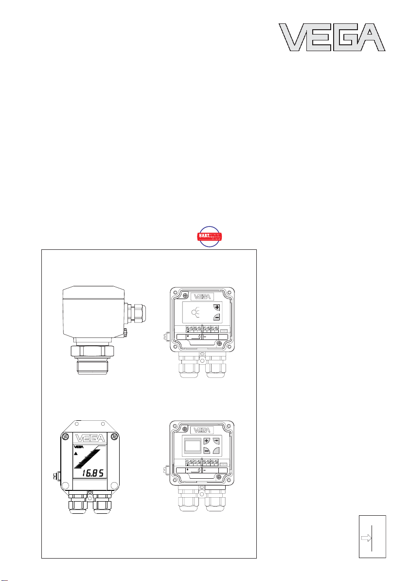
Operating Instructions
VEGABAR 44 (HART®)
WE'VE GOT
ABILITY
OPERATE
t
i
ZERO
SPAN
123 5678
-
+
VEGADIS 10
+
4...20mA
E12
123 5678
-
+
VEGADIS 10
+
4...20mA
E12
AM10
OK
AM10
p
Page 2
Contents
Safety information ........................................................................ 2
Note Ex area ................................................................................ 2
1 Product description
1.1 Function and configuration .................................................. 4
1.2 Self-monitoring ..................................................................... 4
1.3 Technical data ....................................................................... 5
1.4 Approvals and certificates .................................................. 9
1.5 Dimensions ......................................................................... 10
2 Mounting
2.1 Mounting instructions ......................................................... 12
2.2 Compensation of the atmospheric pressure ................... 12
3 Electrical connection
3.1 Connection instructions ..................................................... 12
3.2 Connection diagram .......................................................... 13
3.3 Connection examples ........................................................ 14
Contents
Safety information
Please read this manual carefully, and also take
note of country-specific installation standards
(e.g. the VDE regulations in Germany) as well
as all prevailing safety regulations and accident prevention rules.
For safety and warranty reasons, any internal
work on the instruments, apart from that involved in normal installation and electrical connection, must be carried out only by qualified
VEGA personnel.
2 VEGABAR 44 (HART®)
Note Ex area
Please note the attached safety instructions
containing important information on installation
and operation in Ex areas.
These safety instructions are part of the
operating instructions and come with the Ex
approved instruments.
Page 3

Contents
4 Setup
4.1 Indicating module ............................................................... 15
4.2 Setup with module
"Adjustment of the basic functions“ .................................. 15
4.3 Setup with module
"Menu-driven adjustment with additional functions“ ........ 17
4.4 Setup with adjustment software
VEGA Visual Operating (VVO) ......................................... 22
4.5 Setup with HART® handheld ............................................. 30
5 Diagnostics
5.1 Maintenance ....................................................................... 36
5.2 Failure rectification ............................................................. 36
6 Instrument modification
6.1 Exchange of adjustment modules .................................... 38
6.2 Exchange of electronics .................................................... 39
6.3 Exchange of the hygienic form seal on VEGABAR 44 .... 40
VEGABAR 44 (HART®) 3
Page 4

1 Product description
Product description
1.1 Function and configuration
VEGABAR 44 process pressure transmitters
are efficient instruments for process pressure measurement. As pressure sensor
element, the dry ceramic-capacitive measuring cell CERTEC® is used. The process pressure causes a capacitance change within the
measuring cell via the diaphragm. This capacitance change is detected by an ASIC
(Application specific integrated circuit) and
converted into a pressure-proportional signal
by the integrated sensor electronics with
microcontroller. Precise, high-resolution digital processing of measured data ensures
excellent technical data.
The electronics module is powered by a
separate VEGA signal conditioning instrument, a stabilised power supply unit or a PLC
(active input). After the adjustment, a standardised 4 … 20 mA current signal is made
available which can be displayed (e.g. in
PLC systems) or further processed.
For carrying out adjustment, the following
alternatives are available:
- adjustment module directly on VEGABAR
- adjustment module in external housing
(VEGADIS 10)
- via PC with adjustment software VEGA
Visual Operating (VVO)
- with HART® handheld
1.2 Self-monitoring
To improve reliability, the functionality of important electronic components is constantly
checked, and internal parameters such as
sensor value, temperature and operating
voltage are closely monitored.
VEGABAR 40 with ceramic CERTEC® measuring cell offers the advantage of continuous
self-monitoring. The measuring and reference
capacitances of the measuring cell constitute
a predefined ratio over the entire measuring
range. Any deviation from these data is a
reliable indicator of a malfunction of the measuring cell.
If errors or malfunctions are detected during
these routines, the fault signal is triggered via
the 4 … 20 mA output (current jump to
3.6 mA or 22 mA).
4 VEGABAR 44 (HART®)
Page 5

Product description
1.3 T echnical data
Mechanical data
Materials, wetted parts
Process connection brass 2.041, stainless steel 1.4571
Diaphragm saphire-ceramic® (99.9 % Oxide ceramic)
Seal, measuring cell Viton, EPDM, Hifluour, Kalrez
Materials, non-wetted parts
Housing high resistance plastic PBT (Polyester)
- optional Alu-die casting, powder-coated
Ground terminal stainless steel 1.4305
Indicating module window Lexan
Weight
VEGABAR approx. 0.8 kg (depending on process fitting)
Adjustment and indicating elements
Adjustment of the basic functions 2 keys, 1 rotary-type switch
Menu-driven adjustment with
additional functions
- adjustment elements 4 keys
- indicating elements DOT-matrix display, 3 lines with 7 figures each
Indicating module LC display with
- bar graph (20 segments)
- digital value (4 digits)
- tendency indicators for rising or falling values
VEGABAR 44 (HART®) 5
Page 6
Product description
Nominal measuring ra nge
Gauge pressure
resistance
Low pressu re
resistance
Gauge pressure
0…0,1 bar / 0…10 kPa 15 bar / 1 500 kPa -0,2 bar / -20 kPa
0…0,2 bar / 0…20 kPa 20 bar / 2 000 kPa -0,4 bar / -40 kPa
0…0,4 bar / 0…40 kPa 30 bar / 3 000 kPa -0,8 bar / -80 kPa
0…1,0 bar / 0…100 kPa 35 bar / 3 500 kPa -1,0 bar / -100 kPa
0…2,5 bar / 0…250 kPa 50 bar / 5 000 kPa -1,0 bar / -100 kPa
0…5,0 bar / 0…500 kPa 65 bar / 6 500 kPa -1,0 bar / -100 kPa
0…10,0 bar / 0…1 000 kPa 90 bar / 9 000 kPa -1,0 bar / -100 kPa
0…20,0 bar / 0…2 000 kPa 130 bar / 13 000 kPa -1,0 bar / -100 k Pa
0…40,0 bar / 0…4 000 kPa 200 bar / 20 000 kPa -1,0 bar / -100 k Pa
0…60,0 bar / 0…6 000 kPa 300 bar / 30 000 kPa -1,0 bar / -100 k Pa
-0,05…+0,05 bar / -5…+5 kPa 15 bar / 1 500 kPa -0,2 bar / -20 kPa
-0,1…+0,1 bar / -10…+10 kPa 20 bar / 2 000 kPa -0,4 bar / -40 kPa
-0,2…+0,2 bar / -20…+20 kPa 30 bar / 3 000 kPa -0,8 bar / -80 kPa
-0,5…+0,5 bar / -50…+50 kPa 35 bar / 3 500 kPa -1,0 bar / -100 kPa
-1,0…0,0 bar / -100…0 kPa 35 bar / 3 500 kPa -1,0 bar / -100 kPa
-1,0…+1,5 bar / -100…+150 kPa 50 bar /5 000 kPa -1,0 bar / -100 k Pa
-1,0…+4,0 bar / -100…+400 kPa 65 bar / 6 500 kPa -1,0 bar / -100 kPa
-1,0…+10,0 bar / -100…+1 000 kPa 90 bar / 9 000 kPa -1,0 bar / -100 k Pa
-1,0…+20,0 bar / -100…+2 000 kPa 130 bar / 13 000 k Pa -1,0 bar / -100 kPa
-1,0 …+40,0 bar / -100…+4 000 kPa 200 bar / 20 000 kPa -1,0 bar / -100 kPa
-1,0…+60,0 bar / -100…+6 000 kPa 300 bar / 30 000 k Pa -1,0 bar / -100 kPa
Absolute pressure
0…1,0 bar / 0…100 kPa 35 bar / 3 500 kPa
0…2,5 bar / 0…250 kPa 50 bar / 5 000 kPa
0…5,0 bar / 0 …500 kPa 65 bar / 6 500 kPa
0…10,0 bar / 0…1 000 kPa 90 bar / 9 000 k Pa
0…20,0 bar / 0…2 000 kPa 130 bar / 13 000 kPa
0…40,0 bar / 0…4 000 kPa 200 bar / 20 000 kPa
0…60,0 bar / 0…6 000 kPa 300 bar / 30 000 kPa
6 VEGABAR 44 (HART®)
Page 7
Product description
Electrical data
Adjustment ranges
Zero adjustable from -20 … +95 % of nominal range
Span adjustable from 3.3 … 120 % of nominal range
Supply and signal circuit
Supply voltage 12 … 36 V DC
Exd version (pressure-tight encapsulation) 18 … 36 V DC
Permissible residual ripple U
- at 500 Hz … 10 kHz U
Output signal
- range 3.8 … 20.5 mA
- resolution 6 µA
Current limiting approx. 22 mA
Fault signal 22 mA (3.6 mA)
Integration time 0 … 10 s adjustable
Rise time 85 ms (ti = 0 sec; 0 – 63 %)
Connection cable 2-wire
Max. permissible load dependent on the supply voltage
≤ 1 V
SS
≤ 10 mV
SS
(see load diagram)
1000
750
in Ohm
Ltotal
500
250
Load R
0
12
18 24 30 36
Voltage of the external energy UH in Volts
Display and adjustment circuit
For connection to VEGADIS 10 and/or indicating module
Data transmission digital
Connection cable 4-wire (standard cable)
Max. cable length 25 m
Connection
Cable entry M20 x 1.5 (for cable-ø 5 … 10 mm)
Screw terminals for conductor cross sections of up to 2.5 mm
2
Protective measures
Protection
1)
IP 65
Protection class III
Overvoltage category III
1)
Use of a suitable seal for the cable in the PG is necessary for maintaining the housing protection. If the seal
used does not fit the cable, it should be replaced by a suitable one.
VEGABAR 44 (HART®) 7
Page 8

Product description
Accuracy (similar to DIN 16 086, DIN V 19 259 - 1 and IEC 770)
Deviation
Reference conditions (acc. to IEC 770)
- temperature 15°C … 35°C
- rel. humidity 45 % … 75 %
- air pressure 860 mbar … 1060 mbar/86 kPa … 106 kPa
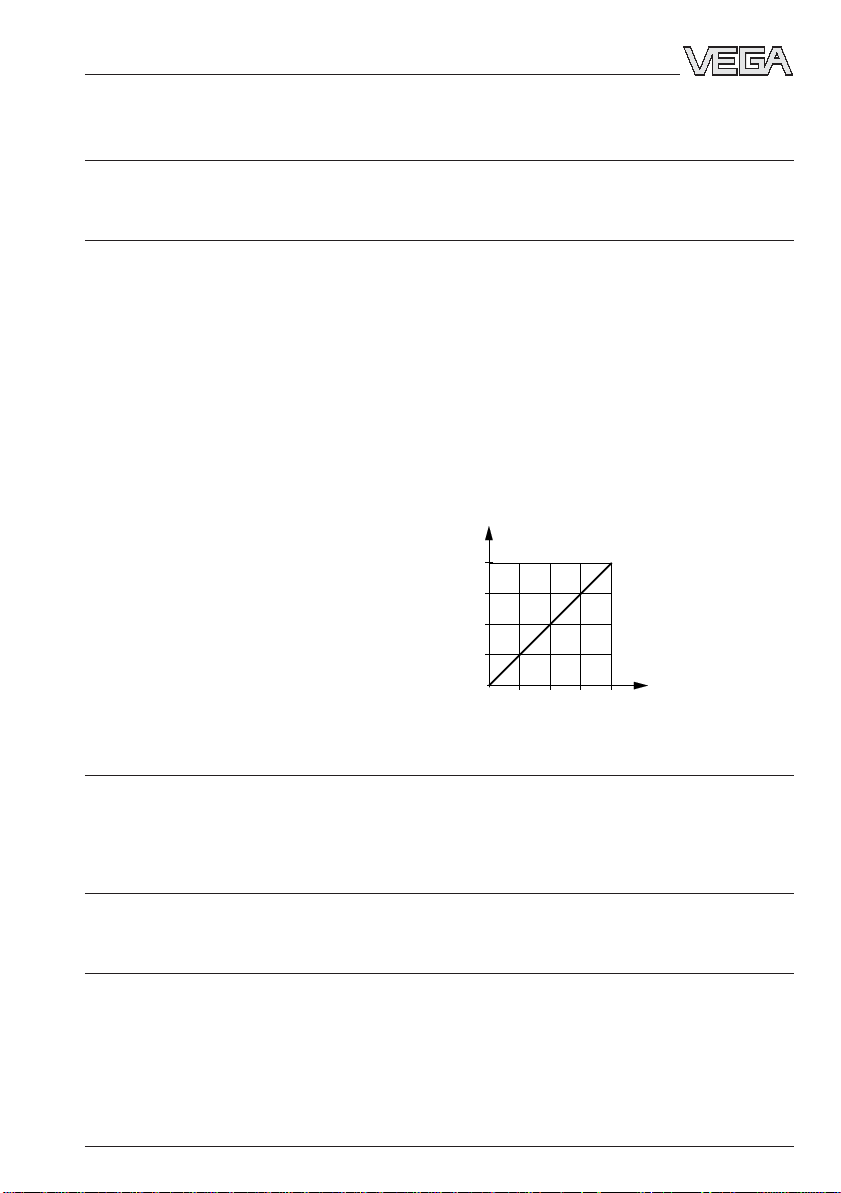
Determination of characteristics limit point adjustment acc. to DIN 16 086
Characteristics linear
Deviation in characteristics incl. hysteresis and repeatability
- Turn Down 1 : 1 < 0.25 % with accuracy class 0.25
- Turn Down up to 1 : 5 typ. < 0.3 % with accuracy class 0.25
- Turn Down up to 1 : 10 typ. < 0.4 % with accuracy class 0.25
Influence of the ambient temperature
Average temperature coefficient
of the zero signal
2)
- Turn Down 1 : 1 < 0.15 %/10 K with accuracy class 0.25
- Turn Down up to 1 : 5 typ. < 0.225 %/10 K with accuracy class 0.25
- Turn Down up to 1 : 10 typ. < 0.3 %/10 K with accuracy class 0.25
< 0.1 % with accuracy class 0.1
typ. < 0.1 % with accuracy class 0.1
typ. < 0.2 % with accuracy class 0.1
< 0.05 %/10 K with accuracy class 0.1
typ. < 0.075 %/10 K with accuracy class 0.1
typ. < 0.1 %/10 K with accuracy class 0.1
Long-term stability
Long-term drift of the zero signal
1) 3)
< 0.1 % per 2 years
Other actuating variables
Calibration position upright, diaphragm points downwards
Influence of the mounting position < 0.2 mbar/20 Pa
Vibration resistance mechanical vibrations with 4 g and
5 … 100 Hz, tested acc. to the regulations of
German Lloyd GL-characteristics 2
1)
Relating to the nominal measuring range.
2)
In the compensated temperature range of 0°C … +80°C, reference temperature 20°C.
3)
Acc. to IEC 770, point 6.1.2 relating to the nominal measuring range.
8 VEGABAR 44 (HART®)
Page 9
Product description
Operating conditions
Ambient conditions
Ambient temperature -40°C … +85°C
- with indicating module -20°C … +70°C
Storage and transport temperature -40°C … +85°C
Product temperature, dependent on the
seal material of the measuring cell
- Viton -20°C … +100°C
- EPDM -40°C … +100°C
- Kalrez 0°C … +100°C
1.4 Approvals and certificates
Approvals
- Ex Zone 2
- StEx Zone 10
- Ship approval
- CENELEC EEx ia IIC
- ATEX II 1G EEx ia IIC
- ATEX II 2G EExd ia IIC
If the use of approved instruments is required for certain applications, the relevant official
documents (test reports, test certificates and conformity certificates) must be observed.
These are supplied with the respective instrument.
CE conformity
VEGABAR 40 corresponds to the requirements of EMC (89/336/EWG) and NSR
(73/23/EWG). Conformity has been judged acc. to the following standards:
EMC Emission EN 50 081 - 1: 1992
NSR EN 61 010 - 1: 1993
Susceptibility EN 50 082 - 2: 1995
NAMUR regulations
Full compliance with the NAMUR regulations NE 21 and NE 43.
VEGABAR 44 (HART®) 9
Page 10
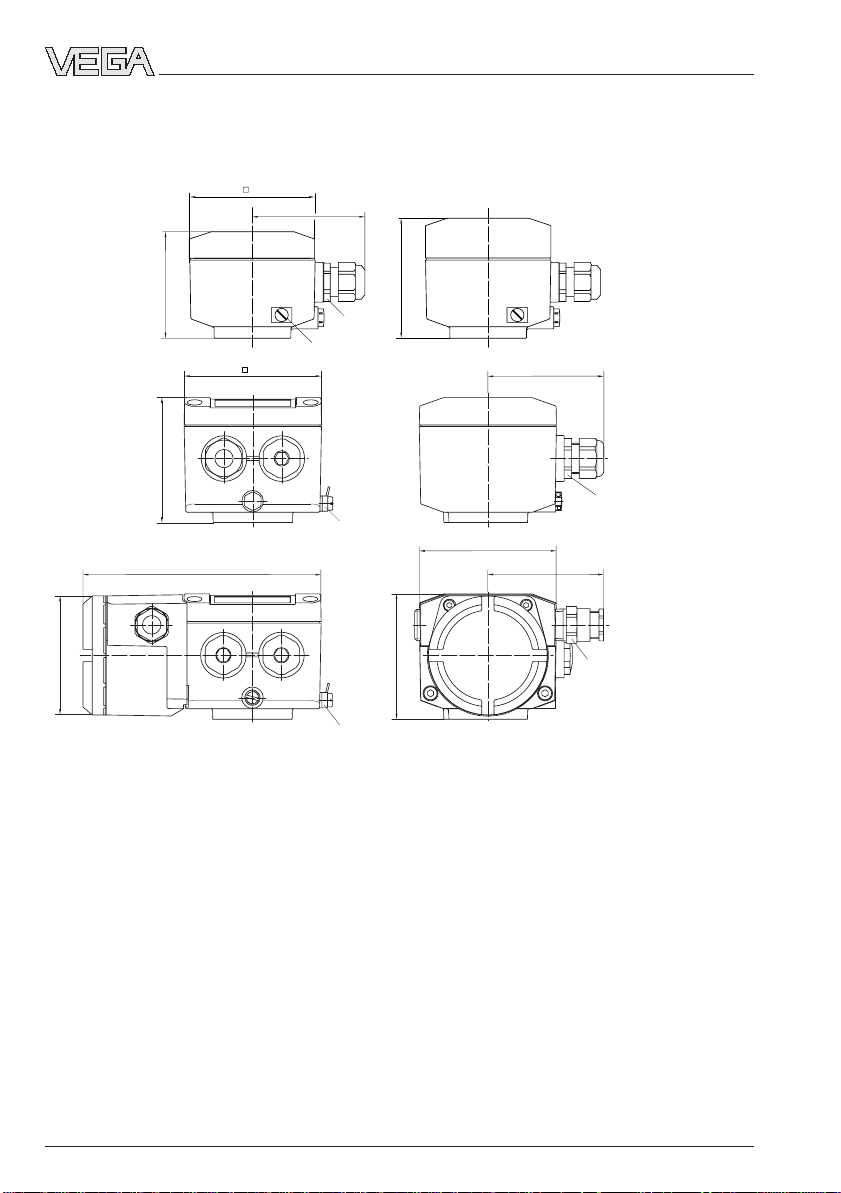
1.5 Dimensions
Housing without indicating module with indicating module
85
~76
72
Pg 13,5
82
Product description
Version
plastic PBT
90
Ground connection
~76
Version
Alu-die casting
82
M20x1,5
Ground connection
156
90
~76
Version
Alu-die casting
in EExd
78
Ground connection
82
½" NPT
10 VEGABAR 44 (HART®)
Page 11
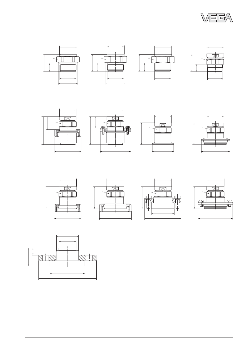
Product description
Process fitting
SW 60
25
34,5
64
ø 49,6
49
G 1½ A
ø 60
GW
ø 49,6
SW 46
64
ø 90
LB
ø 49,6
SW 46
ø 92
RB
ø 49,6
SW 60
49
24,5
G 1½ A
ø 55
49,5
GG
ø 49,6
SW 46
39
82
ø 78
82
LA
ø 49,6
SW 46
64
ø 78
RA
ø 64
ø 49,6
SW 60
25
SW 46
64
SW 46
ø 49,6
1½ " NPT
GN
ø 49,6
ø 64
CA
ø 49,6
ø 65,8
ø 105
AA
51,5
ø 49,6
SW 46
21
M44 x 1,25
BA/BB
ø 49,6
SW 46
64
ø 84
TA
ø 49,6
SW 46
64
ø 100
PA
20,5
51,5
ø 100
ø 165
FW
VEGABAR 44 (HART®) 11
Page 12
Mounting, Electrical connection
2 Mounting
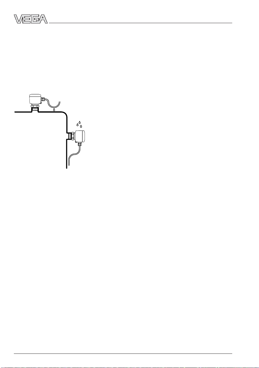
2.1 Mounting instructions
VEGABAR can be mounted in any position.
Cable entries must point downwards to avoid
moisture ingress. For this purpose, the housing can be rotated by 330° in relation to the
mounting part.
A seal, appropriate for connection, must be
used for mounting. This seal is either supplied with VEGABAR or must be provided by
the customer.
2.2 Compensation of the atmospheric pressure
On instruments for gauge pressure measurement, the atmospheric pressure is compensated via a breather facility integrated in
the housing.
3 Electrical connection
3.1 Connection instructions
The electronics in VEGABAR 44 requires a
supply voltage of 12 … 36 V DC. It is provided in two-wire technology, i.e. supply
voltage and current signal are led to the
terminals via the same two-wire connection
cable.
This external energy is provided via a separate power supply unit:
- power supply unit, e.g. VEGASTAB 690
- processing unit with integrated DC current
source (e.g. active PLC input)
- VEGAMET or VEGADIS 371
Make sure that the external energy source is
reliably separated from the mains circuits
acc. to DIN VDE 0106, part 101. The abovementioned VEGA instruments meet this requirement, and protection class II is therefore
ensured.
The external energy source must supply a
terminal voltage of at least 12 V to the transmitter. The actual terminal voltage on the
transmitter depends on the following factors:
- output voltage of the external energy
source under nominal load.
- electrical resistances of the connected
instruments in the circuit (see Connected
instruments, load resistor).
12 VEGABAR 44 (HART®)
Page 13
Electrical connection
Note the following instructions for electrical
connection:
- Connection must be made according to the
specific installation standards (e.g. in Germany acc. to the VDE regulations).
- Terminal voltage must not exceed 36 V, to
avoid damage to the electronics.
- Electrical connection must have a preventative measure against inadvertent
polarity reversal.
- The wiring between VEGABAR and the
power supply can be carried out using
standard two-wire cable.
- Screened cable is recommended, if strong
electromagnetic interference is to be expected. The shielding must be grounded at
both sensor ends. Please note the installation regulations for mounting in Ex areas.
- If overvoltages are expected, we recommend the installation of VEGA overvoltage
arresters.
- In the cable connection, a seal must be
used which fits the cable.
- For instrument version EExd (pressuretight encapsulation) screened cable must
be used for the instrument connection.
Note the installation regulations.
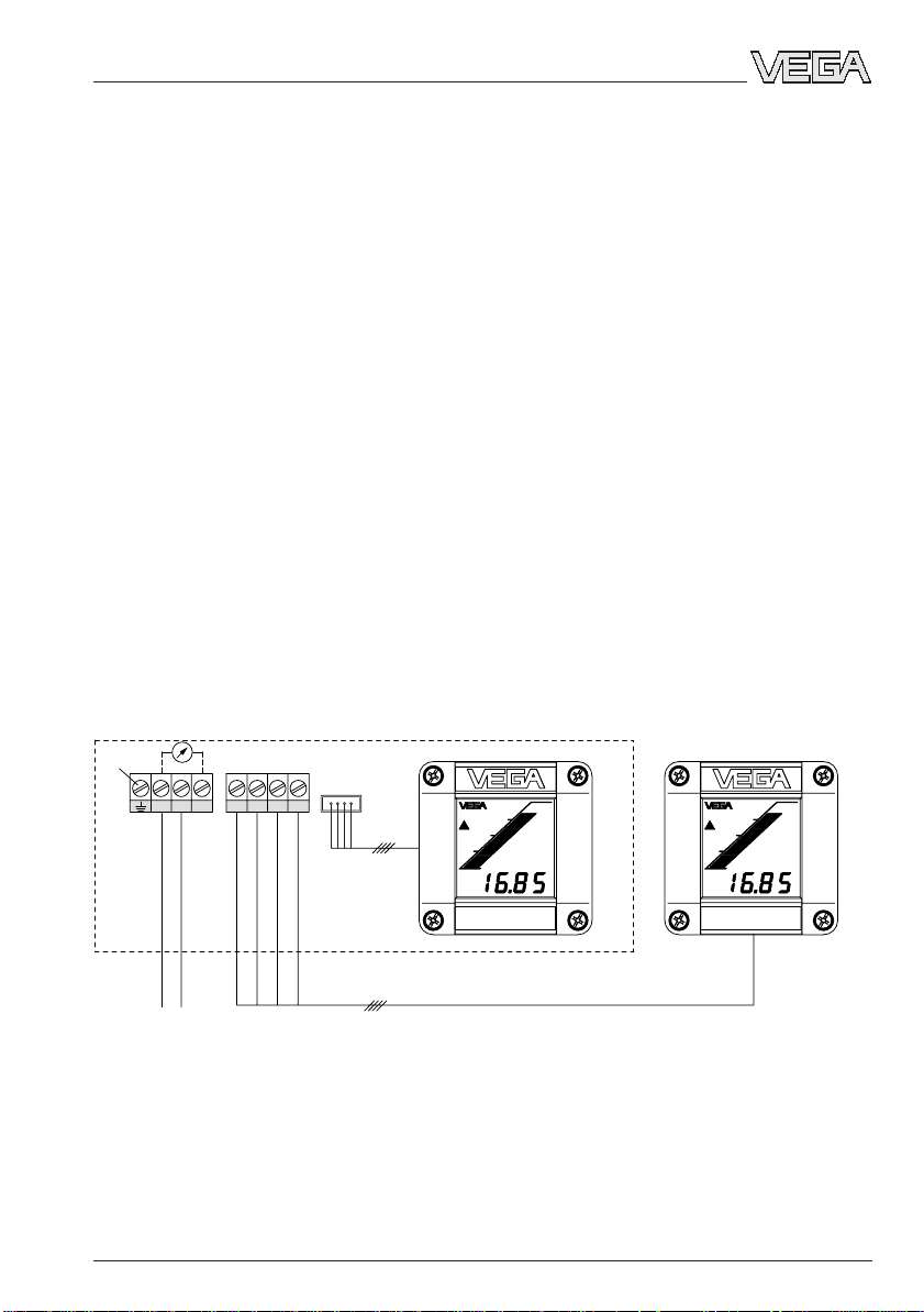
3.2 Connection diagram
Note:
An ammeter for local control of the output current can be connected to terminals 1 and 3. This
measurement can be made during operation without interrupting current on the supply cable.
VEGABAR with indicating module
Ammeter for local control
Function
1)
ground
Plug connection
321
8765
Indicating module
VEGADIS 10 with indicating
module
0 - 20 bar
–+
Supply voltage
12 … 36 V DC
4 … 20 mA
1)
If screened cable is used, the screening should be grounded in the terminal compartment and the ground
terminal on the outside of the housing must be grounded according to regulations. The terminals are
connected to each other in the housing.
VEGABAR 44 (HART®) 13
0 - 20 bar
Page 14

3.3 Connection examples
Supply via power supply unit
Processing is carried out using an indicating instrument.
Ammeter for local
control
+ – –
1 2 3
VEGABAR
terminals
Supply via a PLC with active input circuit
Processing is carried out via a PLC with active input circuit.
Ammeter for local
control
analogue / digital indicating instrument
Power supply unit
–
~
+
Electrical connection
+ – –
1 2 3
VEGABAR terminals
PLC
–
PLC
+
14 VEGABAR 44 (HART®)
Page 15

Setup
4 Setup
Electrical connection and setup can be simplified by temporarily mounting the cover or
the indicating module on VEGABAR laterally
or downwardly displaced.
VEGABAR
+ 4 ¼ 20 mA
12 ¼ 36 V DC E12
OK
87654321
-
DISPLAY
+
VEGADIS 10
Tighten screws lightly
Indicating module
4.1 Indicating module
Digital value
- 4 digits and decimal point
- basic function module: indicates a permanent bar measurement range
- menu-driven module: allows individual
scaling of bar measurement range
The connection is made via a plug connection
acc. to the scheme in the "Electrical connection“ section.
4.2 Setup with module "Adjustment
of the basic functions“
Adjustment elements
Rotary switch: Select requested
function
Key +: Change
OPERATE
t
i
ZERO
SPAN
Adjustment system
• Select the required function with the rotary
switch.
• Change the value with the "+“ and "–“ keys.
• Reset rotary switch to OPERATE, the ad-
justed values are transferred to the
EEPROM memory. They remain there even
in case of voltage drop.
Adjustment
For adjustment of zero and span, an ammeter must be connected to terminals 1 and 3.
The measured value is identical to the output
current.
value (increase
Key –: Change
value (decrease)
Tendency
indication
Bar graph
(e.g. process pressure zero or vessel
empty)
• Set rotary switch to zero.
• By pushing the "+“ and "–“ keys simultane-
ously, the current jumps directly to 4 mA or
1 Adjustment of zero
Digital value
set it to 4 mA by pushing the "+“ and "–“
keys.
Adjustment range of zero:
-20 % … +95 % of nominal measuring range
(corresponds to turn up of up to +95 %)
VEGABAR 44 (HART®) 15
Page 16

Setup
2 Adjustment of span
(e.g. process pressure or level at maximum)
• Set rotary switch to span.
• By pushing the "+“ and "–“ keys simultaneously, the current jumps directly to 20 mA
or set it to 20 mA by pushing the "+“ and "–
“ keys.
Adjustment range of span:
3.3 % … 120 % of the nominal measuring
range (corresponds to turn down 1 : 30)
Note:
- A modification of zero does not influence
the span, i.e. the final value of the measuring range will simply be shifted.
- It is also possible to adjust currents for
partial fillings or partial pressures, e.g.
8 mA for 25 % and 16 mA for 75 %. VEGABAR automatically calculates the current
values for 0 % or 100 % (only possible with
≥ 3.3 %).
Integration time
An integration time ti of 0 … 10 s can be adjusted for damping pressure shocks.
Procedure
• Set rotary switch to ti.
• By pushing the "–“ key 10 times, make
sure that the integration time is set to 0 s.
• Push the "+“ key once for every 1 s integration time required.
The integration time is the time required by
the current output signal to reach 90 % of the
actual level after a sudden change of the
process pressure.
16 VEGABAR 44 (HART®)
Page 17

Setup
4.3 Setup with module "Menu-driven adjustment with additional functions“
Adjustment elements
Display of:
- measured value
- functions in menu
▼ Jump to the menu below
with OK
▲ Jump to the menu above
with OK
Depending on parameter:
change value (increase) or
choose from list
+
OPERATE
3.00
mbar
Depending on parameter:
change value (decrease) or
choose from list
–>
OK
–
The adjustment with the multifunctional module is menu-orientated and is made via the
four keys in conjunction with the text display.
The move from the measured value indication
to the main menu is made with the "OK“ key.
Use the "→“ key to change within a menu
from one menu item to another.
Branching points
A branching point is shown by the ▼ symbol
and enables a jump to the menu below with
the "OK“ key. In this menu you can find parameters which are linked (possibly in other
submenus).
Choose menu item or interrupt
input
Acc. to the menu item, save the
adjusted value or change the menu
level
Reset
A reset is shown by the ▲ symbol and enables a jump back to the menu above with the
"OK“ key.
Automatic jump back to measured value
indication is triggered 60 minutes after the
last key push.
Parameters have no ▲ or ▼ symbol. The
value of the parameters can be modified with
the "+“ and "–“ keys or chosen from a list.
When these keys are pushed once, the value
flashes first. When pushed again, the value is
modified. The modified value can be saved
with the "OK“ key. Push the "→“ key to interrupt input (without storing the modification).
Certain parameters can be displayed but not
modified.
VEGABAR 44 (HART®) 17
Page 18

Menu schematic
Setup
Operate
0.2
mbar
Ad-
just-
ment
Adjust
with
press.
Measured value
indication
Calcu-
lation
ti
1
s
Adjust
without
press.
Unit
0.0
mbar
psi
kPa
Output
Unit
0.0
mbar
psi
kPa
%
Scal.
mA
Current
output
4-20mA
20-4mA
Scaling
indica-
tion
0%=
0
Fault
signal
22mA
Escape
3.6mA
Escape
The scaling can be carried out only if in the menu
item "unit“ the option "scal“ had been previously
chosen.
100%=
1000
Decimal
point
888.8
Escape
On sensors with a measuring range < 1 bar the unit
mbar
can be chosen instead of
Offset
correc-
tion
Offset
corr.
OK?
Zero
0.0
mbar
bar
Span
100.0
mbar
.
Escape
Escape
Simula-
tion
Sim.
xx.x
mbar
Sensor
unpres-
surized?
Zero
4.000
mA
Span
4.000
mA
Escape
18 VEGABAR 44 (HART®)
Page 19

Setup
Addi-
tional
funct.
Sensor
data
Escape
Lan-
guage
Lan-
guage
English
Reset
Reset
OK ?
Escape
Franc.
Ital.
Español
Deutsch
Fabr.-
Date
49.98
1)
The values indicated here (min. and max. values) can be set
to the present value by pushing the "+“ and "–“ keys simultaneously.
P min
-0.3
mbar
1)
Use the arrow key to move to the
right in the menu plan.
Reset
Now!
OK ?
P max
150
mbar
1) 1) 1)
Temp.
30.7
°C
T min
23.5
°C
T max
36.2
°C
Diagno-
stic no.
- - -
Escape
Adjust
with
press.
Escape
Scaling
indica-
tion
In the menu items with these symbols,
you can move to the top or bottom with
the "OK“ key.
Light grey menu items are only displayed if necessary (dependent on the
instrument version).
Span
100.0
mbar
Lan-
guage
English
Franc.
Ital.
Español
White letters indicate the parameters which
can be modified with the "+“ or "–“ key and
saved with the "OK“ key.
Sensor or measured value information which
cannot be modified in these positions are in
italics.
List
These options can be selected with the "+“ or
"–“ key and saved with the "OK“ key.
Deutsch
VEGABAR 44 (HART®) 19
Page 20

Setup
Adjustment taking the current pressure into account (live adjustment)
The live adjustment comprises two steps:
1 Adjustment of zero
2 Adjustment of span
The appropriate output current is displayed
via the DOT-matrix.
1 Adjustment of zero
(e.g. process pressure zero or vessel
empty)
Set the current value to 4.000 mA
Zero
4,000
with the "+“ or "–“ keys. Then push
mA
the "OK“ key.
2 Adjustment of span
(e.g. process pressure or level at maximum)
Set the current value to 20.000 mA.
Span
with the "+“ or "–“ keys. Then push
20,000
mA
the "OK“ key.
Note:
- A modification of zero does not influence
the adjusted span, i.e. the final value of the
measuring range will simply be shifted.
- Push "+“ and "-” simultaneously for standard adjustment of zero/span. The value
jumps directly to 4 mA/20 mA.
- In the case of a high turn down the "+“ and
"-“ key should generally be pressed simultaneously (due to resolution).
- By pushing the "+“ or "–“ keys individually,
the current output remains at the last value,
it takes on the adjusted value only after
storing with the "OK“ key.
- It is also possible to adjust currents for
partial fillings or partial pressures, e.g.
8 mA for 25 % and 16 mA for 75 %. VEGABAR automatically calculates the current
values for 0 % or 100 % (only possible with
a delta >3.3 %).
Adjustment without taking the current
pressure into account (dry adjustment)
Adjustment without pressure comprises four
steps:
1 Selection of the unit in which the adjustment
is to be carried out
2 Offset correction
3 Adjustment of zero
4 Adjustment of span
The offset correction (only in mode gauge
pressure) defines the reference position for
the measurement. It can be carried out:
- before or after the adjustment of zero and
span
- before or after installation of VEGABAR.
VEGABAR must be unpressurised for the
offset correction!
The adjustment without pressure can be
carried out with the sensor installed or not
installed (e.g. workroom). Any currently existing pressure has no effect on the adjustment.
1 Selection of the unit
Adjust
without
3 Adjustment of zero
mbar
4 Adjustment of span
Span
100,0
mbar
Choose the unit with the "+“ or "–“
key. Save the selected unit with the
press.
"OK“ key.
Unit
0.0
mbar
psi
kPa
Adjust zero with the "+“ or "–“ key
Zero
0,0
and save with the "OK“ key.
Adjust span with the "+“ or "–“ key
and save with the "OK“ key.
20 VEGABAR 44 (HART®)
Page 21

Setup
Note:
- A modification of zero does not influence
the adjusted span, i.e. the final value of the
measuring range will simply be shifted.
- By pushing the "+“ or "–“ keys individually,
the current output remains at the last value,
it takes on the adjusted value only after
storing with the "OK“ key.
Evaluation
Linearisation curve
Lin.-
Is only displayed if a linearisation
curve
curve had been activated with VVO.
active
Adjustment of the integration time
An integration time ti of 0 s … 10 s
ti
1
can be adjusted with the "+“ or "–“
s
saved with the "OK“ key.
Selection of the indicated unit
Scaling indication
key. The adjusted value can be
The actual measured pressure is
Unit
0.0
indicated in the DOT-matrix in the
mbar
measured value indication. The
psi
respective unit can be chosen with
kPa
the "+“ or "–“ key and the "OK“ key
%
Scal.
from a list. When choosing the unit
mA
"Scal.“, the following menu items are
available.
Bar graph and digital value relate to the adjusted measuring range and change in proportion to the current output. Digital values
< –10 % or > 110 % are shown as flashing
figures.
As a result of scaling, the 4 mA or 20 mA
user-specific current output values are
passed to the indicating module as 4-digit
digital values.
Outputs
Current output/Selection of the characteristics
The current output provides the actual measured pressure as an analogue current signal
4 … 20 mA relating to the adjustment.
Current
The characteristics can also be
output
4-20mA
20-4mA
Fault signal
If, during the continuous self-monitoring,
errors, damage or malfunctions in the measuring cell or the electronics are detected, a
fault signal is triggered via the current output.
inverted, e.g. switched to
20 … 4 mA with the "+“ or "–“ key
and the "OK“ key.
Fault
With "+“ or "–“ key and the "OK“
signal
key you can choose if the failure
22mA
3.6mA
current should be 22 mA or
3.6 mA.
In operating condition, the actual measured
Simulation
pressure is displayed on the indicating module:
- as bar graph with 20 segments
- as 4-digit digital value.
Scaling
indica-
tion
Simula-
You can set with the "+“ and "-“ key
tion
an individual pressure or % value to
check the outputs of VEGABAR
and connected components. The
Sim.
set value flashes during activated
xx.x
mbar
simulation. The simulation can be
stopped with the "OK“ key.
0%=
VEGABAR 44 (HART®) 21
100%=
0
1000
Decimal
point
888.8
Escape
Page 22

Setup
Additional functions
Sensor data
Important sensor data can be displayed via
the DOT-matrix for information and diagnostic
purposes:
- manufacturing date
- pointer function (p
- pointer function (p
- actual temperature value (Temp)
- pointer function (T
- pointer function (T
- diagnostic number
Addi-
tional
funct.
Sensor
data
Fabr.
P min
date
49.98
1)
The min. and max. values can be set to the actual
value by pushing the "+“ and "–“ keys simultaneously.
P max
-0.3
mbar
1)
1) 1) 1)
150
mbar
min
max
min
max
Temp.
)
)
)
)
30.7
°C
T min
23.5
°C
T max
36.2
°C
Diagnostic no.
- - -
Reset
The reset function deletes the ad-
Reset
justed values and resets all parameters to the default values. The
adjustment data again correspond
to the nominal measuring range.
Reset
OK ?
Reset
Now!
OK ?
4.4 Setup with adjustment software VEGA Visual Operating (VV O)
VVO-connection to the 4 … 20 mAcable
4 … 20 mA-cable with superimposed digital signal
–
~
+
Language
Lan-
VEGABAR comes adjusted to the
guage
language in which it is ordered.
VEGACONNECT 2
The languages German, English,
French, Italian or Spanish can be
Lan-
guage
English
Franc.
Ital.
Español
Deutsch
chosen with the "+“ or "–“ key and
the "OK“ key.
For connection of the PC to the sensor, a
VEGACONNECT 2 must be connected as
adapter between PC and 4 … 20 mA cable of
the sensor.
A digital signal is superimposed on the
4 … 20 mA output of the sensor. Please note
the internal resistance of the connected
evaluation system. If it is < 100 Ω (e.g. with a
power supply unit), the digital signal will be
damped. In this case, connect a load resistor
of R = 250 Ω into the 4 … 20 mA cable loop.
22 VEGABAR 44 (HART®)
Page 23

Setup
R = 250 Ω
VEGACONNECT 2
to the sensor
+
{
–
On analogue inputs of VEGA signal conditioning instruments or PLC systems, this
resistance is generally > 100 Ω, so that no
damping occurs.
Sensor configuration
Connect the PC via VEGACONNECT 2 directly to the sensor or to the 4 … 20 mAcable. Then start VVO. If the PC was connected with VVO already running, push the
function key F8 on the PC. Then your monitor
shows this picture "VEGA Visual Operating“.
For configuration of the sensor, first click to
Configuration, then to Measuring system.
Multidrop operation
VVO supports from version 2.60 the Multidrop operation of HART® sensors. Multidrop
means that the pressure transmitter always
consumes a supply current of 4 mA, independent of the pressure. The output signal is
not transmitted as usual via the current
strength but exclusively via a superimposed
digital signal. By means of this, up to 15
HART® sensors can be operated on only one
two-wire cable. Therefore it is necessary to
allocate in advance an address (1 ... 15) to
each individual sensor.
If you want to operate VEGABAR in Multidrop
mode, you have to click to the button Config-
ure mode in the window "Configuration measuring system“.
In the window "Configuration measuring system“ the menu language of VEGABAR can be
adjusted (only on VEGABAR with electronic
version "HL“). As measuring unit you can
choose bar, psi or kPa. By clicking Reset the
VEGABAR will be reset to default. Click to
Save, after you have made modifications.
With Quit you return to the window "VEGA
In the following window first choose Multid-
rop, then you can adjust the address and
click to OK.
Visual Operating“.
VEGABAR 44 (HART®) 23
Page 24

After this, several HART® sensors can be
connected to one common cable. The further
adjustments of VEGABAR in Multidrop operation (e.g. adjustment, measured value display) do not differ from the adjustments in
standard operation.
Setup
Sensor parameter adjustment –
Adjustment
Configuration measurement loop
Click to Configuration, point to Measurement loop, then click to Modify.
In the window "Configuration Measurement
loop Modify“ you can assign a name and a
description to the measurement loop. An
unambiguous name is important when you
adjust several sensors or measurement
loops with VVO. State under "Application“ if
you want to have a process pressure or level
measurement. With OK you again reach the
window "VEGA Visual Operating“. In the
following explanations we assume that you
have chosen the application "Process pressure measurement“. With the application
"Level measurement“ the adjustment deviates
slightly from the following demonstration.
Click to Instrument data, then to Parameter
adjustment.
Confirm this message with OK. Then the
window "Instrument data parameter adjustment“ appears.
From the window "Instrument data parameter
adjustment“ you reach all submenus of the
sensor. We recommend trying the individual
buttons one after the other. Then you always
reach this window. Click to the button Adjust-
ment to carry out the adjustment.
24 VEGABAR 44 (HART®)
Page 25

Setup
If you want to carry out the "Adjustment with
medium“ (live adjustment), click in this window to yes, then to OK.
Click to Zero or to Span to carry out the
appropriate adjustment.
In the window "Adjustment“ you click to Zero/
Span.
Then, in the window "Zero/Span adjustment“
you must choose the adjustment mode. If you
want to carry out the “adjustment without
taking the actual product into account” (dry
adjustment), click to no, then to OK.
Here you can choose in which unit the adjustment should be carried out (mbar, psi, kPa).
Then you enter in the appropriate fields the
pressure values corresponding to 0 % and
100 %. Then click to OK. The adjustment is
now carried out.
Note:
For the zero adjustment, the vessel or the
pressure lines must be unpressurised! For
the span adjustment you have to generate a
defined pressure (e.g. 80 %) in the vessel or
in the pressure lines.
In the window "Zero adjustment“ you choose
in which unit the adjustment should be carried out (mbar, psi, kPa). Click to Save. The
zero adjustment is then carried out.
VEGABAR 44 (HART®) 25
Page 26

Setup
In the window "Span adjustment“ you first
choose in which unit the adjustment should
be carried out (mbar, psi, kPa). Please state
if you want to edit the percentage value or the
current value. If you want to edit the percentage value, enter the value (e.g. 80 %) in the
field. Then click to Save. The span adjustment
is carried out.
Sensor parameter adjustment –
Linearisation curves
Click in the window "Instrument data parameter adjustment“ to Conditioning.
In the window "Linearisation“ you can choose
the linearisation curves of a horizontal cylindrical tank or a spherical tank. When choosing a user-programmable curve, you can
then click to Edit and start the program "Tank
Calculation“. With this program you can calculate the curves of different tank shapes
(see manual "VEGA Visual Operating“). After
selection of the curve, click to OK.
Sensor parameter adjustment –
Integration time
Click in the window "Instrument data parameter adjustment“ to Conditioning.
Click in the window "Conditioning“ to Lineari-
sation.
Click in the window "Conditioning“ to Integra-
tion time.
26 VEGABAR 44 (HART®)
Page 27

Setup
In the window "Integration time“ you can enter
a time of max. 10 seconds. Then click to OK.
Sensor parameter adjustment –
Outputs
Click in the window "Instrument data parameter adjustment“ to Outputs.
In the window "Current output“ you can set
the strength of the current in case of failure
(e.g. line break). Furthermore the current can
be inverted, i.e. at 0 % the current output is
20 mA, at 100 % 4 mA. Click to Save when
you have modified the adjustment.
Click in the window "Conditioning“ to Display
of measured value (only possible if you
have connected a display on VEGABAR).
In the window "Sensor-Display“ you choose
the parameter and the unit which the display
should indicate. If you choose "scaled“, you
can enter the figures corresponding to 0 %
and 100 %. Click to Save when you have
finished the adjustments in this window.
Click in the window "Conditioning“ to Current
output.
VEGABAR 44 (HART®) 27
Page 28

Setup
Sensor parameter adjustment – Offset
correction
Click in the window "Instrument data parameter adjustment“ to Additional Functions,
then in the window "Additional Functions“ to
Offset correction.
Confirm the question with OK, if the conditions are met.
Pointer function
Click in the window "Instrument data parameter adjustment“ to Meas. Loop Data.
In the window "Measurement loop data“ all
available actual sensor values and the peak
values (pointer function) will be displayed.
With the button reset you can set all indicated peak values simultaneously to the
actual value.
Click in the window "Offset correction“ to
Correct.
28 VEGABAR 44 (HART®)
Page 29

Setup
Simulation
Pressure can be simulated to check the
outputs of VEGABAR and connected instruments or components. To do this, click to
Diagnosis, then to Simulation.
In the window "Simulation of outputs“ click to
Start to start the simulation. With the buttons
"<–“ and "–>“ (or with the horizontal scroll bar
between) you can adjust values between
-10 % and 110 %. Click to Stop to end the
simulation.
Display of measured value
The actual values of the measurement loops
can be displayed from the main menu. Click
DisplayDisplay
to
Display, then to
DisplayDisplay
valuevalue
value.
valuevalue
In the window "Display of measured value“
you can choose the unit in which the measured value is indicated. Furthermore you see
the current value. By clicking to Quit you
return to the window "VEGA Visual Operating“.
Display of measurDisplay of measur
Display of measur
Display of measurDisplay of measur
eded
ed
eded
Note:
The simulation mode is not stopped automatically, but remains active until you switch it off!
VEGABAR 44 (HART®) 29
Page 30

Setup
4.5 Setup with HART® handheld
With any HART® handheld you can set up
VEGABAR 44 like all other HART® compatible
sensors. A special DD (Device Description)
is not necessary. Just connect the HART
handheld to the sensor signal cable after you
have connected the sensor to supply voltage.
®
250 Ω
Note:
If the resistance of the signal circuit is less
than 200 Ω, a resistor of 250 … 350 Ω must
be looped into the signal/connection line
during adjustment. The digital adjustment
and communication signals would otherwise
be short-circuited through insufficient resistance of e.g. the supply voltage source or the
processing system. In such case, communication with the sensor would not be assured.
Simply connect the adjustment resistor in
parallel to the connection socket of the HART
handheld (see figure).
+
–
Ri < 200 Ω
®
30 VEGABAR 44 (HART®)
Page 31

Setup
The most important adjustment steps
On the following four pages you see a menu
schematic of the HART® handheld in conjunction with VEGABAR process pressure transmitters. The most important adjustment steps
are marked in the menu schematic with the
letters A … E. If you are not familiar with
HART® handheld, please note: For the parameter adjustment, first push the "
key. The adjustment is saved in the handheld, but not in the sensor itself.
Generic: SENSOR
PV URV
100.0 mbar
90.3 mbar
HELP DEL ESC EN TER
After you have pushed "
push "
SEND
“ (here in the example for the
ENTER
min. adjustment).
Generic: SENSOR
1 PV LRV bar
2 PV URV bar
HELP SEND H O ME
ENTER
“
4.2
(5.2)
“, you have to
Push "OK“ and the adjustment is now transferred to the sensor. After a short moment,
you are asked to switch the system from
manual to automatic operation. Confirm with
"OK“.
Generic: SENSOR
– WARNING –
Return control loop
to automatic control
OK
You now see the adjustment that was made.
Generic: SENSOR
1 PV LRV bar
2 PV URV bar
HELP HOME
After pushing "
SEND
“, a warning is displayed
that you are about to change device output
and for safety reasons you should switch
your system to manual operation.
Generic: SENSOR
– WARNING –
Pressing "OK“ will
change device output.
Put loop in manual.
ABORT OK
VEGABAR 44 (HART®) 31
Page 32

HART® menu schematic
Switch on:
Hart Communicator
Self T est
in Progress
Firmware Rev: F2.2
Module Rev: 3.6
01992-96 FRSI
after approx.
20 s
Generic: SENSOR
Online(Generic)
1 Device setup
2 PV 80.945 mbar
3 PV AO mA
4 PV LRV bar
5 PV URV bar
SAVE
Set up the sensor in the sequence of the
letters A, B, C and D (adjustment without
medium).
For the adjustment with medium you
setup the sensor in the sequence A1, B1,
C and D.
Generic: SENSOR
Device setup
1 Process variables
2 Diag/Service
3 Basic setup
4 Detailed setup
5 Review
SAVE HOME
Generic: SENSOR
PV
80.945 mbar
HELP EXIT
Generic: SENSOR
AO1
16.952 mA
HELP EXIT
1
2
3
Generic: SENSOR
Process variables
1 Snsr 80.945 mbar
2 AI % rnge
3 AO1 mA
HELP SAVE HOME
Generic: SENSOR
1 PV LRV bar
2 PV URV bar
HELP HOME
Generic: SENSOR
– WARNING –
Return control loop
to automatic control
Generic: SENSOR
– WARNING –
Pressing "OK“ will
change device output.
Put loop in manual.
ABORT O K
Generic: SENSOR
1 PV LRV bar
2 PV URV bar
Setup
1.1
OK
HELP SEND HOME
4.1
(5.1)
4.2
(5.2)
Important and
required
menu windows
Less important
menu windows
Not required, unimportant
or blocked menu windows
Generic: SENSOR
1 PV LRV bar
2 PV URV bar
HELP HOME
Generic: SENSOR
1 PV LRV bar
2 PV URV bar
HELP HOME
continue like under 4
Generic: SENSOR
PV LRV
4
A
B
5
0.000 mbar
10.000 mbar
HEL P D EL ESC ENTER
Empty adjustment without
medium
Generic: SENSOR
PV URV
100.000 mbar
90.300 mbar
HELP DEL ESC ENTER
Full adjustment without
medium
continue like under
A figure 4.1(5.1)
32 VEGABAR 44 (HART®)
Page 33

Setup
Generic: SENSOR
PV
80.945 mbar
HELP EXIT
Generic: SENSOR
PV % rnge
80.945 %
HELP EXIT
Generic: SENSOR
AO1
16.952 mA
HELP EXIT
Generic: SENSOR
Diag/Service
1 Test de vice
2 Loop test
3 Calibration
4 D/A trim
SAVE HOME
Generic: SENSOR
Basic setup
1Tag
2 PV Unit
3 Range values
4 Device information
5 PV Xfer fnctn
HELP SAVE HOME
6 PV Damp
1.1.1
Safety
enquiry
Acknowledge
1.1.2
1.1.3
1.2
Blocked menu. The
following menu window is
indicated but not supported
by the sensor. Therefore
saving of adjustments
carried out here is not
possible.
1.3
T r ansmission function
(linear)
Generic: SENSOR
Choose analog output
level
14 mA
2 20 mA
3 Other
4End
Generic: SENSOR
Calibration
HELP SAVE HOM E
ABORT ENTER
1 Apply values
2 Enter values
D
C
HELP HOME
Generic: SENSOR
Tag
SENSOR
SENSOR
HE LP DEL ESC ENTER
Generic: SENSOR
PV Snsr unit
bar
mbar
g/cm2
kg/cm2
Pa
Generic: SENSOR
Range values
1 PV LRV bar
2 PV URV bar
3 PV LSL bar
4 PV USL bar
Generic: SENSOR
Device information
1 Distributor
2 Model
3 Dev id
4Tag
5 Date 10/01/97
HELP SAVE HOME
6 Write protect None
7 Descriptor
8 Message
9 PV Snsr s/n
Final asmbly num 0
Revision #´s
Generic: SENSOR
PV Damp
1.000 s
2 .000 s
1.2.2
Input of individual current
values for test purposes
(simulation of measured
value)
1.2.3
A1
B1
1.3.1
1.3.2
ESC ENT E R
1.3.3
1.3.4
1.3.6
Empty and full
adjustment
with medium
}
(see next page)
Newly assigned
measurement loop
designation to be
saved with ENTER
and SEND
see next
page
}
see next
page
}
HELP DEL ESC EN TER
Generic: SENSOR
Review
Model
Generic
HELP PREV
NEXT EXI T
1.5
Generic: SENSOR
Detailed setup
1 Sensors
2 Signal condition
3 Output condition
4 Device information
SAVE HOME
1.4
}
see next
page
VEGABAR 44 (HART®) 33
Page 34

Setup
HART® menu schematic (continuation)
Generic: SENSOR
Calibration
1 Apply values
2 Enter values
HELP SAVE HOME
Generic: SENSOR
Range values
1 PV LRV bar
2 PV URV bar
3 PV LSL bar
4 PV USL bar
HELP HOME
Generic: SENSOR
Device information
1 Distributor
2 Model
3Dev id
4Tag
5 Date 10/01/97
HELP SAVE HOME
6 Write protect None
7 Descriptor
8 Message
9 PV Snsr s/n
Final asmbly num 0
Revision #´s
Generic: SENSOR
Detailed setup
1 Sensors
2 Signal condition
3 Output condition
4 Device information
SAVE HOME
1.2.3
1.2.3.1
Generic: SENSOR
Enter values
1 PV LRV bar
2 PV URV bar
3 PV USL bar
4 PV ´LSL bar
HELP HOME
1.3.3
Indication of the
}
sensor measuring
range limits
Menu fields (broken line:
Repetition of previous page
1.3.4
Unknown Enumerator
General
(1.3.4.3) Indication of the sensor serial number
individual text adjustment
Indication of the sensor serial number (as menu window 1.3.4.3)
1.4
like menu 1.3.4
Safety
enquiry
Acknowledge
(1.3.4.4) Measurement loop designation as under menu window 1.3.1
(1.3.4.5) Date adjustment
None
individual text adjustment
Generic: SENSOR
Sensors
1 PV 80.945 mbar
2 PV Snsr unit bar
3 Sensor information
HELP SAVE HOME
Generic: SENSOR
Signal condition
1 Snsr Damp 1.000 s
2 AI URV
3AI LRV
4 Xfer fnctn
5 % rnge
HELP SAVE HOME
Generic: SENSOR
Output condition
1 Analog output
2 HART output
Generic: SENSOR
Set the:
14mA
2 20mA
3Exit
ABORT ENTER
1.2.3.2
like display 4.1
like display 4.2
Indication of the
}
sensor measuring
range limits
Generic: SENSOR
PV LRV
0.000 mbar
10.000 mbar
HELP DEL ESC ENTER
Generic: SENSOR
PV URV
100.000 mbar
90.300 mbar
HELP DEL ESC ENTER
Empty adjustment with
medium
1.2.3.1
Generic: SENSOR
Apply new 4 ma input
A1
Generic: SENSOR
Apply new 20 ma input
B1
1.3.3.1
1.4.1
Measured value
Modification of the unit
Info on lower and upper
measuring range limit as well
as min. span (also the sensor
1.4.2
characteristics values)
Adjustment of the integration time
Adjustment of zero and span
Adjustment of zero and span
linear
Indication of the level in % of the
adjusted span
1.4.3
Full adjustment with
medium
1.3.3.2
ABORT OK
ABORT OK
SAVE HOME
34 VEGABAR 44 (HART®)
Page 35

Setup
Generic: SENSOR
Current applied
process value :10.945 mbar
1 Set as 4 mA value
2 Read new value
3 Leave as found
ABORT ENTER
Generic: SENSOR
Current applied
process value:
85.281 mbar
1 Set as 20 mA value
2 Read new value
3 Leave as found
ABORTENTER
Generic: SENSOR
Analog output
1 AO1 13.467mA
2 AO Alrm typ Lo
3 Loop test
4 D/A trim
5 Scaled D/A trim
HELP SAVE HOME
1.2.3.1.1
1.2.3.1.2
1.4.3.1
Generic: SENSOR
Set the :
14 mA
2 20 mA
3Exit
ABORT EN TER
Generic: SENSOR
Ser the:
14 mA
2 20 mA
3Exit
Generic: SENSOR
AO Alrm typ
Lo
Generic: SENSOR
WARN-Loop should be
removed from
automatic control
Menu windows are displayed but not
}
supported by the sensor.
Saving of adjustments carried out here is
therefore not possible.
1.2.3.1.1.1
ABORT ENTER
1.2.3.1.2.1
1.4.3.1.2
EXIT
1.4.3.1.3
ABORT O K
Generic: SENSOR
Apply new 4 ma input
ABORT OK
Generic: SENSOR
Apply new 20 ma input
ABORT OK
Low: I n case of failure, current output
goes to 22 mA
High: In case of failure, current output
goes to < 3.6 mA
Generic: SENSOR
Choose analog output
level
14 mA
2 20 mA
3 Other
4End
ABORT ENTER
1.4.3.1.3
Generic: SENSOR
Current applied
process value:
10.945mbar
Generic: SENSOR
Current applied
process value:
85.281 mbar
Generic: SENSOR
Fld dev output is
fixed at 4.000 mA
1 Set as 4 mA value
2 Read new value
3 Leave as found
ABORT ENTER
1 Set as 20 mA value
2 Read new value
3 Leave as found
ABORT ENTER
1.4.3.1.3.1
ABORT O K
1.4.3.2.3
ESC ENTER
1.4.3.2.4
Off
On
Not used
Non
Unused
Special
Leave the Burst-mode in
OFF-position
Choice is not supported
Sensor signals measured values only on
request
Sensor signals measured values
unrequested
Choice is not supported
Generic: SENSOR
HART output
1 Poll addr
2 Num req preams 0
3 Burst mode Off
4 Burst option
HELP SAVE HOME
Generic: SENSOR
Burst mode
Off
On
Not used
None
Unknown
1.4.3.2
Generic: SENSOR
Burst option
*************
PV
% range/current
Process vars/crnt
HELP ESC ENTER
Note:
After adjustment of a parameter, push "ENTER“ and then "SEND“.
Confirm the message to switch over to manual operation with "OK“.
Confirm the message to reset to automatic operation also with "OK“.
Only then will the adjustment be stored in the sensor and take effect.
VEGABAR 44 (HART®) 35
Page 36

5 Diagnostics
Diagnostics
5.1 Maintenance
VEGABAR process pressure transmitters are
maintenance-free.
5.2 Failure rectification
Fault signals
VEGABAR provides maximum reliability with
its self-test and continuous self-monitoring.
VEGABAR diagnostics distinguishes between
atypical process conditions and faults in the
VEGABAR.
Atypical process conditions
Exceeding or falling short of measuring
range limits (fault signal extinguishes when
the measured value is again in the measuring
range).
Failure in VEGABAR
Failure in the electronics, interference or
damage to the measuring cell.
The following table assists in analysis of fault
signals.
Reason Fault signal via
Clearly "OPERATE Bar graph 0 %
outside ???? or 100 % Current
measuring bar“ digital value value
range flashes 3.6 mA
Overload Bar graph 0 %
range or 100 %,
of the digital value, four
meas. cell flashing seg-
Failure in all segments
VEGABAR flash
DOT-matrix Bar graph Current
Digital indication output
or
22 mA
ments "- - - -“
On instruments with menu-driven adjustment
with additional functions, the possible reasons are displayed under the menu item
"Diagnostics no.“.
Diagnostics no. Meaning
1 Connection to CID converter inter-
rupted
2 Frequency signal of the capacitor not
within the limit values
3 Frequency signal of the reference
capacitor not within the limit values
4 Frequency signal temperature not
within the limit values
7 Communication error to EEPROM
9 Error in EEPROM CRC-checksum
11 Process fitting or electronics unit has
been exchanged (appears for approx.
20 s after switching on for the first
time after the exchange)
Troubleshooting
If the displayed value does not correspond
to the level in the vessel or to the process
pressure, the following measures must be
taken:
- check the pressure compensation (only
with gauge pressure measuring ranges)
- check the electrical connection.
36 VEGABAR 44 (HART®)
Page 37

Diagnostics
Checking pressure compensation
Open the housing of VEGABAR. The measured value must not change. However, if the
displayed value changes, compensation of
the atmospheric pressure is not ensured,
which will lead to distortion of the measured
value. Check the breather on the VEGABAR
housing.
Checking the electrical components
–+
1 2 3
mA
–
Voltage
V
Ammeter for local
control
Current
mA
External
energy source
–
~
+
Voltage
- the terminal voltage on VEGABAR must be
at least 12 V DC
Current
Current value Condition
3.8 … 20.5 mA standard range for the output
0 mA signal cable interrupted
< 3.6 mA sensor electronics or pressure
22 mA sensor electronics or pressure
current
sensor element defective
sensor element defective
VEGABAR 44 (HART®) 37
Page 38

6 Instrument modification
Instrument modification
6.1 Exchange of adjustment modules
Display
module
Module for
basic
functions
Module for
menu-driven
adjustment
Module
without
adjustment
Exchange of the adjustment module
Removal of the adjustment module
• Separate VEGABAR from the power
supply
• Loosen the screws on the upper side of
the housing and remove the cover or the
display module
• Loosen connection cables from the terminals, if necessary pull out the plug connection of the display module
• Loosen the two screws of the adjustment
module
• Remove adjustment module and pull out
the plug connection
Insertion of an adjustment module
• Plug the plug connection of the new adjustment module into the plug-in socket of
the sensor electronics
• Fasten the new adjustment module
• Reconnect the connection cables, if necessary, also the cable from the display
module
• Close cover or display module of VEGABAR
• Reconnect VEGABAR to power supply
VEGABAR
The modular construction of VEGABAR allows
retrofitting, interchange or removal of the
adjustment and display modules. Data previously saved (e.g. adjustment values) are not
stored in the adjustment module but in an
EEPROM of the electronics module and
therefore readjustment is not necessary. The
connection of the modules is made via a 4pole plug connection.
38 VEGABAR 44 (HART®)
Page 39

Instrument modification
6.2 Exchange of electronics
You first have to remove the adjustment module, as described in chapter "6.1 Exchange
of adjustment modules“, in order to exchange
the complete electronic module of VEGABAR.
Ground
screw
Fixing screw
Fixing screw
Note:
No new adjustment is necessary after
exchanging the electronics module. When
switching on (connection of supply voltage)
for the first time after exchange of the electronic unit, it takes approx. 20 s until the
actual measured value is displayed.
Plug
connection
• Remove the ground screw and the two
smaller fixing screws connecting the electronic unit with the housing
• Pull the electronic unit to the top and pull
out the plug connection
• Proceed in reverse sequence when installing the new electronics module
VEGABAR 44 (HART®) 39
Page 40

Instrument modification
6.3 Exchange of the hygienic form seal on VEGABAR 44
On the VEGABAR 44 process pressure
transmitter with hygienic fitting LA or LB, the
ceramic measuring cell is sealed by a
gapless, radial form seal. This form seal
(material EPDM-FDA 1) approved) can be
exchanged by the user without readjustment
being necessary. The criteria and time periods for such an exchange are determined by
process conditions and hygienic requirements.
Important:
Only use the original VEGA replacement part,
article no. 2.17 775 as seal ring!
Note the following procedure when exchanging the seal.
Removal procedure:
1 Pressure transmitter should be unpres-
surized (switch off process pressure or
empty vessel).
2 Loosen the hexagon head screw (46 mm
across flats) (1) by turning counterclockwise
Installation procedure:
6 Pull a new form seal (5) over the measur-
ing cell (the conical side should point
towards the process connection!).
7 Insert the pressure transmitter carefully
into the process connection by turning
clockwise.
8 Tighten hexagon head screw (46 mm) (1)
to its fixed position (45 Nm).
9 Rotate the housing (4) of the pressure
transmitter to its original position
Exchange of the form seal is now finished.
Ensure proper disposal of the removed seal.
Note!
The process connection (2) (i.e. sleeve nut)
must not be loosened!
3 Completely loosen the compression
screw (hex head) and remove the pressure transmitter from the process connection
Note:
Should the pressure transmitter turn by loosening the pressure screw, it can be held by
the adapter (3) with a wrench (36 mm across
flats).
1 Hexagon compression screw
2 Process connection
3 Adapter
4 Housing
5 Form seal
4 Slightly lift the form seal (5) (with a knife
or similar utensil) and loosen it from the
ceramic measuring cell
5 If the form seal (5) does not completely
surround the measuring cell, it should be
carefully removed from the process connection.
1)
Food and Drugs Administration
40 VEGABAR 44 (HART®)
Page 41

Notes
VEGABAR 44 (HART®) 41
Page 42

Notes
42 VEGABAR 44 (HART®)
Page 43

Notes
VEGABAR 44 (HART®) 43
Page 44

VEGA Grieshaber KG
Am Hohenstein 113
D-77761 Schiltach
Germany
Phone +49 (0) 7836 50-0
Fax +49 (0) 7836 50-201
E-Mail info@de.vega.com
www.vega.com
ISO 9001
The statements on types, application, use and operating conditions of
the sensors and processing systems correspond to the latest information at the time of printing.
Technical data subject to alterations
24411-EN-021218
 Loading...