

Page 1
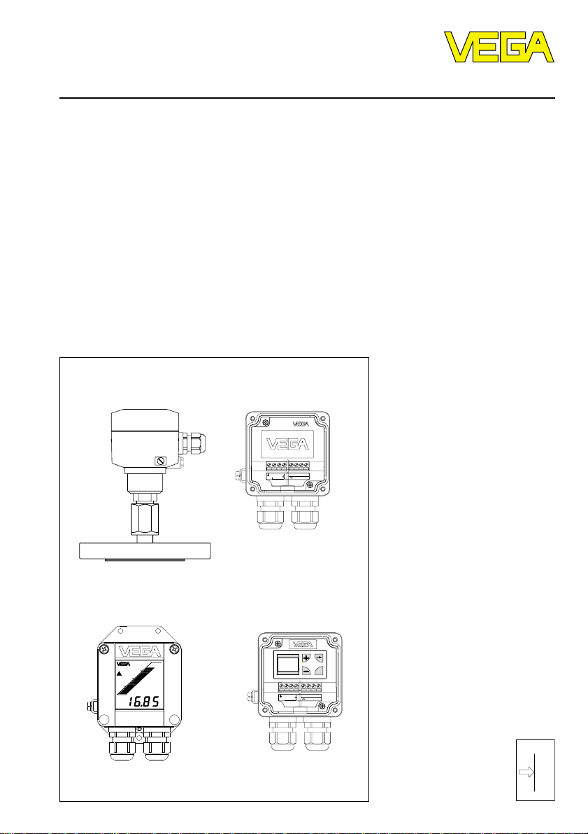
Operating Instructions
VEGABAR 21
87654321
+ -
-
DISPLAY
4 ¼ 20 mA
+
VEGADIS 10
12 ¼ 36 V DC E12
Level and Pressure
+ 4 … 20 mA
12 … 36 V DC E12
+
DISPLAY
VEGADIS 10
OK
87654321
p
Page 2

Safety information
Safety information
The described module must only be installed
and operated as described in these operating
instructions. Please note that other action can
cause damage for which VEGA does not take
responsibility.
2 VEGABAR 21
Note Ex-area
Please note the approval documents attached
(yellow binder), and especially the included
safety data sheet.
Page 3

Contents
Contents
Safety information ........................................................................ 2
Note Ex-area ................................................................................ 2
1 Product description
1.1 Function and configuration .................................................. 4
1.2 Self-monitoring ..................................................................... 4
1.3 Technical data ....................................................................... 5
1.4 Approvals and certificates ................................................ 10
1.5 Dimensions ......................................................................... 10
2 Mounting................................................................................... 13
3 Electrical connection
3.1 Connection information ...................................................... 13
3.2 Connection plan ................................................................. 14
3.3 Connection examples ........................................................ 15
4 Set-up
4.1 Adjustment of the basic functions .................................... 16
4.2 Menu-guided adjustment with additional functions ......... 17
4.5 Indicating module ............................................................... 22
5 Diagnosis
5.1 Maintenance ....................................................................... 23
5.2 Failure removal ................................................................... 23
6 Instrument modification
6.1 Interchanging adjustment modules .................................. 25
7 Measurement with isolating systems ................................. 26
VEGABAR 21 3
Page 4

1 Product description
Product description
1.1 Function and configuration
VEGABAR 21 is an efficient pressure transmitter with isolating system for process pressure measurement and hydrostatic level
measurement. The hydrostatic pressure of
the medium acts on the separating diaphragm of the isolating system and is transferred via the isolating liquid to a ceramiccapacitive measuring cell CERTEC®. The
pressure on this measuring cell effects a
capacitance change within the measuring
cell. This capacitance change is detected by
an ASIC (Application specific integrated
circuit) and converted by an integral oscillator with microcomputer into a pressure proportional signal. The exact, digital processing
of measured data with highest resolution
ensures perfect technical data.
Isolating systems are used to protect the
measuring cell against aggressive products
and high temperatures. Due to the suitable
selection of isolating liquid and diaphragm
material, systems with a temperature resistance up to 400°C are possible.
The oscillator is powered by a separate
VEGA-signal conditioning instrument, a stabilised power supply unit or a DCS (active
input). After the adjustment, a standardised
current signal 4 … 20 mA is available which
can be displayed (e.g. in DCS-systems) or
further processed.
1.2 Self-monitoring
Important electronics components are
checked on their function and internal parameters such as sensor value, temperature and
operating voltage are monitored to increase
the reliability.
VEGABAR 21 with ceramic CERTEC®-measuring cell offers the advantage of a continuous self-monitoring. Measuring and reference
capacitance of the measuring cell are in a
defined relation over the complete measuring
range. Each deviation from these data is a
reliable indicator for a malfunction of the
measuring cell.
If during these routines failures or malfunctions are detected, a fault signal is triggered
via the 4 … 20 mA-output (current jump to
3,6 mA or 22 mA).
Two versions are available for adjustment:
- adjustment module directly on VEGABAR
- adjustment module in external housing
(VEGADIS 10)
4 VEGABAR 21
Page 5

Product description
1.3 Technical data
Mechanical data
Materials, wetted parts
Process connection stainless steel 1.4571
Diaphragm stainless steel 1.4571, Hastelloy C276 or B2,
Extension stainless steel 1.4571
Materials, non-wetted parts
Housing high resistance plastic PBT (Polyester)
Earth terminal stainless steel 1.4305
Window of the indicating module Lexan
Weight
VEGABAR approx. 0,8 … 8 kg
Adjustment and indicating elements
Adjustment of the basic functions 2 keys, 1 rotating switch
Menu-guided adjustment with
additional function
- adjustment elements 4 keys
- indicating elements DOT-Matrix display, 3 lines with 7 figures each
Indicating module LC-display with
Monel 400, Tantalum, PTFE-foil on 1.4571
(dependent on the isolating system)
- bargraph (20 segments)
- digital value (4-digit)
- tendency indicators for raising or falling
values
Electrical data
Connection
Cable entry M20 x 1,5 (for cable-ø 5 … 9 mm)
Screw terminals for cross-section area of conductor up to
Protective measures
Protection
1)
Protection class III
Overvoltage category III
1)
For maintaining the housing protection, the use of the suitable seal for the cable in the Pg is necessary. If
the used seal does not fit with the cable, it should be replaced by a suitable one.
VEGABAR 21 5
2,5 mm
IP 65
2
Page 6
Product description
Supply and signal circuit
Supply voltage 12 … 36 V DC
Permissible residual ripple USS £ 1 V
Output signal
- range 3,8 … 20,5 mA
- resolution 6 µA
Current limitation 22 mA
Fault signal 22 mA (3,6 mA)
Integration time 0 … 10 s adjustable
Average delay time 70 ms
Connection line 2-wire
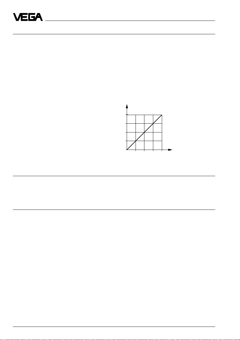
Max. permissible load dependent on the supply voltage
(see load diagram)
1000
750
in Ohm
total
500
250
Load RL
0
12
18 24 30 36
Voltage of the external energy UH in Volts
Indicating and adjustment circuit
For connection to VEGADIS 10 and/or the indicating module
Data transmission digitally
Connection line 4-wire
Max. line length 25 m
Adjustment ranges
Zero -20 % … +95 % adjustable of nominal range
Span 3,3 % … 120 % adjustable of nominal range
Recommended turn down:
- accuracy class 0,25 up to 1 : 5
- accuracy class 0,1 up to 1 : 10
6 VEGABAR 21
Page 7
Product description
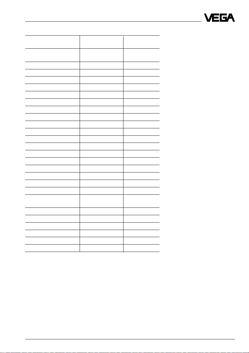
Measuring ranges
Nominal measuring Gauge pressure Low pressure
range resistance
1)
resistance
Relative pressure
0 … 0,4 bar 20 bar -0,4 bar
0 … 1,0 bar 25 bar -1,0 bar
0 … 2,5 bar 35 bar -1,0 bar
0 … 5,0 bar 45 bar -1,0 bar
0 … 10,0 bar 60 bar -1,0 bar
0 … 20,0 bar 90 bar -1,0 bar
0 … 40,0 bar 140 bar -1,0 bar
0 … 60,0 bar 200 bar -1,0 bar
-0,05 … 0,05 bar 10 bar -0,1 bar
-0,1 … +0,1 bar 15 bar -0,2 bar
-0,2 … +0,2 bar 20 bar -0,4 bar
-0,5 … +0,5 bar 25 bar -1,0 bar
-1,0 … +0,0 bar 25 bar -1,0 bar
-1,0 … +1,5 bar 35 bar -1,0 bar
-1,0 … +4,0 bar 45 bar -1,0 bar
-1,0 … +10,0 bar 60 bar -1,0 bar
-1,0 … +20,0 bar 90 bar -1,0 bar
-1,0 … +40,0 bar 140 bar -1,0 bar
-1,0 … +60,0 bar 200 bar -1,0 bar
Absolute pressure
0 … 1,0 bar 25 bar
0 … 2,5 bar 35 bar
0 … 5,0 bar 45 bar
0 … 10,0 bar 60 bar
0 … 20,0 bar 90 bar
0 … 40,0 bar 140 bar
0 … 60,0 bar 200 bar
1)
Note the nominal pressure of the process connection!
VEGABAR 21 7
Page 8

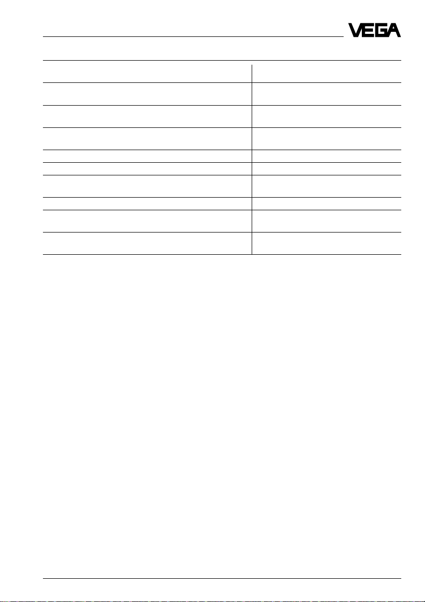
Accuracy (similar to DIN 16 086, DIN V 19 259 - 1 and IEC 770)
Influence of the ambient temperature
Average temperature coefficient
of the zero signal
- accuracy class 0,25 < 0,15 %/10 K
- accuracy class 0,1 < 0,05 %/10 K
1) 2)
Product description
Long-term stability
Long-term drift of the zero signal
1) 3)
< 0,1 % (meas. cell, without considering the
isolating system)
Deviation
Reference conditions (acc. to IEC 770)
- temperature 15°C … 35°C
- rel. humidity 45 % … 75 %
- air pressure 860 mbar … 1060 mbar
Determination of characteristics limit point adjustment acc. to DIN 16 086
Characteristics linear
Deviation in characteristics
1)
- accuracy class 0,25 < 0,25 %
- accuracy class 0,1 < 0,1 %
Hysteresis
Repeatability
1)
1)
< 0,02 %
< 0,02 %
Other actuating variables
Calibration position standing, diaphragm points downwards
Vibration resistance mechanical vibrations with 4 g and
5 … 100 Hz, tested acc. to the regulations of
German Lloyd GL-characteristics 2
Operating conditions
Ambient conditions
Ambient temperature -40°C … +85°C
- indication module -20°C … +70°C
Storage and transport temperature -40°C … +85°C
Medium temperature -40°C … +100°C
Medium temperature, abhängig von
Druckmittlerflüssigkeit Temperature
- silicone oil -40°C … +130°C / -40°C … +130°C
- silicone oil and cooling element -40°C … +200°C / -40°C … +130°C
- silicone oil and capillaries 1 m -40°C … +200°C / -40°C … +130°C
- vegetable oil -10°C … +130°C / -10°C … +130°C
- vegetalble oil and cooling element -10°C … +250°C / -10°C … +130°C
- high temperature oil a. cooling element -10°C … +400°C / -10°C … +200°C
- high temperature oil and capillaries 1 m -10°C … +400°C / -10°C … +200°C
1)
Relating to the nominal range.
2)
In the compensated temperature range of 0°C … +80°C, reference temperature 20°C. Without isolating
diaphragm, capillaries, cooling element (see influence of the ambient temperature).
3)
Acc. to IEC 770, item 6.1.2 relating to the nominal range.
4)
At pabs < 1 bar (vacuum range ) the isolating liquid boils already at low temperatures.
8 VEGABAR 21
p
> 1 bar / p
abs
4) < 1 bar
abs
Page 9
Product description
Zusätzlicher Temperatureinfluß durch Druckmittler
Process connection Temperature coefficient
[mbar/10 K]
FA Flange DN 25 PN 40 acc. to DIN 2501,
seal surface acc. to DIN 2526 Form D 1,8
FB Flange DN 40 PN 40 acc. to DIN 2501,
seal surface acc. to DIN 2526 Form D 1,0
FC Flange DN 50 PN 40 acc. to DIN 2501,
seal surface acc. to DIN 2526 Form D 2,0
FE Flange DN 50 PN 40 with ext. 100 mm 1,9
FG Flange DN 50 PN 40 with ext. 200 mm 2,1
FH Flange DN 80 PN 40 acc. to DIN 2501,
seal surface acc. to DIN 2526 Form D 0,4
FK Flange DN 80 PN 40 with ext. 100 mm 0,5
FN Flange DN 1" 300 lbs acc. to ANSI B 16.5,
seal surface RF 1,8
FO Flange DN 2" 600 lbs acc. to ANSI B 16.5,
seal surface RF 2,0
- by cooling elements,
dependent on diaphragm-ø 0,1 … 1,5 mbar/10 K
- by 1 m capillary line
dependent on diaphragm-ø 0,1 … 15 mbar/10 K
VEGABAR 21 9
Page 10

Product description
1.4 Approvals and certificates
Approvals
Ex Zone 2
StEx Zone 10
Ship approval
CENELEC EEx ia IIC
ATEX II 1G EEx ia IIC and WHG
ATEX II 1G EEX ia IIC and ship approval
If for certain applications the use of approved instruments is required, the appropriate legal
documents (test reports, test certificates and conformity certificates) have to be noted.
These are supplied with the appropriate instrument.
CE-conformity
VEGABAR 21 corresponds to the requirements of EMC (89/336/EWG) and NSR
(73/23/EWG). The conformity has been judged acc. to the following standards:
EMC Emission EN 50 081 - 1: 1992
Susceptibility EN 50 082 - 2: 1995
NSR EN 61 010 - 1: 1993
NAMUR-regulations
The NAMUR-regulations NE 21, May 1993 are met.
1.5 Dimensions
Housings
without indication module with indication module
85
~76
72
M20x1,5
Earth connection
10 VEGABAR 21
82
Breather facility
Page 11

Product description
Process connections
Capillaries 1 m (TK = 15)
Cooling element (TK = 4,5)
Standard
100
d2
51
FA, FB, FC
FH
FN, FO
d4
k
D
D = outer flange diameter
b = flange thickness
k = diameter of hole circle
d2= diameter of holes
d4= seal ledge diameter
d5= extension diameter
f = seal ledge strength
RL= extension length
dM= diaphragm diameter
Standard
83
51
f
b
L
R
d5
FE, FG, FK
Flange connection acc. to DIN 2501, seal ledge acc. to DIN 2526 form D
Order Flange Holes Seal ledge Extension
code Size D b k No. d2d4fRLd
d
5
M
FA DN 25 / PN 40 115 22 85 4 14 68 2 –– –– ––
FB DN 40 / PN 40 150 18 110 4 18 88 3 –– –– ––
FC DN 50 / PN 40 165 20 125 4 18 102 3 –– –– ––
FE 100 48,3 47
FG 200 48,3 47
FH DN 80 / PN 40 200 24 160 8 18 138 3 –– –– ––
FK 100 76 72
Flange connection acc. to ANSI B 16.5, seal ledge RF
FN DN 1" / 300 lbs 125 22 89 4 20 51 2
FO DN 2" / 600 lbs 165 32 127 8 20 92 6,4
VEGABAR 21 11
Page 12

Product description
Tube isolating diaphragms for mounting
between flanges with connection acc. to
DIN 2501
Order DN PN D Mb
code
RC 50 6 … 400 95 54,5
Tube isolating diaphragms with connection acc.
to DIN 11 851
Order DN PN G1 L2 D2 d6 g m
code
RF 50 25 Rd78x1/6 156 70 68,5 11 18
Tube isolating diaphragms with Clampconnection
Order DN PN L D d D1 D2 Mb
code
RH 2" 40 156 64 56,3 56 75 48
60
D
Mb
g
d6
d
D
Mb
L2
D2
L
D2
D1
12 VEGABAR 21
Page 13

Mounting, electrical connection
2 Mounting
VEGABAR can be mounted in any position.
The cable entries have to point downwards to
avoid humidity ingress. For this purpose the
housing can be rotated by 330° against the
mounting part.
For mounting, a seal must be used corresponding to the connection. This seal is either
supplied with VEGABAR or must be provided
by the customer.
Compensation of the atmospheric
pressure
The atmospheric pressure of instruments
used for overpressure measurements is
compensated via a breather facility integrated in the housing.
3 Electrical connection
3.1 Connection information
The electronics in VEGABAR 21 requires a
power supply of 12 … 36 V DC. It is pro-
vided in two-wire technology, i.e. supply
voltage and current signal are led to the
terminals via the same two-wire connection
cable.
This external energy is provided via a separate power supply unit:
- power supply unit, e.g. VEGASTAB 690
- processing unit with integral DC-current
source (e.g. active DCS-input)
- VEGAMET or VEGADIS 371
Observe that the external energy source is
reliably separated from the mains circuits
acc. to DIN VDE 0106, part 101. The above
mentioned VEGA-instruments meet this requirement and protection class III is therefore
ensured.
The external energy source must supply a
terminal voltage of at least 12 V to the transmitter. The actual terminal voltage on the
transmitter depends on the following factors:
- output voltage of the external energy
source under nominal load.
- Electrical resistors of the connected instruments in the circuit (see connected instruments, load resistor).
Note the following instructions for electrical
connection:
- The connection must be made acc. to the
specific installation standards (e.g. in Germany according to the VDE-regulations).
- The terminal voltage must not exceed 36 V
to avoid damage of the electronics.
- The electrical connection is provided with a
reverse polarity protection.
- The wiring between VEGABAR and power
supply can be made with standard twowire cable.
VEGABAR 21 13
Page 14

Electrical connection
- If strong electromagnetic interferences
have to be expected, screened cable is
recommended. The screening should be
earthed at one side of the sensor.
- If overvoltages are expected, we recommend the installation of VEGA-overvoltage
arresters.
- In the PG a seal must be used which fits to
the cable.
3.2 Connection plan
Note:
A current meter for local control of the output current can be connected to terminals 1 and 3.
This measurement can be made during operation without interrupting the supply line.
VEGABAR
VEGABAR (with or without indication)
Current meter for local
control
1)
Earth
1
876532
rd wt vio or
–+
Supply voltage
12 … 36 V DC
4 … 20 mA
1)
If screened cable is used, the screen must be connected in the terminal box on one side to earth and the
earth terminal must be earthed outside on the housing according to the prescription. Both terminals are
connected in the housing.
14 VEGABAR 21
Page 15

Electrical connection
3.3 Connection examples
Supply via power supply unit
The processing is made by an indicating instrument.
Current meter for local
control
+ – –
1 2 3
Terminals
VEGABAR
Supply via a DCS with active input circuit
The processing is made via a DCS with active input circuit.
Current meter for local
control
analogue / digital indicating instrument
Power supply unit
–
~
+
+ – –
1 2 3
Terminals VEGABAR
DCS
–
+
DCS
VEGABAR 21 15
Page 16

4 Set-up
Set-up
The electrical connection as well as the setup can be facilitated by mounting the cover
or indicating module short-term laterally or
displaced to the bottom on VEGABAR.
VEGABAR
+ 4 ¼ 20 mA
12 ¼ 36 V DC E12
OK
87654321
-
DISPLAY
+
VEGADIS 10
Tighten screws moderately
Indicating module
4.1 Adjustment of the basic
functions
Adjustment elements
Rotating switch: Choose the
requested function
Key +: Change
OPERATE
t
i
ZERO
SPAN
value (raising)
Adjustment
For adjustment of zero and span, a current
meter must be connected to terminals 1 and
3. The measured value is identical with the
output current.
1 Adjustment of zero
(e.g. process pressure zero or empty
vessel)
• Set rotating switch to zero
• By pushing the “+“ and “–“-keys simultane-
ously, the current jumps directly to 4 mA or
adjusting by pushing the “+“ and “–“-keys
a current of 4 mA
Adjustment range of zero:
-20 % … +95 % of the nominal measuring
range
2 Adjustment of span
(e.g. process pressure or vessel level
maximum)
• Set rotating switch to span
• By pushing the “+“ and “–“-keys simultane-
ously, the current jumps directly to 20 mA
or adjusting by pushing the “+“ and “–“-
keys a current of 20 mA
Adjustment range of span:
3,3 % … 120 % of the nominal measuring
range
Key –: Change
value (falling)
Note:
- A modification of zero does not influence
the span.
Adjustment system
• Select the requested function with the rotating switch.
• Change the value with keys “+“- and “–“.
• Reset rotating switch to OPERATE, the
- It is also possible to adjust currents for
part fillings or part pressures, e.g. 8 mA for
25 % and 16 mA for 75 %. VEGABAR calculates automatically the current values for
0 % or 100 % (only possible with ³ 3,3 %).
adjusted values are transferred to the
EEPROM-memory. They remain there even
in case of voltage loss.
16 VEGABAR 21
Page 17

Set-up
Integration time
An integration time ti of 0 … 10 s can be adjusted for damping of pressure shocks.
Procedure
• Set rotating switch to t
• By pushing the “-“-key 10-times, ensure
i
first of all that the integration time is set to
0 s
• For every 1 s requested integration time,
push the “+“-key once
The integration time is the time required by
the current output signal to reach 90 % of the
actual level after a step change of the process pressure.
4.2 Menu-guided adjustment with
additional functions
The adjustment with the multiple function
module is menu orientated and is made via
the four keys in conjunction with the clear text
indication. The jump from the measured value
indication to the main menu is made with the
“OK“-key. Use the “®“-key to change from
one menu point to the other within the menu.
Branching
A branching is indicated with the symbol ▼
and enables a jump to the below menu with
the “OK“-key. In this menu you can find parameters which are linked (possibly in other
submenus).
Parameters have no ▲ or ▼symbol. The
value of the parameters can be modified with
the “+“ and “–“-keys or chosen from the list.
When these buttons are pushed once, the
value flashes first. When pushing again, the
value is modified. The modified value can be
saved with the “OK“-key. Push the “®“-key to
interrupt the input (without storing the modification).
Certain parameters can only be indicated
and their values cannot be modified.
Reset
A reset is marked with the symbol ▲ and
enables with the “OK“-key a jump to the
above menu.
Automatic reset to measured value indication
is triggered 60 minutes after having pushed
a key for the last time.
Adjustment elements
Indication of:
- measured value
- functions in menu
Jump to the below menu
with OK-key
D Reset to the above menu
with OK-key
VEGABAR 21 17
Dependent on the parameter, change value (raising)
or choose from list
+
OPERATE
3.00
mbar
Dependent on the parameter, change value (falling)
or choose from list
fi
OK
–
Choose menu point or interrupt input
Acc. to the menu point, save the
adjusted value or change the menu
stage
Page 18

Menu plan
Set-up
Operate
0,2
mbar
Ad-
just-
ment
Adjust
with
press.
Measured value
indication
Calcu-
lation
ti
1
s
Adust
without
press
Unit
0,0
mbar
psi
kPa
Output
Unit
0,0
mbar
psi
kPa
%
Scal.
mA
Current
output
4-20mA
20-4mA
Scaling
indica-
tion
0%=
0
Fault
signal
22mA
Escape
3,6mA
Escape
The scaling can only be carried out, when in the
menu point "Unit“ the option „scal“ had been chosen
before.
100%=
1000
Decimal
point
888,8
Escape
Escape
For pressure transmitters with a measuring range ³ 1 bar the
unit bar can be selected instead of mbar.
Offset
correc-
tion
Offset
corr.
OK?
Zero
0,0
mbar
Span
100,0
mbar
Only with pressure transmitters for
relative pressure measurement
Escape
Simula-
tion
Sim.
xx,x
mbar
Sensor
unpres-
surized?
Zero
4,000
mA
Span
4,000
mA
Escape
18 VEGABAR 21
Page 19

Set-up
Addi-
tional
functiion
Sensor
data
Escape
Lan-
guage
Lan-
guage
English
Reset
Reset
OK ?
Escape
Deutsch
Franc.
Ital.
Español
Herst.
Date
49.98
1)
By pushing the “+“ and “–“-keys simultaneously,
P min
1)
-0,3
mbar
Reset
Now!
OK ?
P max
150
mbar
1) 1) 1)
Temp.
30,7
°C
the min. and max. values can be reset to the
actual value.
T min
23,5
°C
T max
36,2
°C
Diagno-
stic no.
- - -
Escape
In white letters you see the parameters
which can be modified with the “+“ or
“–“-key and saved with the “OK“-key.
The sensor and measured value
information which cannot be modified
in these positions are in itallic print.
List
These options can be chosen with the
“+“ or “–“-key and saved with the
“OK“-key.
Adjust
with
press.
Escape
Use the arrow key, to move in
the menu plan to the right.
In menu points with these
symbols you can move with the
“OK“-key to the bottom or top.
Span
100,0
mbar
Lan-
guage
English
Deutsch
Franc.
Ital.
Español
VEGABAR 21 19
Page 20

Set-up
Adjustment by considering the actual
pressure (life-adjustment)
The life-adjustment comprises two steps:
1 Adjustment of zero
2 Adjustment of span
The appropriate output current is displayed
via the DOT-matrix.
1 Adjustment of zero
(e.g. process pressure zero or vessel
empty)
Set with the “+“ or “–“-key the cur-
Zero
4,000
rent value to 4,000 mA. Then push
mA
the “OK“-key.
2 Adjustment of span
(e.g. process pressure or vessel level max.)
Set with the “+“ or “–“-key the cur-
Span
20,000
rent value to 20,000 mA. Then push
mA
the “OK“-key.
Note:
- A modification of zero does not influence
the adjusted span.
- For standard adjustment of zero/span “+“
and “–“ are pushed simultaneously. The
value jumps directly to 4 mA/20 mA.
- In case of a high turn down generally the
“+“ and “-“-key should be pushed simultaneously due to the resolution.
- When pushing the “+“ or “–“-keys individually, the output current remains at the last
value, only after storing with the “OK“-key it
takes the adjusted value.
- It is also possible to adjust currents for
part fillings or part pressures, e.g. 8 mA for
25 % and 16 mA for 75 %. Then VEGABAR
calculates automatically the current values
for 0 % or 100 % (only possible with
>3,3 %).
Adjustment without considering the
actual pressure (dry adjustment)
The adjustment without pressure comprises
four steps:
1 Enquiry of the unit in which the adjustment
should be carried out
2 Offset correction
3 Adjustment of zero
4 Adjustment of span
The offset correction (only with overpressure)
defines the reference basis for the measurement. It can be carried out:
- before or after the adjustment of zero and
span
- before or after installation of VEGABAR.
VEGABAR must be unpressurised when the
offset correction is carried out!
The adjustment without pressure can be
carried out assembled or unassembled (e.g.
workroom). An actually available pressure
has no meaning for the adjustment.
1 Enquiry of the unit
Choose with the “+“ or “–“-key the
Adjust
without
2 Adjustment of zero
mbar
4 Adjustment of span
Span
100,0
mbar
unit. Save the selected unit with the
press.
“OK“-key.
Unit
0,0
mbar
psi
kPa
Adjust zero with the “+“ or “–“-key
Zero
0,0
and save with the “OK“-key.
Adjust span with the “+“ or “–“-key
and save with the “OK“-key.
20 VEGABAR 21
Page 21

Set-up
Note:
- A modification of zero does not influence
the adjusted span.
- By pushing the “+“ and “–“-keys the output
current remains on the last value, after
saving with the “OK“-key, the output current takes the adjusted value.
Processing
Adjustment of the integration time
ti
For damping of pressure shocks an
1
integration time ti of 0 s … 10 s can
s
With the “OK“-key the adjusted value can be
saved.
Selection of the unit
Scaling
be adjusted with the “+“ or “–“-key.
In the measured value indication
Unit
0,0
the actually measured pressure is
mbar
displayed on the DOT-matrix. The
psi
appropriate unit can be chosen out
kPa
of a list with the “+“ or “–“-key and
%
the “OK“-key. When choosing the
scal.
mA
unit “Scal.“ the following menu
points are available.
The bar graph relates to the adjusted measuring range and change proportionally to the
current output. Digital values < –10 % or
> 110 % are displayed as flashing figure.
By scaling user specific figures as 4-digit
digital values are coordinated on the indicating module to the values 4 mA or 20 mA of
the current output.
Outputs
Current output/Selection of the characteristics
The current output provides the actually
measured pressure as analogue current
signal 4 … 20 mA relating to the adjustment.
Current
4-20mA
20-4mA
Fault signal
If during the continuous self-monitoring failures, damages or interferences in the measuring cell or the electronics are detected,
the fault signal is triggered via the current
output.
The characteristics can also be
output
inverted, i.e. adjusted to 20 ... 4 mA
with the “+“ or “–“-key and the
“OK“-key.
In operating condition the actually measured
pressure is displayed on the indicating module as 4-digit digital value.
Scaling
indica-
tion
0%=
100%=
0
1000
Decimal
point
888,8
Escape
Simulation
Simula-
With the “+“ or “–“-key and the
Fautl
signal
“OK“-key you choose if the failure
22mA
current should be 22 mA or
3,6mA
3,6 mA.
To check the outputs of VEGABAR
and connected components, you
tion
can adjust with the “+“ or “–“-key an
individual pressure or %-value. The
Sim.
adjusted value flashes with acti-
xx,x
vated simulation. With the “OK“-key
mbar
the simulation can be finished.
VEGABAR 21 21
Page 22

Set-up
Additional functions
Important sensor data can be indicated via
DOT-matrix for information and diagnosis
purposes:
- manufacturing date
- pointer function (p
- pointer function (p
- actual temperature value (Temp)
- pointer function (T
- pointer function (T
- diagnosis number
Addi-
tional
function
Sensor
data
Herst.
P min
Date
49.98
1)
The min. and max.-values can be set to the actual
value by pushing the “+“ and “–“-keys simultaneously.
P max
-0,3
mbar
1)
1) 1) 1)
Language
150
mbar
min
max
min
max
Temp.
30,7
)
)
)
)
T max
T min
23,5
°C
°C
36,2
°C
Diagno-
stic no.
- - -
Reset
The reset function deletes the ad-
Reset
justed values and resets the parameters to the data of the factory setting. The adjustment data
Reset
correspond again to the nominal
OK ?
measuring range.
Reset
Now!
OK ?
4.5 Indicating module
Digital value
- 4 digits and decimal point
- with single range and basic function module fixed indication range in bar
- the multiple function module can be individually scaled.
The connection is made acc. to the scheme in
section “Electrical connection“.
Tendency
indication
As factory setting VEGABAR is
Lan-
adjusted to the order language.
guage
Bargraph
With the “+“ or “–“-key and the
“OK“-key the languages German,
English, Italian or Spanish can be
Lan-
guage
English
Deutsch
Franc.
Ital.
Español
22 VEGABAR 21
chosen.
Digital value
Page 23

Diagnosis
5 Diagnosis
5.1 Maintenance
VEGABAR process pressure transmitters are
maintenance free.
5.2 Failure removal
Fault signals
With selftest and continuous self-monitoring
VEGABAR offers high reliability. If however
interferences occur, the diagnosis of VEGABAR distinguishes between atypical process
conditions and faults in the VEGABAR.
Atypical process conditions
Exceeding or decreasing of the measuring
range limits (fault signal extinguishes when
the value is again in the measuring range).
Failure in VEGABAR
Failure in the electronics, interferences or
damages in the measuring cell.
The below table assists in the processing of
fault signals.
Reason Fault signal via
Clear de- “OPERATE Bargraph 0 %
creasing or ???? or 100 % Current
exceeding bar“ Digital value value
of the flashes 3,6 mA
measuring or
range 22 mA
Overload Bargraph 0 %
range of the or 100 %, digital
measuring value: four flashing
cell segments “- - - -”
Failure in all segments
VEGABAR flash
DOT-matrix Bargraph Current
Digital indication output
On instruments with menu-guided adjustment
with additional functions, possible reasons
are displayed in the menu point “Diagnosis
no.“ in case of failure.
Diagnosis no. Meaning
1 No frequency from C/f-converter
2 Frequency signal of the capacitor
outside the limit values
3 Frequency signal of the reference
capacitor outside the limit values
4 Frequency signal temperature outside
the limit values
7 Communication to EEPROM interfered
9 Error in CRC-check sum EEPROM
Fault finding
If the indicated value does not correspond to
the level in the vessel or to the process pressure, the following measures have to be
carried out:
- check the pressure compensation (only
with overpressure measuring ranges)
- check the electrical connection.
Checking pressure compensation
Open the housing of VEGABAR. The measured value should not change. However if the
indicated value changes, compensation of
the atmospheric pressure is not ensured and
the measured value will be affected. Check
the breather facility on the VEGABAR-housing.
VEGABAR 21 23
Page 24

Checking the electrical components
Diagnosis
–+
1 2 3
mA
–
Voltage
V
Current meter for
local control
Current
mA
External
energy source
–
~
+
Voltage
- the terminal voltage on VEGABAR must be
at least 12 V DC
Current
Current value Condition
3,8 … 20,5 mA standard range for output current
0 mA signal line open circuit
3,6 mA oscillator or pressure sensor ele-
22 mA short-circuit in the signal line,
ment defect
oscillator or pressure sensor element defect
24 VEGABAR 21
Page 25

Instrument modification
6 Instrument modification
6.1 Interchanging adjustment
modules
Indication
module
Module for
basic
functions
Module for
menu-guided
adjustment
VEGABAR
Module
without
adjustment
Exchange of the adjustment module
Removal of the adjustment module
1 Separate VEGABAR from the power
supply
2 Loosen the screws on the cover of
VEGABAR or VEGADIS 10
3 Loosen connection line from the terminals
4 Loosen screws of the adjustment cover
5 Remove adjustment cover and plug con-
nection
Insertion of an adjustment module
6 Plug the connection of the new adjust-
ment cover to the plug-in socket of the
oscillator
7 Fasten new adjustment cover
8 Fasten connection lines to terminals
9 Close cover of VEGABAR or VEGADIS 10
10 Connect VEGABAR to power supply
Retrofitting of an indicating module
1 Separate VEGABAR from power supply
2 Loosen screws on cover of VEGABAR or
VEGADIS 10
3 Remove cover
4 Connect indicating module via the four
lines to the screw terminals (note “3.2
Connection plan“)
The modular construction of VEGABAR enables to retrofit, interchange or remove adjustment modules and the indicating module. A
retrofitting can be e.g. necessary when a
Note:
Step 4 is facilitated when the indicating module is temporarily (carefully) mounted with two
screws.
VEGABAR with factory setting should be
adapted to modified measurement conditions. Already saved data (e.g. adjustment
values) are not saved in the adjustment module but in an EEPROM of the oscillator and a
5 Place indicating module in the correct
position on VEGABAR or VEGADIS 10
6 Tighten screws of the cover
7 Connect VEGABAR to power supply
new adjustment is therefore not necessary.
The connection of the modules is made:
- on the adjustment module via a 4-pole plug
connection
- on the indicating module via screw terminals.
VEGABAR 21 25
Page 26

7 Measurement with isolating systems
Measurement with isolating systems
Application limits
Isolating systems extend the temperature
and product application range of pressure
transmitters considerably. Therefore check in
addition that the complete measurement loop
suits the temperature. If due to the temperature conditions, a high ambient temperature
can be caused on the instrument, the use of
a cooling element or a capillary will be necessary.
The max. permissible gauge pressure on the
separating diaphragm should not exceed a
value of -500 mbar. Should higher low pressure values be expected, please contact us
respectively.
Error treatment
The influence of an isolating system is directly
determined by the temperature of the isolating liquid in front of the measuring cell. The
temperature coefficient Tk (see „1.5 Technical
data“) is valid for silicone oil. It reduces with
water-glycerine to 50 % of the values.
The total temperature error results in the sum
of Tk
Pressure transmitter
Tk
= Tk
tot
Example:
You use an isolating system with a Tk of
2,7 mbar/10 K (acc. to „1.5 Technical data“).
Your pressure transmitter has a measuring
range of 0 … 1 bar and a Tk of 0,05 %/10 K
(acc. to technical data). This corresponds to
a Tk of 0,5 mbar/10 K.
Tk
=
total
= 2,7 mbar/10 K + 0,5 mbar/10 K
= 3,2 mbar/10 K
We recommend the use of a process pressure transmitter with the max. available accuracy level to keep the total error within the
limits.
and Tk
Isolating diaphragm
Isolating diaphragm
+ Tk
Pressure transmitter
:
26 VEGABAR 21
Page 27

Notes
VEGABAR 21 27
Page 28

VEGA Grieshaber KG
Am Hohenstein 113
D-77761 Schiltach
Phone (0 78 36) 50 - 0
Fax (0 78 36) 50 - 201
e-mail info@vega-g.de
ISO 9001
The statements on types, application, use and operating conditions
of the sensors and processing systems correspond to the actual
knowledge at the date of printing.
Technical data subject to alteration.
2.23 421 / Oct. ’99
 Loading...