

Page 1
Operating Instruction
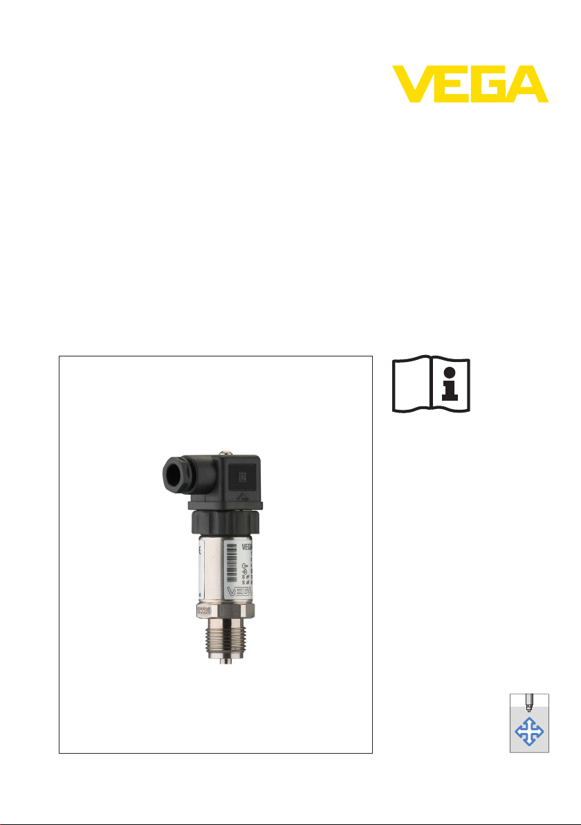
VEGABAR 17
s
Document ID:
27636
Process pressur
e
Page 2

Contents
Contents
1 About this
1.1 Function. . . . . . . . . . . . . . . . . . . . . . . . . . . . . . . . . .
1.2 Target group . . . . . . . . . . . . . . . . . . . . . . . . . . . . . .
1.3 Symbolism used . . . . . . . . . . . . . . . . . . . . . . . . . . . .
2 For your safety
2.1 Authorised personnel . . . . . . . . . . . . . . . . . . . . . . . .
2.2 Appropriate use . . . . . . . . . . . . . . . . . . . . . . . . . . . .
2.3 Warning about incorrect use . . . . . . . . . . . . . . . . . . .
2.4 General safety instructions . . . . . . . . . . . . . . . . . . . .
2.5 Safety label on the instrument . . . . . . . . . . . . . . . . . .
2.6 CE conformity . . . . . . . . . . . . . . . . . . . . . . . . . . . . .
2.7 Measuring range - permissible process pressure . . . .
2.8 Safety instructions for Ex areas . . . . . . . . . . . . . . . . .
2.9 Environmental instructions. . . . . . . . . . . . . . . . . . . . .
3 Product description
3.1 Structure . . . . . . . . . . . . . . . . . . . . . . . . . . . . . . . . .
3.2 Principle of operation . . . . . . . . . . . . . . . . . . . . . . . .
3.3 Operation. . . . . . . . . . . . . . . . . . . . . . . . . . . . . . . . .
3.4 Packaging, transport and storage . . . . . . . . . . . . . . .
4 Mounting
4.1 General instructions . . . . . . . . . . . . . . . . . . . . . . . . .
4.2 Instructions for installation . . . . . . . . . . . . . . . . . . . . .
4.3 Mounting steps. . . . . . . . . . . . . . . . . . . . . . . . . . . . .
5 Connecting to power supply
5.1 Preparing the connection . . . . . . . . . . . . . . . . . . . . .
5.2 Connection procedure. . . . . . . . . . . . . . . . . . . . . . . .
5.3 Wiring plan. . . . . . . . . . . . . . . . . . . . . . . . . . . . . . . .
document
4
4
4
5
5
5
5
6
6
6
6
6
7
8
8
8
10
10
10
12
13
16
6 Setup
6.1 Setup steps . . . . . . . . . . . . . . . . . . . . . . . . . . . . . . .
6.2 Recalibration . . . . . . . . . . . . . . . . . . . . . . . . . . . . . .
7 Maintenance and fault rectification
7.1 Maintenance . . . . . . . . . . . . . . . . . . . . . . . . . . . . . .
7.2 Remove interferences . . . . . . . . . . . . . . . . . . . . . . . .
7.3 Instrument repair . . . . . . . . . . . . . . . . . . . . . . . . . . .
8 Dismounting
8.1 Dismounting steps . . . . . . . . . . . . . . . . . . . . . . . . . .
8.2 Disposal . . . . . . . . . . . . . . . . . . . . . . . . . . . . . . . . .
9 Supplement
9.1 Technical data . . . . . . . . . . . . . . . . . . . . . . . . . . . . .
9.2 Dimensions . . . . . . . . . . . . . . . . . . . . . . . . . . . . . . .
2 VEGABAR 17
18
18
21
21
22
23
23
24
30
27636-EN-120531
Page 3

Contents
Supplementary documentation
Information:
Suppleme
with the delivery. You can find them listed in chapter "Product
description".
Editing status: 2012-05-29
ntary documents appropriate to the ordered version come
27636-EN-120531
VEGABAR 17 3
Page 4
1 About this document
1 About this document
1.1 Function
is operating instructions manual provides all the information you
Th
need for mounting, connection and setup as well as important
instructions for maintenance and fault rectification. Please read this
information before putting the instrument into operation and keep this
manual accessible in the immediate vicinity of the device.
1.2 Target group
This operating instructions manual is directed to trained qualified
personnel. The contents of this manual should be made available to
these personnel and put into practice by them.
1.3 Symbolism used
Information, tip, note
This
symbol indicates helpful additional information.
Caution: If this
result.
Warning: If this warning is ignored, injury to persons and/or serious
damage to the instrument can result.
Danger: If this warning is ignored, serious injury to persons and/or
destruction of the instrument can result.
applications
Ex
Th
symbol indicates special instructions for Ex applications.
is
l List
The dot set in front indicates a list with no implied sequence.
warning is ignored, faults or malfunctions can
à Action
This a
rrow indicates a single action.
1 Sequence
Numbers set in front indicate successive steps in a procedure.
Battery disposal
symbol indicates special information about the disposal of
This
batteries and accumulators.
27636-EN-120531
4 VEGABAR 17
Page 5

2 For your safety
2 For your safety
2.1 Auth
All operations described in this operating instructions manual must be
carried out only by trained specialist personnel authorised by the plant
operator.
During work on and with the device the required personal protective
equipment must always be worn.
orised personnel
2.2 Appropriate use
VEGABAR 17 is a pressure transmitter for measurement of gauge
pressure, absolute pressure and vacuum.
You can find detailed information on the application range in chapter
"Product description".
Operational reliability is ensured only if the instrument is properly used
according to the specifications in the operating instructions manual as
well as possible supplementary instructions.
For safety and warranty reasons, any invasive work on the device
beyond that described in the operating instructions manual may be
carried out only by personnel authorised by the manufacturer. Arbitrary
conversions or modifications are explicitly forbidden.
2.3 Warning about incorrect use
Inappropriate or incorrect use of the instrument can give rise to
application-specific hazards, e.g. vessel overfill or damage to system
components through incorrect mounting or adjustment.
2.4 General safety instructions
This is a high-tech instrument requiring the strict observance of
standard regulations and guidelines. The user must take note of the
safety instructions in this operating instructions manual, the countryspecific installation standards as well as all prevailing safety
regulations and accident prevention rules.
The instrument must only be operated in a technically flawless and
reliable condition. The operator is responsible for trouble-free
operation of the instrument.
During the entire duration of use, the user is obliged to determine the
compliance of the necessary occupational safety measures with the
current valid rules and regulations and also take note of new
regulations.
27636-EN-120531
VEGABAR 17 5
Page 6

2 For your safety
2.5 Safety label
The safety approval markings and safety tips on the device must be
observed.
on the instrument
2.6 CE conformity
The device fulfills the legal requirements of the applicable EC
guidelines. By affixing the CE marking, we confirm successful testing
of the product.
You can find the conformity ce rtificate in the download section of our
homepage.
2.7 Measuring range - permissible process pres-
sure
Due to the application, a measuring cell with a measuring range higher
than the permissible pressure range of the process fitting may have
been integrated. The permissible process pressure is stated with
"Process pressure" on the type label, see chapter 3.1 "Configuration".
For safety reasons, this range must not be exceeded.
2.8 Safety instructions for Ex areas
Please note the Ex-specific safety information for installation and
operation in Ex areas. These safety instructions are part of the
operating instructions manual and come with the Ex-approved
instruments.
2.9 Environmental instructions
Protection of the environment is one of our most important duties. That
is why we have introduced an environment management system with
the goal of continuously improving company environmental protection.
The environment management system is certified according to DIN
EN ISO 14001.
Please help us fulfil this obligation by observing the environmental
instructions in this manual:
l Chapter "Packaging, transport and storage"
l Chapter "Disposal"
6 VEGABAR 17
27636-EN-120531
Page 7
3 Product description
4
3
2
1
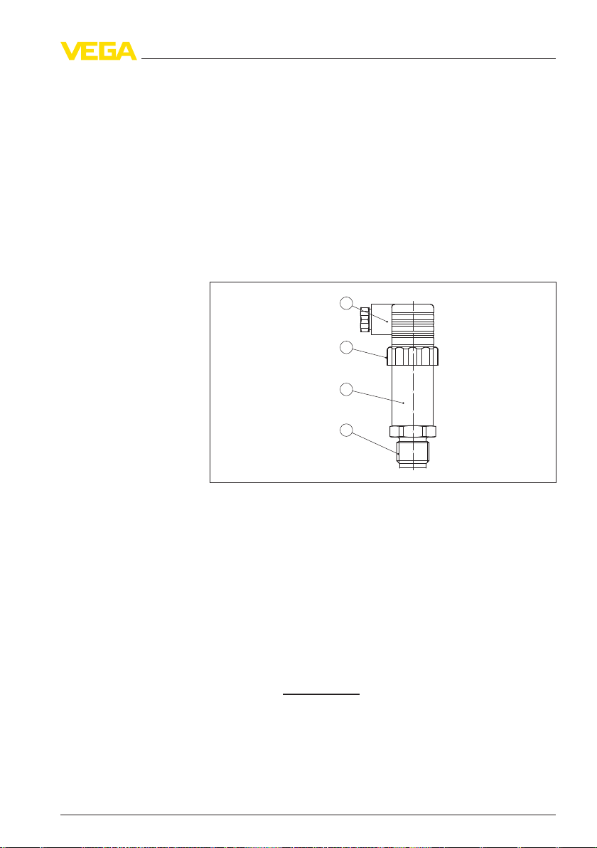
3.1 Structure
3 Product description
pe of delivery
Sco
Structure
e scope of delivery encompasses:
Th
l VEGABAR 17 process pressure transmitter
l Depending on the version, with plug connector, connection cable
or terminal housing
l Documentation
- this operating instructions manual
- Ex-specific "Safety instructions" (with Ex versions)
- if necessary, further certificates
Fig. 1: VEGABAR 17 with
1 Process fitting
2 Housing with electronics
3 Pressure compensation (beneath the knurled nut)
4 Plug connector
plug
connector
according to ISO 4400
Type label
The type label contains the most important data for identification and
use of the instrument:
l Article number
l Serial number
l Technical data
l Article numbers, documentation
With the serial number, you can access the delivery data of the
instrument via
www.vega.com, "VEGA T
ools" and "serial number
search". In addition to the type label outside, you can also find the
serial number on the inside of the instrument.
27636-EN-120531
VEGABAR 17 7
Page 8

3 Product description
cation area
Appli
Functional principle
Voltage supply
Packaging
3.2 Principle of
operation
VEGABAR 17 is a pressure transmitter for measurement of gauge
pressure, absolute pressure or vacuum. Measured products are
gases, vapours and liquids. The front flush versions are also suitable
for use in viscous or contaminated products.
The process pressure acts on the sensor element via the stainless
steel diaphragm. The process pressure causes a resistance change
which is converted into a corresponding output signal and outputted as
measured value.
1)
4 … 20 mA two-wire electronics for voltage supply and measured
value transmission on the same cable.
3.3 Operation
The VEGABAR 17 has no adjustment options.
However, there are two built-in potentiometers for recalibration of zero
and span.
3.4 Packaging, transport and storage
Your instrument was protected by packaging during transport. Its
capacity to handle normal loads during transport is assured by a test
according to DIN EN 24180.
The packaging of standard instruments consists of environmentfriendly, recyclable cardboard. For special versions, PE foam or PE foil
is also used. Dispose of the packaging material via specialised
recycling companies.
Transport
Transport must be carried out under consideration of the notes on the
transport packaging. Nonobservance of these instructions can cause
damage to the device.
Transport inspection
The delivery must be checked for completeness and possible transit
damage immediately at receipt. Ascertained transit damage or
concealed defects must be appropriately dealt with.
Storage
Up to the time of installation, the packages must be left closed and
stored according to the orientation and storage markings on the
outside.
Unless otherwise indicated, the packages must be stored only under
the following conditions:
l Not in the open
1)
Measuring
transmission liquid. Measuring ranges up to 25 bar: strain gauge (DMS)
sensor element on the rear of the stainless steel diaphragm (dry).
ranges up to 16 bar: piezoresistive sensor element with internal
8 VEGABAR 17
27636-EN-120531
Page 9

3 Product description
Stora
ge and transport
temperature
l Dry and dust free
l Not expose
l Protected against solar radiation
l Avoiding mechanical shock and vibration
l Storage and transport temperature see chapter "Supplement -
d to corrosive media
Technical data - Ambient conditions"
l Relative humidity 20 … 85 %
27636-EN-120531
VEGABAR 17 9
Page 10
4 Mounting
4 Mounting
bility for the pro-
Suita
cess condition
Diaphragm protection
Checking the diaphragm
Mounting position
s
4.1 General ins
Make sure that all parts of the instrument exposed to the process, in
particular the sensor element, process seal and process fitting, are
suitable for the existing process conditions. These include above all
the process pressure, process temperature as well as the chemical
properties of the medium.
You can find the specifications in chapter "Technical data" and on the
type label.
To protect the diaphragm, the process fitting is covered by a protective
cap.
Remove the protective cap just before installation so that the
diaphragm will not get damaged. It is recommended to keep the cap
and use it again later for storage or transport.
tructions
4.2 Instructions for installation
Please check the diaphragm visually for damage and leaking fluid
before mounting and setting up the instrument. Make sure that the
diaphragm doesn't get damaged during installation.
Caution:
The instr
condition and has an undamaged diaphragm.
VEGABAR 17 functions in any installation position. It is mounted
according to the same directives as a manometer (DIN EN 839-2).
ument may only be used if it is in a technically flawless
Information:
We recommen
siphons from our line of accessories.
d using lock fittings, measuring instrument holders and
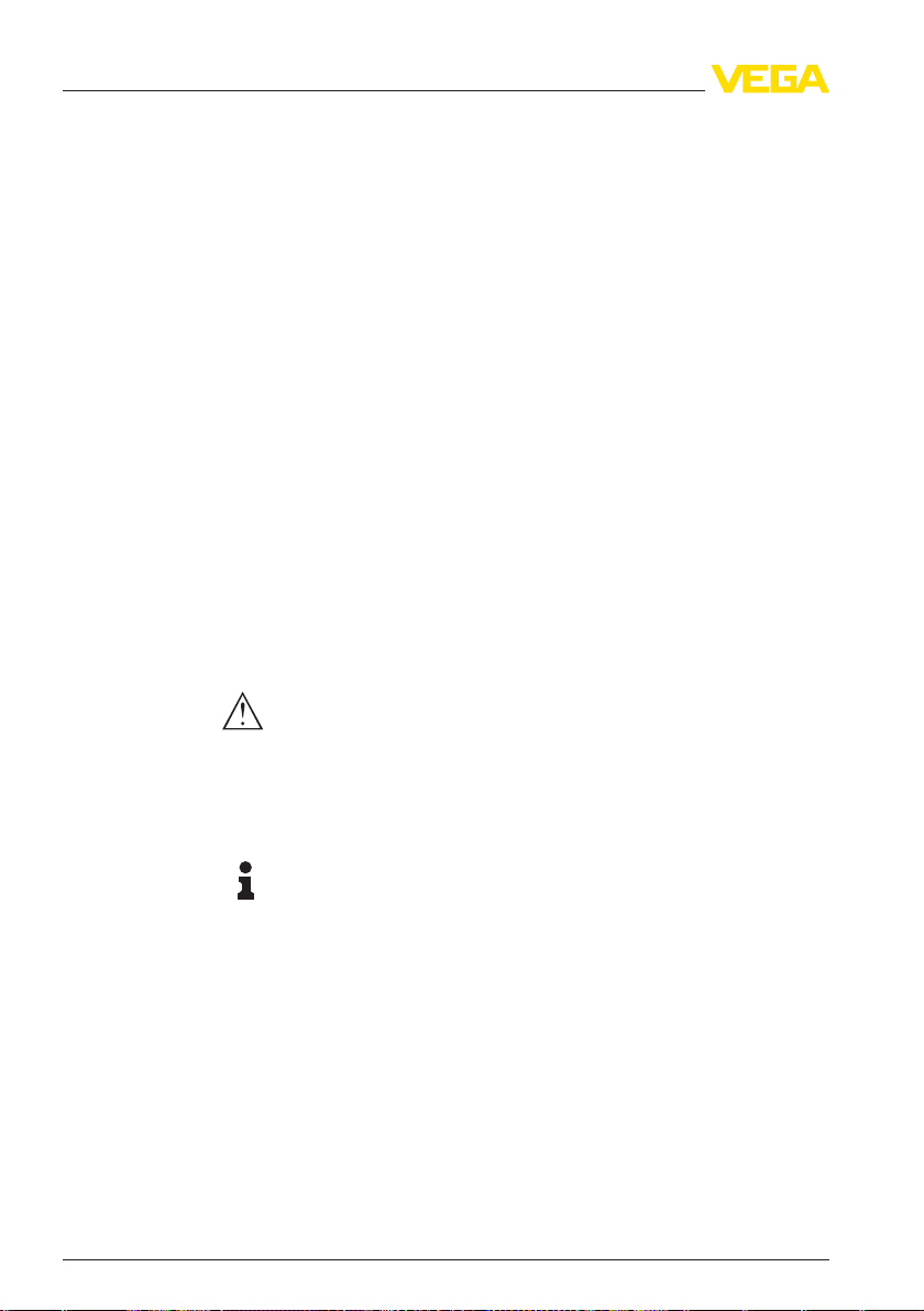
4.3 Mounting steps
Welding the socket
Sealing/Screwing in
10 VEGABAR 17
For mounting VEGABAR 17, a welded socket is required. You can find
these components in the supplementary instructions manual "Welded
socket and seals".
Use the seal fitting to the instrument, or in case of NPT connections, a
high-resistance sealing material.
Screw VEGABAR 17 into the welded socket with a wrench applied to
the hexagon of the process fitting. For the proper torque see chapter
"Technical data", for spanner size see chapter "Dimensions".
27636-EN-120531
Page 11

Fig. 2: Mounting of VEGABAR 17
4 Mounting
27636-EN-120531
VEGABAR 17 11
Page 12

5 Connecting to power supply
5 Connecting to power supply
Note safety instructions
Take note of sa-
fety instructions
for Ex applications
Select power supply
Select connection cable
5.1 Preparin
Always keep in mind the following safety instructions:
l Connect only in the complete absence of line voltage
l If overvoltage surges are expected, overvoltage arresters should
be installed
Tip:
We recomm
In hazardous areas you must take note of the respective regulations,
conformit
supply units.
The supply voltage and the current signal are carried on the same twowire connection cable.
Provide a reliable separation between the supply circuit and the mains
circuits according to DIN VDE 0106 part 101.
VEGA power supply units VEGATRENN 149AEx, VEGASTAB 690,
VEGADIS 371 as well as all VEGAMETs meet this requirement. When
using one of these instruments, protection class III is ensured for
VEGABAR 17.
Keep in mind the following additional factors that influence the
operating voltage:
l Output voltage of the power supply unit can be lower under
l Influence of additional instruments in the circuit (see load values in
The instrument is connected with standard two-wire cable without
screen. If electromagnetic interference is expected which is above the
test values of EN 61326 for industrial areas, screened cable should be
used.
Use cable with round cross-section. A cable outer diameter of 5 … 9 mm
(0.2 … 0.35 in) ensures the seal effect of the cable gland. If you are
using cable with a different diameter or cross-section, exchange the
seal or use a suitable cable gland.
For the version with round plug connector M12 x 1, a suitable, ready-
made connection cable (article no. ASL.1S.) in 5 m, 10 m or 25 m
lengths is available from the line of VEGA accessories.
y and type approval certificates of the sensors and power
nominal load (with a sensor current of 20.5 mA or 22 mA in case of
fault message)
chapter "Technical data")
g the connection
end VEGA overvoltage arrester ÜSB 62-36G.X.
27636-EN-120531
12 VEGABAR 17
Page 13

5 Connecting to power supply
screening and
Cable
grounding
Selec
t conne
tion cable
applications
c-
for Ex
Connect the cable screen on both ends to ground potential.
If potenti
processing side must be made via a ceramic capacitor (e. g. 1 nF,
1500 V). The low frequency potential equalisation currents are thus
suppressed, but the protective effect against high frequency interference signals remains.
Warning:
Considerab
as vessels with cathodic corrosion protection. Very large equalisation
currents can flow through the cable screen when the screen is
grounded on both ends. To avoid this, the cable screen must be
connected to ground potential only on one end (inside the switching
cabinet) in such applications. The cable screen must not be
connected to the internal ground terminal in the sensor and the outer
ground terminal on the housing not to potential equalisation!
Information:
The
tube, etc.) are conductively connected with the inner and outer ground
terminal on the housing. This connection exists either as a direct
metallic contact or via the shielding of the special connection cable on
instruments with external electronics. You can find specifications on
the potential connections within the instrument in chapter "Technical
data".
Ta
appl
al equalisation currents are expected, the connection on the
le potential differences exist inside galvanic plants as well
metallic parts of the instrument (antenna, transmitter, concentric
ke note of the corresponding installation regulations for E
ications.
x
5.2 Connection procedure
Connection via angle
plug connec
27636-EN-120531
VEGABAR 17 13
tor
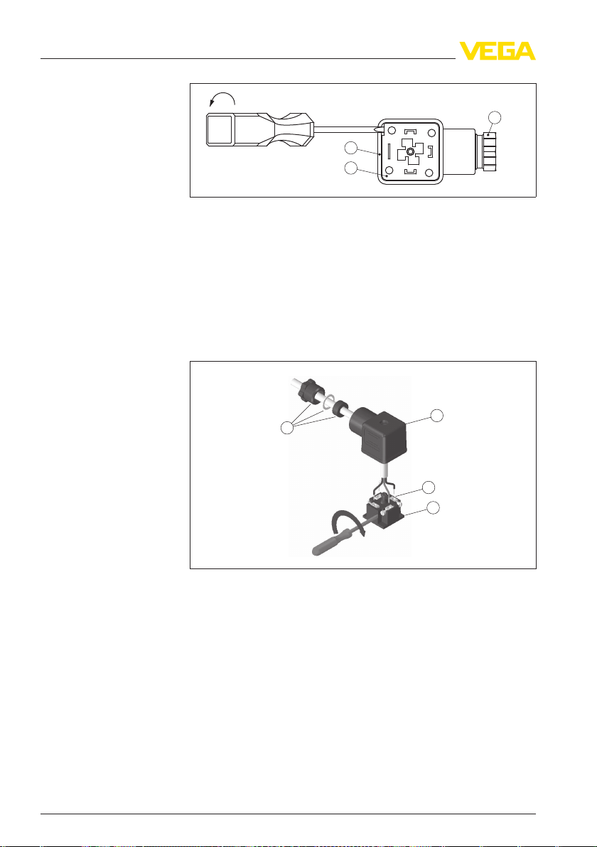
Proceed as follows:
1 Loosen the screw on the rear of the plug connector
2 Remove the plug connector and seal from VEGABAR 17
3 Remove the plug insert from the plug housing
Page 14
1
2
3
2
3
1
4
5 Connecting to power supply
Fig. 3: Loosen the plug
1 Cable gland
2 Plug insert
3 Plug housing
insert
4 Remove approx. 5 cm of the cable mantle, strip approx. 1 cm
insulation from the individual wires
5 Lead the cable through the cable gland into the plug housing
6 Connect the wire ends to the screw terminals according to the
wiring plan
Fig. 4: Connection to the
1 Cable gland
2 Plug housing
3 Plug insert
4 Plug seal
screw terminals
7 Snap the plug insert into the plug housing and insert the sensor
seal
8 Plug the plug insert with seal to VEGABAR 17 and tighten the
screw
The electrical connection is finished.
Connection via angle
plug connector with hinged cover
Proceed as follows:
14 VEGABAR 17
27636-EN-120531
Page 15

4
32
1
3
2
1
1
5
2
3
4
5 Connecting to power supply
1 Loosen the screw in the cover of the plug connector
2 Open the
cover and remove it
3 Press the plug insert downwards
4 Loosen the screws of the strain relief and cable entry
Fig. 5: Loosen the plug
1 Plug insert
2 Strain relief
3 Cable gland
4 Plug housing
insert
5 Remove approx. 5 cm of the cable mantle, strip approx. 1 cm
insulation from the individual wires
6 Lead the cable through the cable gland into the plug housing
7 Connect the wire ends to the screw terminals according to the
wiring plan
Fig. 6: Connection to the
1 Cable gland
2 Cover
3 Plug housing
4 Plug insert
5 Plug seal
screw terminals
27636-EN-120531
VEGABAR 17 15
Page 16

1
2
3
+
-
1
3
+
-
1
324
1
5 Connecting to power supply
d plug connector
Angle
according to ISO 440
0
8 Snap the plug insert into the plug housing and insert the sensor
seal
Information:
Note the correct arrangement, see illustration
9 Tighten the screws on the strain relief and cable entry
10 Hook in the cover and push onto the plug connection, tighten
cover screw
11 Plug the plug insert with seal to VEGABAR 17 and tighten the
screw
The electrical connection is finished.
5.3 Wiring plan
Fig. 7: Wiring
VEGABAR 17
1 Voltage supply and signal output
Round plug connector
M12 x 1
Fig. 8: Wiring plan, round plug
1 Voltage supply and signal output
Connection via connection cable with 4-pole socket M12 x 1
(accessory)
16 VEGABAR 17
plan, angle
connector according to ISO 4400, top view to
plug
connector M12 x 1, top view to VEGABAR 17
27636-EN-120531
Page 17

1
2
3
321
–
+
–
+
4 5
1
2
Cable
5 Connecting to power supply
Wire colour Socket
Brown 1
White 2
Blue 3
Black 4
outlet
Terminal housing
Fig. 9: Wiring plan cable
1 brown (+) power supply and signal output
2 green (-) power supply and signal output
3 blue = cable screen
Fig. 10: Wiring plan, terminal housing
power supply or the processing system
1 To
2 Control instrument (4 … 20 mA measurement)
outlet
27636-EN-120531
VEGABAR 17 17
Page 18

6 Setup
6 Setup
6.1 Setup steps
mounting and electrical connection, VEGABAR 17 is ready for
After
operation.
VEGABAR 17 delivers a current of 4 … 20 mA corresponding to the
actual process pressure.
Further settings are not necessary.
6.2 Recalibration
With both instruments with thread ring or field housing, zero and span
can be adjusted via integrated potentiometers. Adjustment range:
l Zero ± 5 %
l Span ± 5 %
This allows, for example, the consideration of an installation position
different from the reference installation position.
A shifting of zero shifts span also respectively.
Note:
The potenti
calibration equipment (at least 3 times more precise than the deviation
of VEGABAR 17).
Recommended recalibration cycle: 1 year.
ometer for span should only be used if you have adequate
Instrum
ents with plug
connector or
let
18 VEGABAR 17
cable out-
Proceed as follows:
1 Loosen the plug connector and screw the screwed ring in
connected status
2 Place the plug connector onto the instrument place and pull both
carefully out of the instrument
27636-EN-120531
Page 19

1
2
3
4
5
6
2
1
6 Setup
Fig. 11: Open the instrument
1 Plug
2 Plug seal
3 Screwed ring
4 Instrument plug
5 Plug seal
6 Housing
connector
3 Set zero in unpressurized status, check 4 mA signal in the circuit
4 Set span with exact reference pressure
5 Check zero
Fig. 12: Adjustment of zero
1 zero (Z)
2 span (S)
and span
6 Assemble the instrument and connect it.
27636-EN-120531
VEGABAR 17 19
Page 20

4
5
6 Setup
Instruments with terminal housin
g
Proceed as follows:
1 Screw on
Fig. 13: Adjustment of zero
1 zero (Z)
2 span (S)
the housing cover in connected status
and span
2 Set zero in unpressurized status, check 4 mA signal in the circuit
3 Set a span with a sufficiently precise reference pressure
4 Check zero
5 Screw the housing cover back on
20 VEGABAR 17
27636-EN-120531
Page 21

7 Maintenance and fault rectificati
7 Maintenance and fault rectification
on
Reaction when malfunctions occur
reasons
Failure
Fault rectification
24 hour ser
Check the 4 … 20 mA
signal
vice hotline
7.1 Maintena
If the instrument is used properly, no special maintenance is required
in normal operation.
nce
7.2 Remove interferences
The operator of the system is responsible for taking suitable measures
to rectify faults.
VEGABAR 17 offers maximum reliability. Nevertheless, faults can
occur during operation. These may be caused by the following, e.g.:
l Sensor
l Process
l Voltage supply
l Signal processing
The first measure to be taken is to check the output signal. In many
cases, the causes can be determined this way and the faults rectified.
Should these measures not be successful, please call in urgent cases
the VEGA service hotline under the phone no. +49 1805 858550.
The hotline is available to you 7 days a week round-the-clock. Since
we offer this service world-wide, the support is only available in the
English language. The service is free of charge, only the standard
telephone costs will be charged.
? No 4 … 20 mA signal
l Connection to voltage supply wrong
à Check connection according to chapter "Connection steps"
and if necessary, correct according to chapter "Wiring plan"
l No voltage supply
à Check cables for breaks; repair if necessary
l Operating voltage too low or load resistance too high
à Check, adapt if necessary
? Steady output signal with pressure change
l electronics module or measuring cell defective
à Exchange the instrument or send it in for repair
In Ex applications, the regu
circuits must be observed.
27636-EN-120531
VEGABAR 17 21
lations for the wiring of intrinsically safe
Page 22

7 Maintenance and fault rectificati
on
Reaction after fault rectification
Depending on the reason for the fault and the measures taken, the
described in chapter "Set up" may have to be carried out again.
steps
7.3 Instrument repair
If a repair is necessary, please proceed as follows:
You can download a return form (23 KB) from our Internet homepage
www.vega.com under: "Dow
form".
By doing this you help us carry out the repair quickly and without
having to call back for needed information.
l Print and fill out one form per instrument
l Clean the instrument and pack it damage-proof
l Attach the completed form and, if need be, also a safety data
sheet outside on the packaging
l Please ask the agency serving you for the address of your return
shipment. You can find the respective contact data on our website
www.vega.com under: "Compa
nloads - Forms and certificates - Repair
ny - VEGA worldwide"
22 VEGABAR 17
27636-EN-120531
Page 23

8 Dismounting
8 Dismounting
8.1 Dism
Warning:
Before dismounting, be aware of dangerous process conditions such
as e.g. pressure in the vessel, high temperatures, corrosive or toxic
products etc.
Take note of chapters "Mounting" and "Connecting to power supply"
and carry out the listed steps in reverse order.
ounting steps
8.2 Disposal
The instrument consists of materials which can be recycled by
specialised recycling companies. We use recyclable materials and
have designed the electronics to be easily separable.
WEEE directive 2002/96/EG
This instrument is not subject to the WEEE directive 2002/96/EG and
the respective national laws. Pass the instrument directly on to a
specialised recycling company and do not use the municipal collecting
points. These may be used only for privately used products according
to the WEEE directive.
Correct disposal avoids negative effects on humans and the environment and ensures recycling of useful raw materials.
Materials: see chapter "Technical data"
If you have no way to dispose of the old instrument properly, please
contact us concerning return and disposal.
27636-EN-120531
VEGABAR 17 23
Page 24

9 Supplement
9 Supplement
9.1 Technical
data
General data
Parameter, pressure Gauge pressure, absolute pressure, vacuum
Measuring principle Piezoresistive/Thin film DMS
Communication interface None
Materials and weights
Materials, wetted parts
- Process fitting 316Ti
- Diaphragm 316Ti
- Diaphragm with front flush version 316Ti, Hastelloy C4
- Seal, O-ring FPM, FKM, EPDM, NBR
Materials, non-wetted parts
- Internal transmission liquid Synthetic oil, Halocarbon oil
2)3)
- Housing 316Ti
- Terminal housing 316Ti
- Ground terminal 316Ti
- Plug PA
- Cable gland PA, 316Ti
- Plug seal Silicone
- Connection cable PUR
Available cable length max. 40 m
Weight approx.
- Version with plug connector, cable outlet 0.2 kg (0.441 lbs)
- Version with terminal housing 0.35 kg (0.772 lbs)
Torque max. 50 Nm (36.88 lbft)
Output variable
Output signal 4 … 20 mA
Zero and span adjustable via potentiometer ±5 %
Dead time ≤ 1 ms
Step response time (10 … 90 %)
- Standard version ≤ 1 ms
2)
Synthetic
processing industry. For measuring ranges up to 25 bar not available.
3)
Halocarbon
ranges, not with absolute measuring ranges < 1 bar
oil: For measuring ranges
oil: With version oil
and greasefree, not with vacuum measuring
up to 16 bar, FDA listed for the food
.
abs
24 VEGABAR 17
27636-EN-120531
Page 25

9 Supplement
- Version for medium temperature < -30 °C
≤ 10 ms
(-22 °F)
- Vers
ion for measuring ranges > 25 bar ≤ 10 ms
- Version with front-flush diaphragm ≤ 10 ms
Reference conditions and actuating variables (according to DIN EN 60770-1)
Reference conditions according to DIN EN 61298-1
- Temperature +15 … +25 °C (+59 … +77 °F)
- Relative humidity 45 … 75 %
- Air pressure 860 … 1060 mbar/86 … 106 kPa (12.5 … 15.4 psi)
Determination of characteristics Limit point adjustment according to IEC 61298-2
Reference installation position upright, diaphragm points downward
Influence of the installation position depending on the chemical seal version
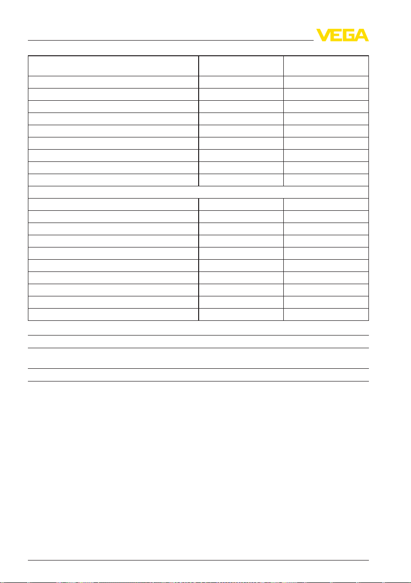
Input variable
The availability of the respective measuring range depends on the corresponding process fitting.
The specifications on overload capacity are only an overview and refer to the measuring cell.
Limitations due to the material and form of the process fitting are possible. The specifications on
the type label always apply.
Nominal range Overload capacity, max.
pressure
Gauge pressure
-0.1 … 0 bar/-10 … 0 kPa 1 bar/100 kPa -1 bar/-100 kPa
-0.16 … 0 bar/-16 … 0 kPa 1.5 bar/150 kPa -1 bar/-100 kPa
-0.25 … 0 bar/-25 … 0 kPa 2 bar/200 kPa -1 bar/-100 kPa
-0.4 … 0 bar/-40 … 0 kPa 2 bar/200 kPa -1 bar/-100 kPa
-0.6 … 0 bar/-60 … 0 kPa 4 bar/400 kPa -1 bar/-100 kPa
-1 … 0 bar/-100 … 0 kPa 5 bar/500 kPa -1 bar/-100 kPa
-1 … 3 bar/-100 … 300 kPa 10 bar/1000 kPa -1 bar/-100 kPa
0 … 0.1 bar/0 … 10 kPa 1 bar/100 kPa -1 bar/-100 kPa
0 … 0.16 bar/0 … 16 kPa 1.5 bar/150 kPa -1 bar/-100 kPa
0 … 0.25 bar/0 … 25 kPa 2 bar/200 kPa -1 bar/-100 kPa
0 … 0.4 bar/0 … 40 kPa 2 bar/200 kPa -1 bar/-100 kPa
0 … 0.6 bar/0 … 60 kPa 4 bar/400 kPa -1 bar/-100 kPa
0 … 1 bar/0 … 100 kPa 5 bar/500 kPa -1 bar/-100 kPa
0 … 1.6 bar/0 … 160 kPa 10 bar/1000 kPa -1 bar/-100 kPa
0 … 2.5 bar/0 … 250 kPa 10 bar/1000 kPa -1 bar/-100 kPa
0 … 4 bar/0 … 40 kPa 17 bar/1700 kPa -1 bar/-100 kPa
0 … 6 bar/0 … 600 kPa 35 bar/3500 kPa -1 bar/-100 kPa
0 … 10 bar/0 … 1000 kPa 35 bar/3500 kPa -1 bar/-100 kPa
0 … 16 bar/0 … 1600 kPa 80 bar/8000 kPa -1 bar/-100 kPa
Overload capacity, min.
pressure
27636-EN-120531
VEGABAR 17 25
Page 26
9 Supplement
Nominal range Overload capacity, max.
0 … 25 bar/0 … 2500 kPa 50 bar/5000 kPa -1 bar/-100 kPa
0 … 40 bar/0 … 4000 kPa 80 bar/8000 kPa -1 bar/-100 kPa
0 … 60 bar/0 … 6000 kPa 120 bar/12 MPa -1 bar/-100 kPa
0 … 100 bar/0 … 10 MPa 200 bar/20 MPa -1 bar/-100 kPa
0 … 160 bar/0 … 16 MPa 320 bar/32 MPa -1 bar/-100 kPa
0 … 250 bar/0 … 25 MPa 500 bar/50 MPa -1 bar/-100 kPa
0 … 400 bar/0 … 40 MPa 800 bar/80 MPa -1 bar/-100 kPa
0 … 600 bar/0 … 60 MPa 1200 bar/120 MPa -1 bar/-100 kPa
0 … 1000 bar/0 … 100 MPa 1500 bar/150 MPa -1 bar/-100 kPa
Absolute pressure
0 … 0.25 bar/0 … 25 kPa 2 bar/200 kPa
0 … 0.4 bar/0 … 40 kPa 2 bar/200 kPa
0 … 0.6 bar/0 … 60 kPa 4 bar/400 kPa
0 … 1 bar/0 … 100 kPa 5 bar/500 kPa
0 … 1.6 bar/0 … 160 kPa 10 bar/1000 kPa
0 … 2.5 bar/0 … 250 kPa 10 bar/1000 kPa
0 … 4 bar/0 … 400 kPa 17 bar/1700 kPa
0 … 6 bar/0 … 600 kPa 35 bar/3500 kPa
0 … 10 bar/0 … 1000 kPa 35 bar/3500 kPa
0 … 16 bar/0 … 1600 kPa 80 bar/8 MPa
Deviation
4)
pressure
Overload
pressure
capacity, min.
Deviation ≤ 0.5 %
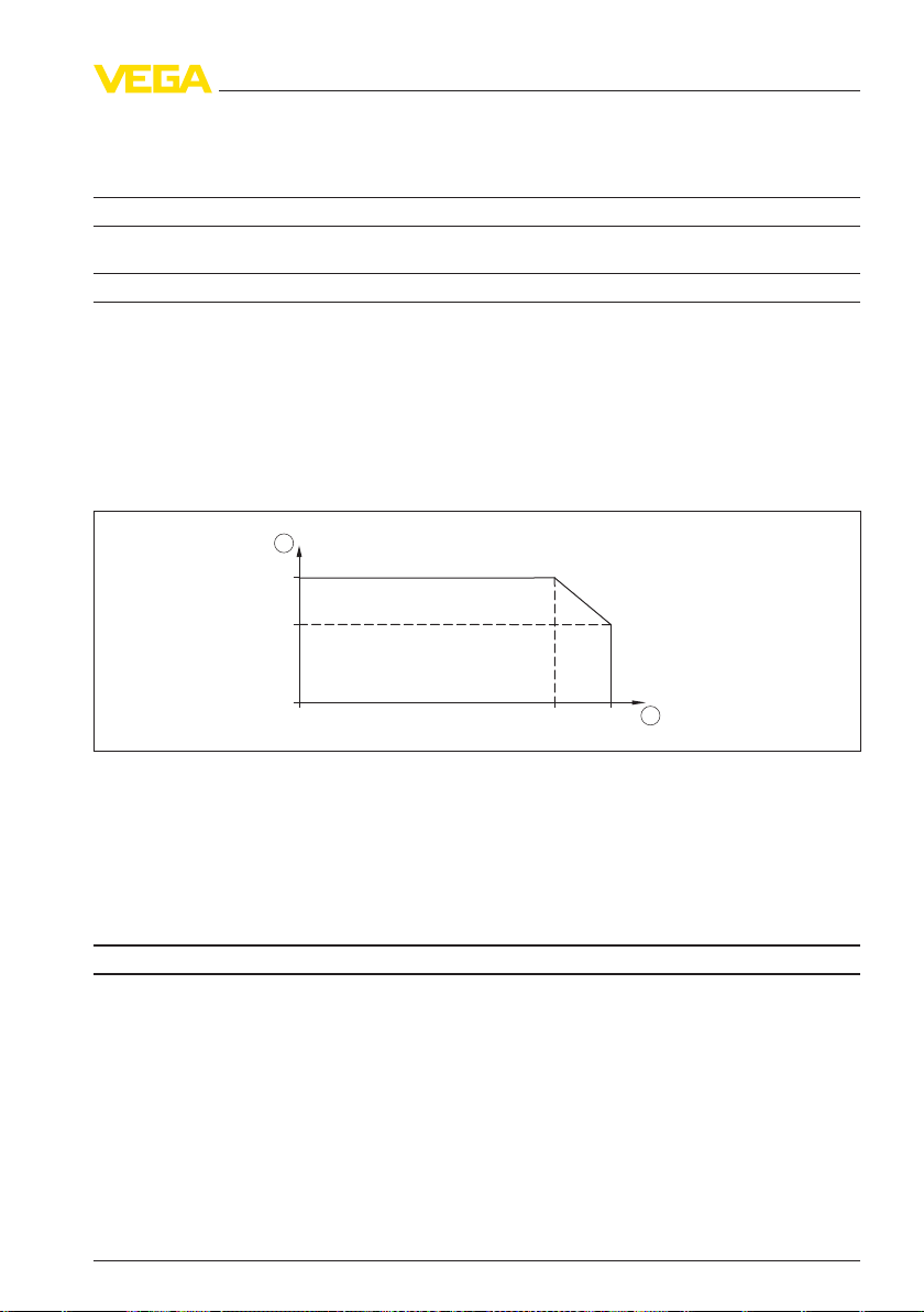
Influence of the product or ambient temperature
5)
The following specifications apply to values within the compensated temperature range, i.e.
0 … 80 °C (176 °F), reference temperature 20 °C (68 °F ).
Average temperature coefficient of the zero signal
- Standard < 0.2 %/10 K
- Meas. ranges 0 … 0.1 and 0 … 0.16 bar < 0.4 %/10 K
Average temperature coefficient of the span < 0.2 %/10 K
The following specifications are valid for values not within the compensated temperature range.
Average temperature coefficient of the zero signal
- Standard typ. < 0.2 %/10 K
- Meas. ranges 0 … 0.1 and 0 … 0.16 bar typ. < 0.4 %/10 K
4)
5)
Relating
ducibility.
Relating
to the adjusted
to the set
span, incl. non-linearity, hysteresis and non-repro-
span, incl. hysteresis and repeatability.
26 VEGABAR 17
27636-EN-120531
Page 27
Average temperature coefficient of the span typ. < 0.2 %/10 K
2
1
55°C
(131°F)
80°C
(176°F)
130°C
(266°F)
150°C
(302°F)
Long-term stability (according to DIN 16086, DINV 19259-1 and IEC 60770-1)
Long-term drift of the zero signal
6)
< 0.2 %/year
Ambient conditions
Ambient temperature (note temperature derating!)
- Cable outlet -20 … +80 °C (-4 … +176 °F)
- Round plug connector M12 x 1 -25 … +80 °C (-13 … +176 °F)
- Angled plug connector according to
-40 … +80 °C (-40 … +176 °F)
ISO 4400
- Terminal housing -50 … +80 °C (-58 … +176 °F)
- with cooling element -20 … +80 °C (-4 … +176 °F)
9 Supplement
Fig. 14: Temperature
1 Ambient
2 Process
derating VEGABAR 17
temperature
temperature
Storage and transport temperature
- Standard -30 … +100 °C (-22 … +212 °F)
- with cooling element -20 … +100 °C (-4 … +212 °F)
Process conditions
Product temperature
- Standard -30 … +100 °C (-22 … +212 °F)
- additional -30 … +125 °C (-22 … +257 °F)
- with cooling element -20 … +150 °C (-4 … +302 °F)
- Measuring ranges from 400 bar -30 … +70 °C (-22 … +158 °F)
Shock resistance
- Version with terminal housing 600 g according to IEC 60068-2-27 (mechanical
shock)
6)
Under
reference
conditions, relating
to
the adjusted span.
27636-EN-120531
VEGABAR 17 27
Page 28

9 Supplement
- Version with plug connector or cable
outlet
according to IEC 60068-2-27 (mechanical
1000 g
shock)
- Version with cooling element 400 g according to IEC 60068-2-27 (mechanical
shock)
Vibration resistance
- Version with terminal housing or cooling
element
- Version with plug connector or cable
outlet
10 g according to IEC 60068-2-6 (resonance
vibration)
20 g according to IEC 60068-2-6 (vibration at
resonance)
Electromechanical data
Angled plug connector
- Version 4-pin according to ISO 4400
- Outer cable diameter 6 … 8 mm
Circular plug connector
- Version 4-pole M12 x 1
Cable outlet
- Diameter 6.8 mm
Terminal housing
- Cable entry for cable outer diameter 6 … 8 mm
- Spring-loaded terminals for wire cross-
2.5 mm² (AWG 14)
section up to
Voltage supply
Operating voltage
- Version with plug or cable outlet 10 … 30 V DC
- Version with terminal housing 11 … 30 V DC
Load
- Version with cable outlet RA ≤ (U-10V)/0,02 A- (length of the cable version in
m x 0.14 Ω)
- Version with plug see diagram
- Version with terminal housing see diagram
Electrical protective measures
Protection rating
7)
- with angled plug connector IP 65
- with round plug connection IP 65
- with cable outlet IP 67, IP 68 (0.5 bar)
- with terminal housing IP 67
Voltage resistance Insulation according to EN 50020, 6.4, 12
7)
According
to EN 60529/IEC 529.
28 VEGABAR 17
27636-EN-120531
Page 29

9 Supplement
Interference resistance
- HF 10 V/m
- Burst 2 kV
protective measures
Other
- Interpolation protection Available
- Overvoltage protection up to 36 V DC
Approvals
Instruments with approvals can have different technical data depending on the version.
That's why the associated approval documents have to be noted with these instruments. They are
part of the delivery or can be downloaded under
number search" as well as via "Downloads" and "Approvals".
www.vega.com via "VE
GA Tools" and "serial
27636-EN-120531
VEGABAR 17 29
Page 30
G1/4
~116 mm (4.57 ")
2 mm
(0.08")
13 mm
(0.51")
2 mm
ø 5 mm
(0.20")
ø 9,5 mm
(0.37")
SW27
G1/2
~123 mm (4.84 ")
ø 27 mm
(1.06")
3 mm
(0.12")
3 mm
20 mm
(0.79")
ø 6 mm
(0.24")
ø 17,5 mm
(0.69")
G1/2
14 mm
(0.55")
10 mm
(0.39")
~119,5 mm (4.70")
G1/2
G¼
~123 mm (4.84 ")
20 mm
(0.79")
3 mm
(0.12")
ø 17,5 mm
(0.69")
G1/2
10 mm
(0.39")
ø 18 mm
(0.71")
20,5 mm
(0.81")
~126 mm (4.96")
G1
20,5 mm
(0.81")
10 mm
(0.39")
~126 mm (4.96")
ø 30 mm
(1.18")
SW41
G1
28 mm
(1.10")
~135 mm (5.31")
ø 30 mm
(1.18")
1/4NPT
1/2NPT
~116 mm (4.57")
13 mm
(0.51")
~123 mm (4.84")
19 mm
(0.75")
GBX
NBX NDX
84L/84B
GDX
TBX
851/85L/85B861/86L/86B
GTX
9 Supplement
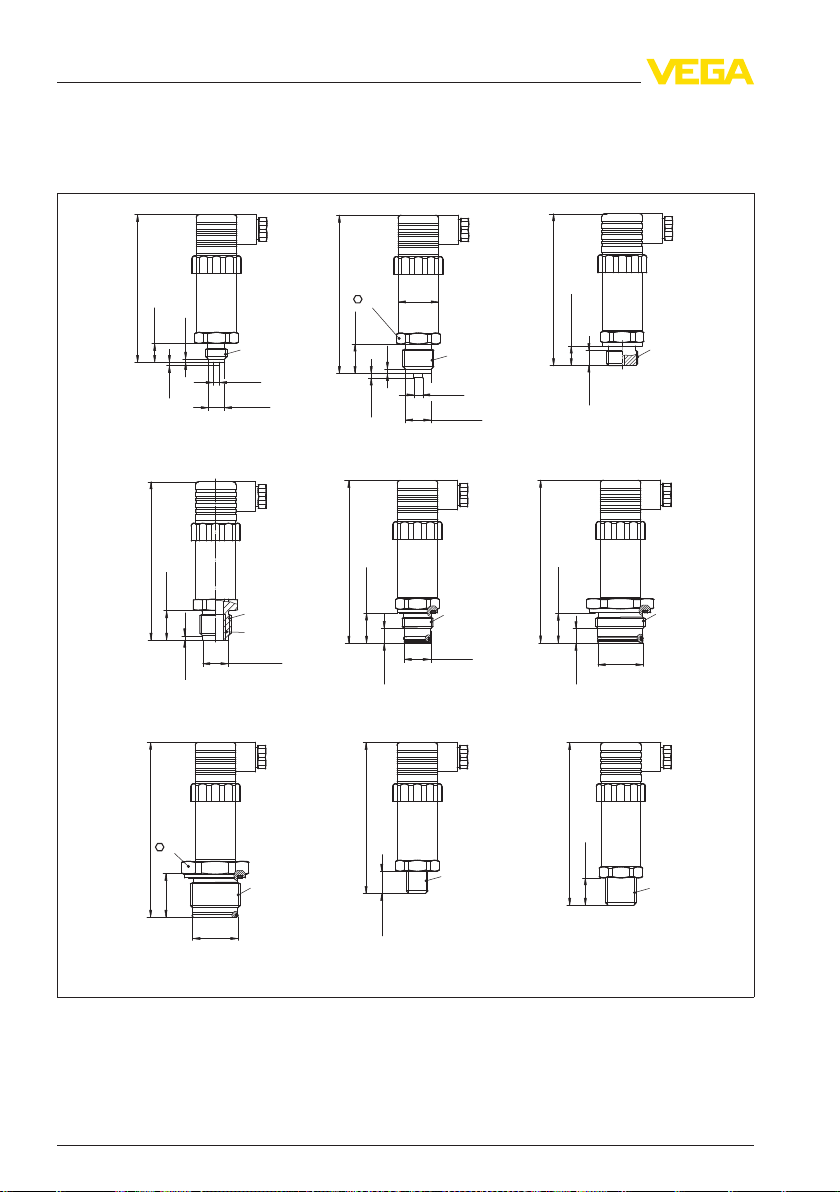
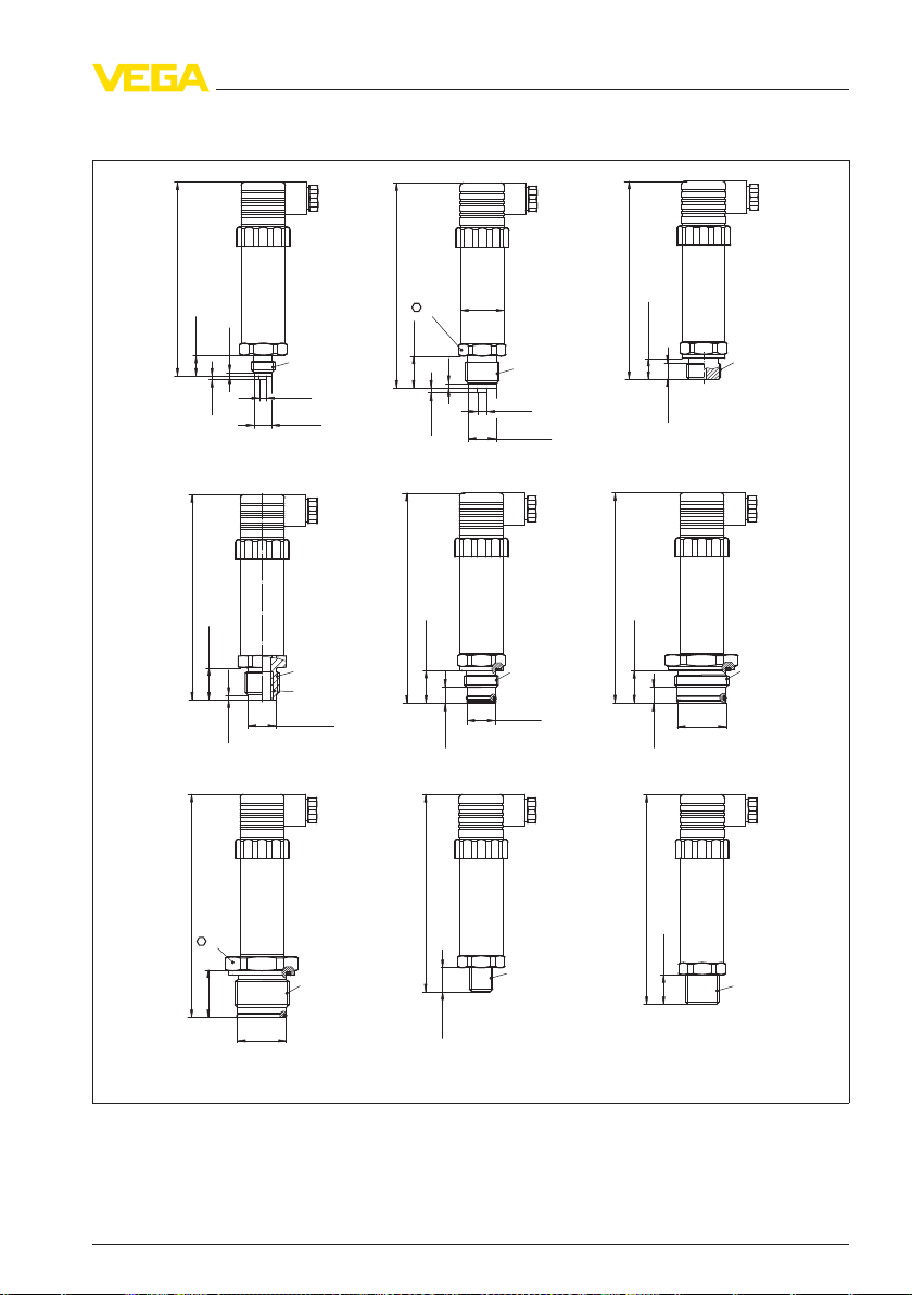
9.2 Dimensions
BAR 17 - standard housing
VEGA
Fig. 15: VEGABAR 17 standard
connection, GTX = G½ A according
25 bar, 851/85L/85B = G1 B front-flush with O-ring up to 1.6 bar, 861/86L/86B = G½ B front-flush with O-ring
> 1.6 bar, NBX = ¼ NPT thread, NDX = ½ NPT thread
30 VEGABAR 17
housing, GBX = G¼ B manometer
to DIN 3852-E, TBX = G½ B, inside G¼ B, 84L/84B = G1 B front-flush max.
connection, GDX = G½ B manometer
27636-EN-120531
Page 31
SW27
G1/4
G1/2
1/4NPT
1/2NPT
G1
10 mm
(0.39")
~136 mm (5.35 ")
~136 mm (5.35")
~143 mm (5.63 ")
ø 27 mm
(1.06")
SW41
G1
28 mm
(1.10")
~155 mm (6.10")
ø 30 mm
(1.18")
13 mm
(0.51")
2 mm
(0.08")
3 mm
(0.12")
3 mm
20 mm
(0.79")
13 mm
(0.51")
2 mm
ø 5 mm
(0.20")
ø 6 mm
(0.24")
ø 9,5 mm
(0.37")
ø 17,5 mm
(0.69")
G1/2
G¼
ø 30 mm
(1.18")
G1/2
10 mm
(0.39")
ø 18 mm
(0.71")
G1/2
14 mm
(0.55")
10 mm
(0.39")
~139,5 mm (5.49")
20,5 mm
(0.81")
20,5 mm
(0.81")
20 mm
(0.79")
3 mm
(0.12")
ø 17,5 mm
(0.69")
~146 mm (5.75")
~143 mm (5.63 ")
~146 mm (5.75")
~143 mm (5.63 ")
19 mm
(0.75")
GBX
NBX NDX
84L/84B
GDX
TBX
851/85L/85B861/86L/86B
GTX
9 Supplement
VEGABAR 17 - Standard ho
using (Ex version)
Fig. 16: VEGABAR 17 standard housing, GBX = G¼ B manometer connection, GDX = G½ B manometer
connection, GTX = G½ A according
25 bar, 851/85L/85B = G1 B front-flush with O-ring up to 1.6 bar, 861/86L/86B = G½ B front-flush with O-ring
> 1.6 bar, NBX = ¼ NPT thread, NDX = ½ NPT thread
27636-EN-120531
VEGABAR 17 31
to DIN 3852-E, TBX = G½ B, inside G¼ B, 84L/84B = G1 B front-flush max.
Page 32

SW27
G1/4
G1/2
1/4NPT
1/2NPT
G1
20,5 mm
(0.81")
10 mm
(0.39")
~128 mm (5.04 ")
~128 mm (5.04")
~135 mm (5.31 ")
ø 27 mm
(1.06")
SW41
G1
28 mm
(1.10")
~147 mm (5.79")
ø 30 mm
(1.18")
13 mm
(0.51")
2 mm
(0.08")
3 mm
(0.12")
3 mm
20 mm
(0.79")
~135 mm (5.31")
13 mm
(0.51")
2 mm
ø 5 mm
(0.20")
ø 6 mm
(0.24")
ø 9,5 mm
(0.37")
ø 17,5 mm
(0.69")
G1/2
G¼
ø 30 mm
(1.18")
G1/2
10 mm
(0.39")
ø 18 mm
(0.71")
G1/2
14 mm
(0.55")
10 mm
(0.39")
~131,5 mm (5.18")
20,5 mm
(0.81")
20 mm
(0.79")
3 mm
(0.12")
ø 17,5 mm
(0.69")
19 mm
(0.75")
ø 61 mm (2.40")
max. 90 mm
(3.54")
~138 mm (5.43")
~138 mm (5.43")
~135 mm (5.31 ")
GBX
NBX NDX
84L/84B
GDX
TBX
851/85L/85B861/86L/86B
GTX
9 Supplement
VEGABAR 17 - terminal housing
Fig. 17: VEGABAR 17 terminal housing, GBX = G¼ B manometer connection, GDX = G½ B manometer
connection, GTX = G½ A according
25 bar, 851/85L/85B = G1 B front-flush with O-ring up to 1.6 bar, 861/86L/86B = G½ B front-flush with O-ring
> 1.6 bar, NBX = ¼ NPT thread, NDX = ½ NPT thread
32 VEGABAR 17
to DIN 3852-E, TBX = G½ B, inside G¼ B, 84L/84B = G1 B front-flush max.
27636-EN-120531
Page 33

VEGABAR 17 - Cooling elements, plug, cable outlet
G1/2
G1
~48 mm
(1.89")
~ 17,5 mm
(0.69")
27,5 mm
(1.08")
~ 17,5 mm
(0.69")
13,5 mm
(0.53")
12 mm
(0.47")
1
2
3 4
5
Fig. 18: VEGABAR 17 - Cooling elements, plug, cable outlet
1 Cooling
2 Cooling element G1 B
3 Plug according to ISO 4400
4 Cable outlet
5 M12 x 1 plug
element G½ B
9 Supplement
27636-EN-120531
VEGABAR 17 33
Page 34

9 Supplement
34 VEGABAR 17
27636-EN-120531
Page 35

9 Supplement
27636-EN-120531
VEGABAR 17 35
Page 36

VEGA Grieshaber KG
ISO 9001
Am Hohenstein 113
77761 Schiltach
Germany
Phone +49 7836 50-0
Fax +49 7836 50-201
E-mail: info.de@vega.com
www.vega.com
Printing date:
All statements concerning scope of delivery, application,
practical use
and operating conditions of the sensors and
processing systems correspond to the information avail-
able at the time of printing.
© VEGA Grieshaber KG, Schiltach/Germany 2012
Subject to change without prior notice 27636-EN-120531
 Loading...