

Page 1
Ope
rating Instructions
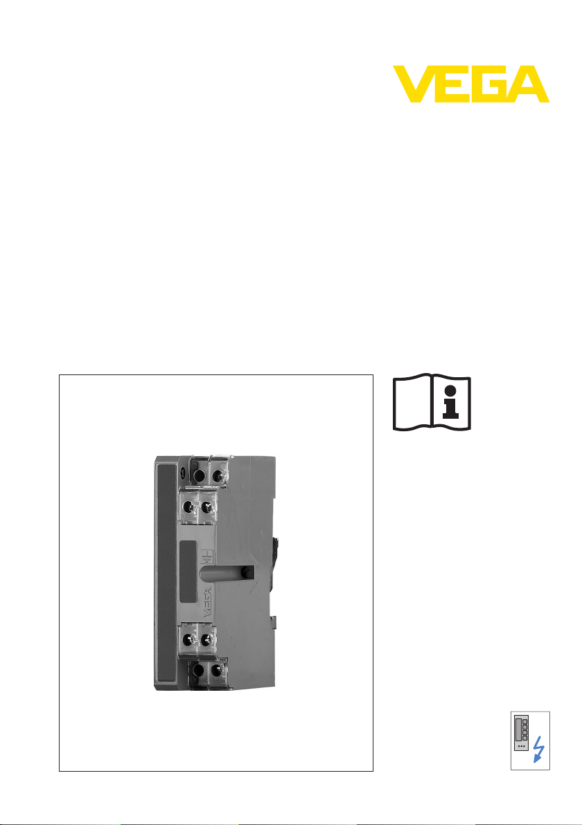
Overvoltage arrester
B61-300 FI
Document ID:
40489
ting
and protective instruments
Separa
Page 2

Contents
Conten
1 About this document
2 For your safety
3 Product description
4 Connecting to power supply
5 Maintenance and fault rectification
ts
1.1 Function. . . . . . . . . . . . . . . . . . . . . . . . . . . . . . . . . .
1.2 Target group . . . . . . . . . . . . . . . . . . . . . . . . . . . . . .
1.3 Symbolism used . . . . . . . . . . . . . . . . . . . . . . . . . . . .
2.1 Authorised personnel . . . . . . . . . . . . . . . . . . . . . . . .
2.2 Appropriate use . . . . . . . . . . . . . . . . . . . . . . . . . . . .
2.3 Warning about misuse . . . . . . . . . . . . . . . . . . . . . . .
2.4 General safety instructions . . . . . . . . . . . . . . . . . . . .
2.5 Safety label on the instrument . . . . . . . . . . . . . . . . . .
2.6 CE conformity . . . . . . . . . . . . . . . . . . . . . . . . . . . . .
2.7 Safety instructions for Ex areas . . . . . . . . . . . . . . . . .
2.8 Environmental instructions. . . . . . . . . . . . . . . . . . . . .
3.1 Structure . . . . . . . . . . . . . . . . . . . . . . . . . . . . . . . . .
3.2 Principle of operation . . . . . . . . . . . . . . . . . . . . . . . .
3.3 Packaging, transport and storage . . . . . . . . . . . . . . .
3.4 Installation in switching cabinet . . . . . . . . . . . . . . . . .
3.5 Mounting in housing . . . . . . . . . . . . . . . . . . . . . . . . .
4.1 Preparing the connection . . . . . . . . . . . . . . . . . . . . .
4.2 Connection steps for version with housing . . . . . . . . .
4.3 Wiring plan. . . . . . . . . . . . . . . . . . . . . . . . . . . . . . . .
5.1 Maintenance . . . . . . . . . . . . . . . . . . . . . . . . . . . . . .
5.2 Fault rectification . . . . . . . . . . . . . . . . . . . . . . . . . . .
5.3 Instrument repair . . . . . . . . . . . . . . . . . . . . . . . . . . .
3
3
3
4
4
4
4
4
5
5
5
6
6
7
9
11
12
12
13
15
15
15
6 Dismounting
6.1 Dismounting steps . . . . . . . . . . . . . . . . . . . . . . . . . .
6.2 Disposal . . . . . . . . . . . . . . . . . . . . . . . . . . . . . . . . .
7 Supplement
7.1 Technical data . . . . . . . . . . . . . . . . . . . . . . . . . . . . .
7.2 Dimensions . . . . . . . . . . . . . . . . . . . . . . . . . . . . . . .
Editing status: 2011-06-01
2 Overvolta
16
16
17
18
40489-EN-110616
ge arrester • B61-300 FI
Page 3
out this document
1 Ab
1 Abou
t this document
1.1 Function
This operating instructions manual provides all the information you
need for mounting, connection and setup as well as important
instructions for maintenance and fault rectification. Please read this
information before putting the instrument into operation and keep this
manual accessible in the immediate vicinity of the device.
1.2 Target group
This operating instructions manual is directed to trained qualified
personnel. The contents of this manual should be made available to
these personnel and put into practice by them.
1.3 Symbolism used
Inform
ation, tip, note
This symbol indicates helpful additional information.
Cauti
on: If this warning is ignored, faults or malfunctions can
result.
Warning: If this warning is ignored, injury to persons and/or serious
damage to the instrument can result.
Danger: If this warning is ignored, serious injury to persons and/or
destruction of the instrument can result.
applications
Ex
This symbol indicates special instructions for Ex applications.
40489-EN-110616
Overv
l List
The dot set in front indicates a list with no implied sequence.
à Action
Th
is arrow indicates a single action.
1 Sequence
Numbers set in front indicate successive steps in a procedure.
oltage arrester • B61-300 FI 3
Page 4

2 For
your safety
or your safety
2 F
2.1 Authorised personnel
All operations described in this operating instructions manual must be
carried out only by trained specialist personnel authorised by the plant
operator.
During work on and with the device the required personal protective
equipment must always be worn.
2.2 Appropriate use
The B61-300 FI is an overvoltage arrester for sensors and signal
conditioning instruments with mains power supply connected via a
fault-current circuit breaker (FI).
You can find detailed information on the application range in chapter
"Product description".
2.3 Warning about misuse
Inappropriate or incorrect use of the instrument can give rise to
application-specific hazards, e.g. vessel overfill or damage to system
components through incorrect mounting or adjustment.
2.4 General safety instructions
This is a high-tech instrument requiring the strict observance of
standard regulations and guidelines. The user must take note of the
safety instructions in this operating instructions manual, the countryspecific installation standards as well as all prevailing safety
regulations and accident prevention rules.
The instrument must only be operated in a technically flawless and
reliable condition. The operator is responsible for trouble-free
operation of the instrument.
During the entire duration of use, the user is obliged to determine the
compliance of the necessary occupational safety measures with the
current valid rules and regulations and also take note of new
regulations.
2.5 Safety label on the instrument
The safety approval markings and safety tips on the device must be
observed.
4 Overvolta
40489-EN-110616
ge arrester • B61-300 FI
Page 5

your safety
2 For
E conformity
2.6 C
This device fulfills the legal requirements of the applicable EC
guidelines. By attaching the CE mark, VEGA provides a confirmation
of successful testing. You can find the CE conformity declaration in the
download area of
www.vega.com.
2.7 Safety instructions for Ex areas
Please note the Ex-specific safety information for installation and
operation in Ex areas. These safety instructions are part of the
operating instructions manual and come with the Ex-approved
instruments.
2.8 Environmental instructions
Protection of the environment is one of our most important duties. That
is why we have introduced an environment management system with
the goal of continuously improving company environmental protection.
The environment management system is certified according to DIN
EN ISO 14001.
Please help us fulfil this obligation by observing the environmental
instructions in this manual:
l Chapter "Packaging, transport and storage"
l Chapter "Disposal"
40489-EN-110616
Overv
oltage arrester • B61-300 FI 5
Page 6
Typ B61 - 300 FI
OUT
IN
IP 20
max. 300 V AC/16 A
L1
N
L1
N
4
1
2
3
PE
PE
3 Produc
t description
pe of delivery
Sco
Constituent parts
3 Produc
t description
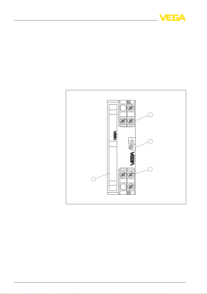
3.1 Structure
The scope of delivery encompasses:
l Overvoltage arrester B61-300 FI
l Documentation
- this operating instructions manual
The following illustration shows the configuration of the overvoltage
arrester B61-300 FI:
Fig. 1: Structure
1 Terminals Out (protected side)
2 Screw for carrier rail fastening
3 Terminals In (unprotected side)
4 Type label
Appli
cation area
3.2 Principle of operation
Voltage surges can be caused by indirect atmospheric discharges
(lightning strokes) or switching operations in the supply network.
Further causes can be inductive or capacitive couplings from other
electrical systems. Voltage peaks (transients) must be expected
especially when long power supply and signal cables are used.
6 Overvolta
of B61-300 FI
40489-EN-110616
ge arrester • B61-300 FI
Page 7

3 Produc
voltage surges can cause damage to sensors and signal
Such
t description
conditioning instruments.
VEGA overvoltage arresters reduce voltage surges on the supply or
signal cables to a safe level. They are designed for mounting on carrier
rail according to EN 50 022/EN 50 035 in the switching cabinet or in a
metal or plastic housing close to the sensor.
Func
tional principle
Packaging
Transport
Transport inspection
Varistors (voltage-dependent resistors) as well as overvoltage arresters (gas arresters) are used as protective elements for voltage
limitation.
As soon as the voltage reaches the response voltage of the protective
element increases, it becomes conductive and dissipates the energy
by briefly bridging the supply cables. When the voltage surge
subsides, the protective element returns to high-impedance status and
has no further influence on the supply circuit.
Due to this protective concept of B61-300 FI without energy dissipation
to ground, a connected fault-current circuit breaker is not triggered.
3.3 Packaging, transport and storage
The device was protected by packaging during transport. Its capacity
to handle normal loads during transport is assured by a test according
to DIN EN 24180.
The packaging of standard instruments consists of environmentfriendly, recyclable cardboard. For special versions, PE foam or PE foil
is also used. Dispose of the packaging material via specialised
recycling companies.
Transport must be carried out under consideration of the notes on the
transport packaging. Nonobservance of these instructions can cause
damage to the device.
The delivery must be checked for completeness and possible transit
damage immediately at receipt. Ascertained transit damage or
concealed defects must be appropriately dealt with.
Storage
40489-EN-110616
Overv
Up to the time of installation, the packages must be left closed and
stored according to the orientation and storage markings on the
outside.
Unless otherwise indicated, the packages must be stored only under
the following conditions:
l Not in the open
l Dry and dust free
l Not exposed to corrosive media
l Protected against solar radiation
l Avoiding mechanical shock and vibration
oltage arrester • B61-300 FI 7
Page 8

3 Produc
t description
Storage and transport
temperature
l Storag
e and transport temperature see chapter "Supplement -
Technical data - Ambient conditions"
l Relative humidity 20 … 85 %
8 Overvolta
40489-EN-110616
ge arrester • B61-300 FI
Page 9

1
1
3 Produc
t description
3.4 Instal
The overvoltage arrester is mounted in the switching cabinet on carrier
rails according to EN 50 022 (DIN rail) or EN 50 035 (C-rail). It is
fastened to the carrier rail with a screw located on its exterior. The
screw is marked with the symbol for functional ground. Depending on
the version, it may be galvanically connected to the ground terminal of
the overvoltage arrester (see circuit diagram in chapter "Wiring plan").
Fig. 2: Mounting
1 Carrier rail
lation in switching cabinet
on carrier rail according to EN 50 022 (DIN rail) 35 x 7.5 mm
40489-EN-110616
Overv
Fig. 3: Mounting
1 Carrier rail
Mounting steps
Proceed as follows:
oltage arrester • B61-300 FI 9
on carrier rail according to EN 50 035 (C-rail) 35 x 7.5 mm
Page 10

OUT
IN
IP 20
1
3 Produc
t description
1 Loos
Fig. 4: Mounting
1 Fixing screw
en fixing screw
on carrier rail
2 Place the overvoltage arrester onto the rail and let it snap in
3 Tighten fixing screw
10 Overvolta
40489-EN-110616
ge arrester • B61-300 FI
Page 11

1
2
4
3
OUT
IN
IP 20
1
2
3
OUT
IN
IP 20
3 Produc
t description
3.5 Mount
ing in housing
The overvoltage arrester is optionally available in a plastic or
aluminium housing. Make sure when mounting that the cable glands
point downward. Thus avoids water ingress.
Fig. 5: Mounting
1 Overvoltage arrester
2 PE terminal
3 Pressure compensation
4 Ground terminal
in Aluminium housing
40489-EN-110616
Overv
Fig. 6: Mounting
1 Overvoltage arrester
2 Pressure compensation
3 Ground terminal
in plastic housing
oltage arrester • B61-300 FI 11
Page 12

ecting to power supply
4 Conn
safety instructions
Note
Take note of sa-
fety instructions
for Ex applications
4 Conn
ecting to power supply
4.1 Preparing the connection
Always keep in mind the following safety instructions:
l Connect only in the complete absence of line voltage
Before starting setup make sure that the power supply corresponds to
the specifications on the type label.
For effective overvoltage protection, the cables between overvoltage
arrester and instrument should be as short as possible.
Dange
r:
Apart from the overvoltage arrester, a separate PE terminal is mounted
on the carrier rail in the aluminium housing. It is galvanically connected
with the carrier rail.
The ground conductor (PE) of the power supply cable must be led to
this PE terminal to reach protection ground for the aluminium housing.
The PE terminal on the overvoltage arrester must be free.
In
hazardous areas you must take note of the respective regulations,
conformity and type approval certificates of the sensors and power
supply units.
4.2 Connection steps for version with housing
Proceed as follows:
1 Loosen screws of the housing cover
2 Push the supply and connection cables through the cable gland
into the housing, strip approx. 1 cm (0.4 in) insulation from the
ends of the wires
3 Connect the wire ends L, N and PE according to chapter "Wiring
plan" to the terminals of the overvoltage arrester
4 With aluminium housing connect the wire end for PE to the green/
yellow PE terminal in the housing
5 Check all cable connections, especially the PE connection, to
make sure they are tightened sufficiently
6 Tighten the compression nuts of the cable glands. The seal ring
must completely encircle the cable
7 Tighten screws of the housing cover
The electrical connection is finished.
40489-EN-110616
12 Overvolta
ge arrester • B61-300 FI
Page 13

1
N
N
L1
L1
2
PE
PE
B61 - 300 FI
OUT
IN
IP 20
max. 300 V AC/16 A
2
4
3
1
L1
N
PE
PE
PE
L1
N
L1
N
ecting to power supply
4 Conn
diagram
Circuit
Wiring plan
4.3 Wir
Fig. 7: Circuit
ing plan
diagram overvoltage arrester B61-300 FI
1 Overvoltage arrester
2 Potential equalisation
Fig. 8: Wiring
plastic housing
plan overvoltage arrester B61-300 FI in the switching cabinet or
1 Mains supply through fault-current circuit breaker (FI)
2 Overvoltage arrester
3 Protected instrument
4 Carrier rail
40489-EN-110616
Overv
oltage arrester • B61-300 FI 13
Page 14

B61 - 300 FI
OUT
IN
IP 20
max. 300 V AC/16 A
PE
PE
L1
N
L1
N
2
3
5
4
1
L1
N
PE
ecting to power supply
4 Conn
Wiring plan with alumi-
housing
nium
Fig. 9: Wiring
plan overvoltage arrester B61-300 FI in aluminium housing
1 Mains supply through fault-current circuit breaker (FI)
2 Overvoltage arrester
3 PE terminal
4 Protected instrument
5 Carrier rail
14 Overvolta
40489-EN-110616
ge arrester • B61-300 FI
Page 15

aintenance and fault rectification
5 M
ction when malfunc-
Rea
occur
tions
Fault rectificat
24 hour service hotline
Reaction after fault rectifi
cation
ion
5 Maint
enance and fault rectification
5.1 Maintenance
If the instrument is used properly, no special maintenance is required
in normal operation.
5.2 Fault rectification
The operator of the system is responsible for taking suitable measures
to rectify faults.
The first measure to be taken is to check the input/output signal as well
as the power supply. In many cases, the causes can be determined
and faults can be quickly rectified.
On-site repair of B61-300 FI is not possible.
Should these measures not be successful, please call in urgent cases
the VEGA service hotline under the phone no. +49 1805 858550.
The hotline is available to you 7 days a week round-the-clock. Since
we offer this service world-wide, the support is only available in the
English language. The service is free of charge, only the standard
telephone costs will be charged.
Depending on the failure reason and measures taken, the steps
described in chapter "Set up" must be carried out again, if necessary.
40489-EN-110616
Overv
5.3 Instrument repair
If a repair is necessary, please proceed as follows:
You can download a return form (23 KB) from our homepage at
vega.com
By doing this you help us carry out the repair quickly and without
having to call back for needed information.
l Print and fill out one form per instrument
l Clean the instrument and pack it damage-proof
l Attach the completed form and, if need be, also a safety data
l Please ask the agency serving you for the address of your return
oltage arrester • B61-300 FI 15
under: "Downloads - Forms and certificates - Repair form".
sheet outside on the packaging
shipment. You can find the respective agency on our website
www.vega.com
under: "Company - VEGA worldwide"
www.
Page 16

6 Dismoun
ting
6 Dismou
nting
6.1 Dismounting steps
Take note of chapters "Mounting" and "Connecting to power supply"
and carry out the listed steps in reverse order.
6.2 Disposal
The instrument consists of materials which can be recycled by
specialised recycling companies. We use recyclable materials and
have designed the electronics to be easily separable.
WEEE directive 2002/96/EG
This instrument is not subject to the WEEE directive 2002/96/EG and
the respective national laws. Pass the instrument directly on to a
specialised recycling company and do not use the municipal collecting
points. These may be used only for privately used products according
to the WEEE directive.
Correct disposal avoids negative effects on humans and the environment and ensures recycling of useful raw materials.
Materials: see chapter "Technical data"
If you have no way to dispose of the old instrument properly, please
contact us concerning return and disposal.
16 Overvolta
40489-EN-110616
ge arrester • B61-300 FI
Page 17

7 Sup
plement
7 Supp
lement
7.1 Technical data
General data
Version Device for carrier rail mounting
Housing material Plastic (PPE)
Weight approx. 175 g (0.385 lbs)
Electrical characteristics
Nominal supply voltage 100 … 300 V AC/DC through fault-current circuit
Max. permissible current 16 A
Internal resistance < 0.01 Ω
Response voltage 500 V
Response time < 10
Nominal leakage current < 10 kA (8/20 µs)
Electromechanical data
Screw terminals for cable cross-section < 2.5 mm² (AWG 14)
Ambient conditions
Ambient temperature -40 … +60 °C (-40 … +140 °F)
Storage and transport temperature -40 … +70 °C (-40 … +158 °F)
Electrical protective measures
Protection rating
- unassembled IP 20
- In Aluminium or plastic housing IP 65
1)
breaker
-6
s
40489-EN-110616
Overv
1)
Reference
temperature 25 °C (77 °F).
oltage arrester • B61-300 FI 17
Page 18

84 mm
(3.31")
52 mm
(2.05")
25 mm
(0.98")
7 Suppl
7.2 D
ement
imensions B61-300 FI
Overvoltage arrester
Fig. 10: Dimensions B61-300 FI
18 Overvolta
40489-EN-110616
ge arrester • B61-300 FI
Page 19

Housing
ø5,5 mm
(0.22")
86 mm
(3.39")
120 mm
(4.72")
160 mm
(6.30")
77 mm
(3.03")
47 mm
(1.85")
50 mm
(1.97")
ø4,5 mm
(0.18")
82 mm
(3.23")
68 mm
(2.68")
72 mm
(2.84")
130 mm
(5.12")
116 mm
(4.57")
M 20 x 1,5
M 20 x 1,5
1
2
7 Sup
plement
Fig. 11: Dimensions B61-300 FI
1 Plastic
2 Aluminium housing
40489-EN-110616
Overv
housing
oltage arrester • B61-300 FI 19
Page 20

VEGA Grieshaber KG
ISO 9001
Am Hohenstein 113
77761 Schiltach
Germany
Phone +49 7836 50-0
Fax +49 7836 50-201
E-mail: info@de.vega.com
www.vega.com
Printing date:
statements concerning scope of delivery, application,
All
practical use and operating conditions of the sensors and
processing systems correspond to the information avail-
able at the time of printing.
© VEGA Grieshaber KG, Schiltach/Germany 2011
Subject to change without prior notice 40489-EN-110616
 Loading...