

Page 1
Operating Instructions
Lock fitting
ARV60.CB4 up to 64 bar
Level and Pressure
Page 2
Contents
Safety information ........................................................................ 2
Note Ex area ................................................................................ 2
1 Product description
1.1 Safety information ................................................................. 3
2 Mounting
2.1 Mounting procedure ............................................................ 4
3 Technical data
3.1 Technical data....................................................................... 6
3.2 Dimensions ........................................................................... 7
Contents
Safety information
Please read this manual carefully, and also take
note of country-specific installation standards
(e.g. the VDE regulations in Germany) as well
as all prevailing safety regulations and accident prevention rules.
For safety and warranty reasons, any internal
work on the instruments, apart from that involved in normal installation and electrical connection, must be carried out only by qualified
VEGA personnel.
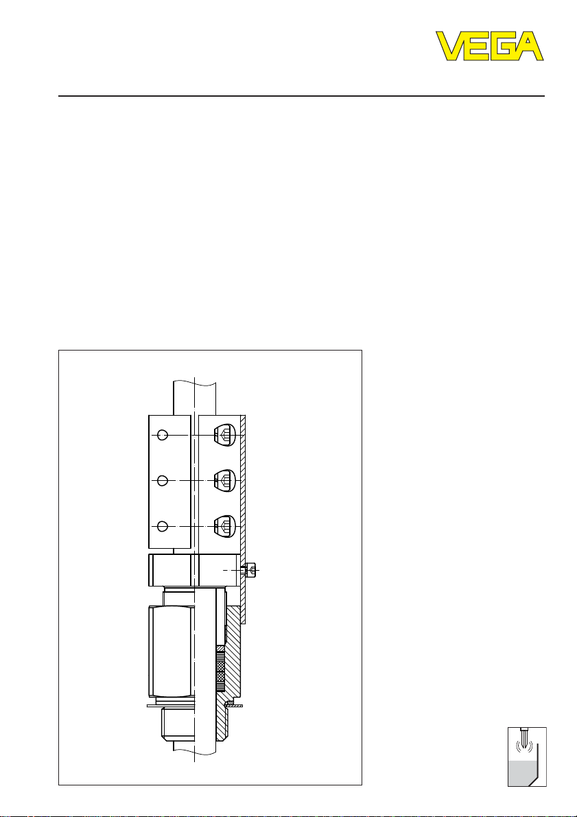
2 Lock fitting ARV60.CB4 up to 64 bar
Note Ex area
Please note the attached safety instructions
containing important information on installation
and operation in Ex areas.
These safety instructions are part of the operating instructions and come with the Ex approved instruments.
Page 3

Product description
1 Product description
The lock fitting ARV60.CB4 is a pressure-tight
clamping connection with G 1 A, G1½A or 1
NPT, 1½ NPT thread and can be used together with a level sensor in tube version
(e.g. VEGASWING 63). The tube extension of
the sensor must have a diameter of 21.3 mm
(DIN 2463/2462 D4-T3).
The wetted parts of the lock fitting are either
manufactured of steel 1.4435 (316L) or
Hastelloy C22 (2.4602).
The compression screw of the lock fitting
ARV60.CB4 radially squeezes a graphite
package consisting of four rings, which then
presses axially against the tube of the sensor. When properly mounted, a tight seal is
formed by the graphite package. The lock
fitting bracket secures the compression
screw and the clamp against unauthorised or
inadvertent loosening.
The lock fitting has the following approvals:
- tested by TÜV Rheinland acc. to
DruckbehV
- Zone 0 (ElexV) in combustible substances
of Ex group IIB up to max. 6 bar
-WHG
Note
If the lock fitting has to be removed for service or control purposes, you have to make
sure that the vessel is unpressurised. Switch
the power supply of the sensor off and remove all connection cables. Loosen the
mounting boss (6) with a spanner (SW 46).
Now you can remove the sensor together
with the lock fitting. It is therefore not necessary to readjust the switching point and the
lock fitting must not be completely disassembled.
1.1 Safety information
• Dismount the lock fitting only in
unpressurised condition.
• Only use suitable graphite packing rings
(article no. 2.26486). Make sure that the
graphite packing rings are not damaged.
Damaged rings do not ensure tightness. If
you are not sure, use new rings.
• Exclusively use approved hexagon socket
head screws DIN 912 M6 x 25 made of A470 acc. to AD regulation W2. The respective spring rings B6 must be made of A4
acc. to DIN 7980.
• Before screwing in, lubricate the thread of
the mounting boss, as well as the thread
and the head of the screws with a suitable
lubricant. The lubricant must be suitable for
the material combination 1.4435/1.4435
(stainless steel/stainless steel) or 2.4602/
2.4602 (Hastelloy/Hastelloy) and for a
temperature range of -50°C up to +250°C,
e.g. Varybond type NSS-16/7. The threads
come factory-treated with a suitable lubricant.
Lock fitting ARV60.CB4 up to 64 bar 3
Page 4

2 Mounting
Mounting
2.1 Mounting procedure
The numbers in brackets relate to the diagrams on the following pages.
• Loosen the holding screw (5) and remove
the lock fitting bracket (3).
• Unscrew the pressure screw (10) from the
mounting boss.
• Screw the mounting boss (6) with a resistant seal ring into the thread of your vessel
and tighten the mounting boss (6) with the
hexagon (SW 46).
• Now unpack the new laminated and graphite packing rings. The graphite packing
rings (8) have a plain cylindrical surface;
laminated packing rings (7) can be easily
recognised by their rougher cylindrical
surface and the laminated structure.
Make sure that the graphite packing rings
are not damaged. Damaged rings do not
ensure tightness. If you are not sure, use
new rings (article no. 2.26486).
• First of all, place one of the two laminated
packing rings (7) into the mounting boss
(6). Then place the two graphite packing
rings (8) on top, followed by the second
laminated packing ring (7).
• Place the metal compression ring (9) onto
the stack of packing rings.
• Screw the compression screw (10) with a
few turns from the top into the mounting
boss (6).
• Carefully remove grease, oil and dirt from
the extension tube of the sensor and the
surfaces of the clamp (11) and the compression screw (10) and insert the sensor
into the lock fitting. Move the tube to the
desired position and hold it firmly.
• Make sure that the sensor is in the correct
position (height). Please note that with the
height adjustment of the sensor, you also
determine the switching point.
• Tighten the compression screw (10) with a
torque of 80 ±10 Nm.
• Turn the compression screw (10) clockwise
until the hexagon surfaces of the compression screw (10) and the mounting boss (6)
are aligned (max. 1/6 turn).
• Tighten the screws (2) alternately with
uniform torque. Make sure that the gap
between clamp and compression screw is
in parallel. Fasten the screws up to a
torque of 7 ±2 Nm. The clamp (11) is
thereby pressed against the tube, fixing
the tube of the sensor in this position.
• Fasten the lock fitting bracket (3) with the
holding screw (5) and the spring ring (4)
laterally against the mounting boss (6).
This secures the compression screw and
the clamp screws against unintentional
loosening.
4 Lock fitting ARV60.CB4 up to 64 bar
Page 5

Mounting
ARV60.CB4 (64 bar)
11
10
1
2
3
4
9
5
7
8
8
7
6
1 Spring ring B6
2 Screw M6 x 25
3 Lock fitting bracket
4 Spring ring B4
5 Holding screw M4 x 10
6 Mounting boss
7 Laminated packing ring
8 Graphite packing ring
9 Compression ring
10 Compression screw
11 C la m p
Lock fitting ARV60.CB4 up to 64 bar 5
Article no. 2.26648
Page 6

Technical data
3 T echnical data
3.1 Tec hnical data ARV60.CB4
Thread size (mounting boss) G 1 A, G1½ A or 1 NPT, 1½ NPT
Tube diameter of the sensor ø 21.3 mm (DIN 2463/2462 D4-T3)
Material steel 1.4435 (316L) or Hastelloy C22 (2.4602)
Screws (2) hexagon socket screws DIN 912 M6 x 25
Holding screw (5) hexagon socket screws DIN 7964 M4 x 10
Product temperature -50°C … +250°C
Operating pressure
- ARV60.CA4… 64 bar
Tor qu e
- screws (2) 7 ±2 Nm
- compression screw (10) 80 ±10 Nm
Approvals:
material A4-70 acc. to AD regulation W2
accessory spring rings (1) B6
material A4 acc. to DIN 7980
material A4-70; accessory spring ring (4) B4
material A4 acc. to DIN 7980
note the nominal pressure of the sensor. The
lowest permissible operating pressure is valid.
DruckbehV
The TÜV Rheinland has tested the lock fitting ARV60.CB4 and approved it acc. to DruckbehV.
Ex, WHG
The lock fitting ARV60.CB4 in conjunction with suitable VEGA sensors (e.g. VEGASWING 63)
is approved acc. to WHG or for Ex-Zone 0. Note the corresponding certificates of the sensors.
6 Lock fitting ARV60.CB4 up to 64 bar
Page 7

Technical data
3.2 Dimensions
ø 21,3
SW 46
ca. 164
68
20
G1A, G1½A
1 NPT, 1½ NPT
ARV60.CB4 (64 bar)
Lock fitting ARV60.CB4 up to 64 bar 7
Page 8

VEGA Grieshaber KG
Am Hohenstein 113
D-77761 Schiltach
Phone (07836) 50-0
Fax (07836) 50-201
E-Mail info@de.vega.com
www.vega.com
ISO 9001
All statements concerning scope of delivery, application, practical
use and operating conditions of the sensors and processing systems correspond to the latest information at the time of printing.
Technical data to subject to alterations
26320-EN-030715
 Loading...