

Page 1

VEC-483K Owner’s Manual Voice Activated Tape Recorder Switch
INTRODUCTION
General Information: Ever wish you could edit the "dead air time" from tape
recordings of meetings, speeches, interviews, etc? Now you can do it while you
record with the VEC-483K Voice Activated Tape Recorder Switch Kit. With
voice activation, you save money by recording more information on each tape-and you save valuable listening time during playback because every inch of tape
is filled with information. In addition to voice-activating your recorder, the
VEC-483K helps you make better quality recordings because it places a highquality electret microphone near the sound source, and far away from the noisy
tape transport mechanism in your machine.
Circuitry: The VEC-483K has two parts. First, a sensitive electret microphone
picks up sound and sends it to your recorder via the external microphone jack.
Second, a high-gain op-amp samples the microphone signal, amplifies it, and
then detects it--using the detector level to drive a FET switch. This switch, in
turn, activates and pauses your recorder via the remote jack. Sensitivity and
hold-delay are both adjustable to your liking. The unit is internally powered by a
long-lasting 9-volt alkaline battery.
TOOLS AND SUPPLIES
Construction Area: Kit construction requires a clean, smooth, and well-lighted
area where you can easily organize and handle small parts without losing them.
An inexpensive sheet of white poster board makes an excellent construction
surface, while providing protection for the underlying table or desk. Diffused
overhead lighting is a plus, and a supplemental high-intensity desk lamp is
especially helpful for close-up work. Safety is always important! Use a suitable
high-temperature stand for your soldering iron, and keep the work area free of
clutter.
Universal Kit-building Tools: No special tools are required to complete this
kit beyond common items normally used for bench construction. We
recommend the following:
! Soldering Iron (grounded-tip and temperature-controlled preferred)
! High-temperature Iron Holder with Cleaning Sp onge
! Solder, 60/40 or 63/37 with rosin or "no-clean" flux (.031" dia. is good
size).
! Needle Nose Pliers or Surgical Hemostats
! Diagonal Cutters or "Nippy Cutters"
! Solder Sucker (squeeze or vacuum pump type), or Desoldering Braid
1
Page 2

VEC-483K Owner’s Manual Voice Activated Tape Recorder Switch
! Bright Desk Lamp
! Magnifying Glass
BEFORE YOU START BUILDING
Experience shows there are four common mistakes builders make. Avoid these,
and your kit will probably work on the first try! Here's what they are:
1. Installing the Wrong Part: It always pays to double-check each step. A 1K
and a 10K resistor may look almost the same, but they may act very
differently in an electronic circuit! Same for capacitors--a device marked
102 (or .001 uF) may have very different operating characteristics from one
marked 103 (or .01uF).
2. Installing Parts Backwards: Always check the polarity of electrolytic
capacitors to make sure the positive (+) lead goes in the (+) hole on the
circuit board. ICs have a notch or dot at one end indicating the correct
direction of insertion. Always double-check--especially before applying
power to the circuit!
3. Faulty Solder Connections: Inspect for cold-solder joints and solder
bridges. Cold solder joints happen when you don't fully heat the connection-or when metallic corrosion and oxide contaminate a component lead or pad.
Solder bridges form when a trail of excess solder shorts pads or tracks
together (see solder tips below).
4. Omitting or Misreading a Part: This is easier to do than you might think!
Always double-check to make sure you completed each step in an assembly
sequence.
Soldering Tips: Cleanliness and good heat distribution are the two secrets of
professional soldering. Before you install and solder each part, inspect leads or
pins for oxidation. If the metal surface is dull, sand with fine emery paper until
shiny. Allow the tip of your iron to contact both the lead and pad for about one
second (count "one-thousand-one") before feeding solder to the connection.
Surfaces must become hot enough for solder to flow smoothly. Feed solder to
the opposite side of the lead from your iron tip--solder will wick around the lead
toward the tip, wetting all exposed surfaces. Apply solder sparingly, and do not
touch solder directly to the hot iron tip to promote rapid melting. Keep a damp
sponge handy to wipe your so ldering tip on. This removes excess solde r, and
keeps the tip properly tinned. If the iron is going to sit idling for long periods,
wipe the tip, add some fresh solder, and unplug the iron.
Desoldering Tips: If you make a mistake and need to remove a part, follow
these instructions carefully! First, grasp the component with hemostats or
2
Page 3
VEC-483K Owner’s Manual Voice Activated Tape Recorder Switch
needle-nose pliers. Heat the pad beneath the lead you intend to extract, and pull
gently. The lead should come out. Repeat for the other lead. Solder may fill in
behind the lead as you extract it--especially if you are working on a double-sided
board with pla te-through holes. Should this hap pen, try heating the pad again
and inserting a common pin into the hole. Solder won't stick to the pin's
chromium plating. When the pad cools, remove the pin and insert the correct
component. For ICs or multiple-pin parts, use desoldering braid to remove
excess solder before attempting to extract the part. Alternatively, a low-cost
vacuum-bulb or spring-loaded solder sucker may be used. Parts damaged or
severely overheated during extraction should be replaced rather than reinstalled.
Work Habits: Kit construction requires the ability to follow detailed
instructions and, in many cases, to perform new and unfamiliar tasks. To avoid
making needless mistakes, work for short periods when you're fresh and alert.
Recreational construction projects are more informative and more fun when you
take your time. Enjoy!
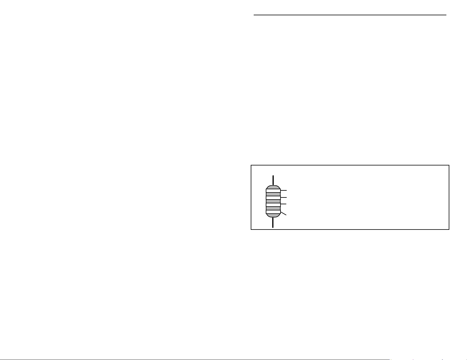
Sorting and Reading Resistors: The electrical value of resistors is indicated by
a color code (shown below). You don't have to memorize this code to work with
resistors, but you do need to understand how it works:
Resistor Color Code
Black = 0 (tens)
1st Digit
2nd Digit
Multiplier
Tolerence
(gold or silver)
When you look at a resistor, check its multiplier code first. Any resistor with a
black multiplier band falls between 10 and 99 ohms in value. Brown designates
a value between 100 and 999 ohms. Red indicates a value from 1000 to 9999
ohms, which is also expressed as 1.0K to 9.9K. An orange multiplier band
designates 10K to 99K, etc. To inventory resistors, first separate them into
groups by multiplier band (make a pile of 10s, 100s, Ks, 10Ks, etc.). Next, sort
each group by specific value (1K, 2.2K, 4.7K, etc). This procedure makes the
inventory easier, and also makes locating specific parts more convenient later on
during construction. Some builders find it especially helpful to arrange resistors
in ascending order along a strip of double-sided tape.
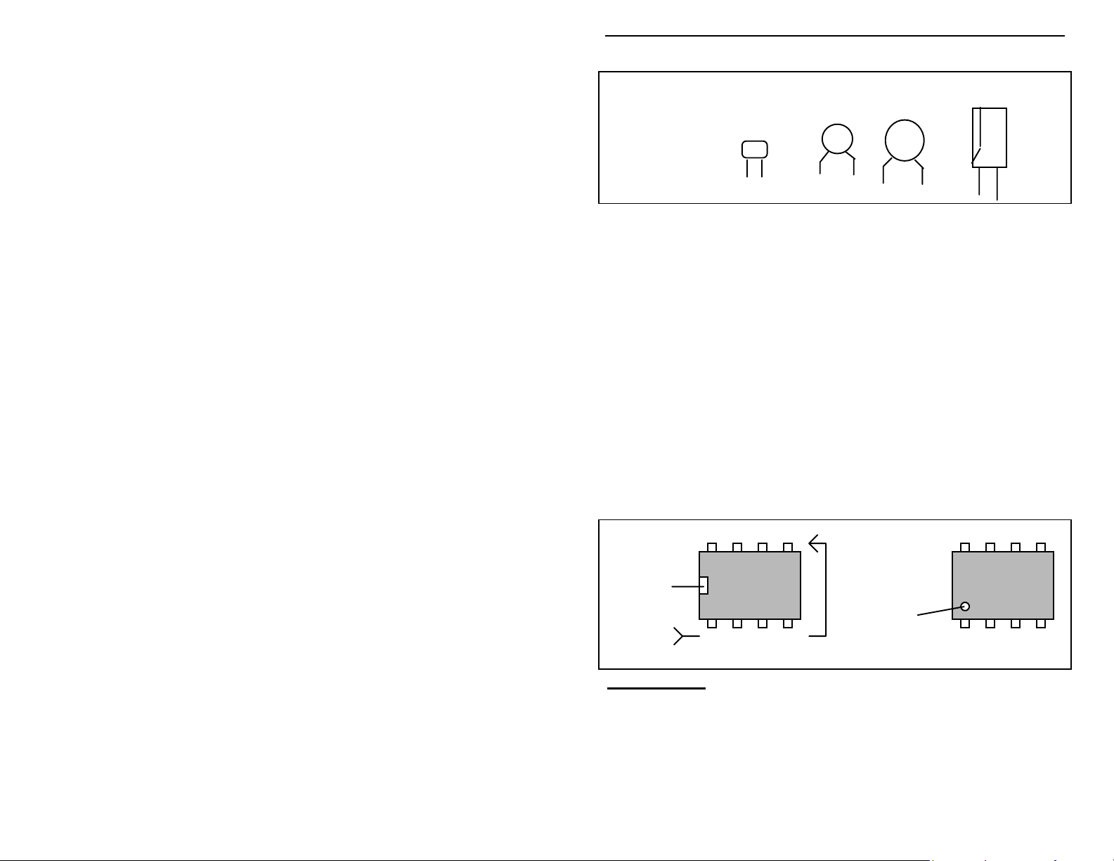
Reading Capacitors: Unlike resistors, capacitors no longer use a color code for
value identification. Instead, the value, or a 3-number code, is printed on the
body.
Brown = 1 (hundreds)
Red = 2 (K)
Orange = 3 (10K)
Yellow = 4 (100K)
Green = 5 (1Meg)
Blue = 6
Violet = 7
Gray = 8
White = 9
Silver = 10%
Gold = 5%
3
Page 4
VEC-483K Owner’s Manual Voice Activated Tape Recorder Switch
Value Code
10 pF = 100
100 pF = 101
1000 pF = 102
.001 uF = 102*
.01 uF = 103
.1 uF = 104
As with resistors, it's helpful to sort capacitors by type, and then to arrange them
in ascending order of value. Small-value capacitors are characterized in pF (or
pico-Farads), while larger values are labeled in uF (or micro-Farads). The
transition from pF to uF occurs at 1000 pF (or .001 uF)*. Today, most
monolithic and disc-ceramic capacitors are marked with a three-number code.
The first two digits indicate a numerical value, while the last digit indicates a
multiplier (same as resistors).
Electrolytic capacitors are always marked in uF. Electrolytics are polarized
devices and must be oriented correctly during installation. If you become
confused by markings on the case, remember the uncut negative lead is slightly
shorter than the positive lead.
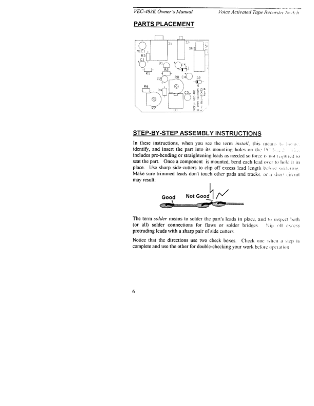
Integrated Circuits: Proper IC positioning is indicated by a dot or square
marking located on one end of the device. A corresponding mark will be silkscreened on the PC board and printed on the kit's parts-placement diagram. To
identify specific IC pin numbers for testing purposes, see the diagram below.
Pin numbers always begin at "1" at the keyed end of the case and progress along
the device, as shown:
Multilayer
(270 pF)
271
Ceramic Discs
(.001 uF) (.1 uF)
102
104
Electrolytic
1 uF
|
1uF
|
35V
+
-
8 7 6 5
Installation
Key
1 2 3 4
Pin Numbers
Installation
Key
PARTS LIST
Your kit should contain all of the parts listed below. Please identify and
inventory each item on the checklist before you start building. If any parts are
missing or damaged, refer to the manual's warranty section for replacement
instructions. If you can't positively identify an unfamiliar item on the basis of the
information given, set it aside until all other items are checked off. You may
4
Page 5

VEC-483K Owner’s Manual Voice Activated Tape Recorder Switch
then be able to identify it by process of elimination. Finally, your kit will go
together more smoothly if parts are organized by type and arranged by value
ahead of time. Use this inventory as an opportunity to sort and arrange parts so
you can identify and find them quickly.
""""
Qty Part Description Designation VEC P/N
#
2 1K resistor (brown-black-red) R3, R4 100-3100
#
2 10K resistor (brown-black-orange) R1, R2 100-4100
#
1 47K resistor (yellow-violet-orange) R6 100-4470
#
2 500K trimpot R7, R8 133-5500
#
3 1 uF electrolytic capacitor C1, C4, C5 270-4100-2
#
2 10 uF electrolytic capacitor C2, C3 270-5100-1
#
2 1N4148 diode D1, D2 300-4148
#
1 2N7000 plastic FET transistor Q1 305-7000
#
1 LM358 op-amp (8-pin) U1 324-0358
#
1 Microphone element, electret MIC1 410-1092
#
1 2P2T mini power switch SW1 504-2022
#
1 3.5mm stereo jack J1 601-5005
#
1 2.5mm mono jack J2 601-4009
#
1 9V battery snap BAT1 730-3005
#
1 8 pin IC socket for U1 625-0008
#
1 Plastic wire tie 745-2149
#
1 VEC-483 printed circuit board 861-VEC483
#
1 Owner’s Manual 925-VEC483K
PARTS PLACEMENT
5
Page 6
Page 7

VEC-483K Owner’s Manual Voice Activated Tape Recorder Switch
This kit has 5 fixed-value resistors. Mount these now, starting with the smallest
value and moving to the largest. Before mounting each one, carefully bend both
leads close to the resistor body to form right-angles, as shown below:
.4"
Locate two (2) 1K resistors (brown-black-red).
# # 1.$Install 1K at R3 and solder.
# # 2.$Install 1K at R4 and solder.
Locate two (2) 10-K resistors (brown-black-orange).
# # 3.$Install 10 K at R1 and solder.
# # 4.$Install 10 K at R2 and solder.
# # 5.$Find the 47-K resistor (yellow-violet-orange). Install at R6 and solder.
The next two (2) items are 500-K trimpots (black, screw adjustment in the
center, 3 pins). When you install each trimpot, make sure it is seated firmly
against the PC board with all three leads protruding.
# # 6.$Install a 500-K trimpot at R7 and solder.
# # 7.$Install a 500-K trimpot at R8 and solder.
There are five electrolytic capacitors in your kit. Electrolytic caps are
polarized and must be installed the correct way in order to work. Each
capacitor's plus (+) mounting hole is marked on both the circuit board and parts
placement diagram. If the markings on the capacitor body are unclear, the plus
(+) lead is always the longer of the two.
+
Plus Lead
Locate three (3) 1-uF electrolytic capacitors. Observing polarity:
# # 8.$Install 1 uF at C1 and solder.
# # 9.$Install 1 uF at C4 and solder.
7
Page 8

VEC-483K Owner’s Manual Voice Activated Tape Recorder Switch
# # 10.$Install 1 uF at C5 and solder.
Locate two (2) 10-uF electrolytic capacitors. Observing polarity:
# # 11.$Install 10 uF at C2 and solder.
# # 12.$Install 10 uF at C3 and solder.
Now, find two (2) 1N4148 silicon diodes (glass body). Like capacitors, diodes
are polarized devices that must be installed correctly. Always look for the
banded end when installing--and align this with the banded end shown on the PC
layout.
# # 13.$Install a 1N4148 at D1 and solder.
# # 14.$Install a 1N4148 at D2 and solder.
Locate the 2N7000 plastic transistor. Like the electrolytic caps, transistors must
be oriented correctly to work properly.
2N7000
# # 15.$Install the 2N7000 FET at Q1 and solder.
The ICs in your kit will be installed in a IC socket. Like the IC itself, the socket
is keyed at one end to indicate proper positioning. During installation, orient the
socket so the notch corresponds to the key on the PC layout.
Key
Key
When installing the socket, make sure all pins enter the mounting holes and
appear on the opposite side of the PC board (it's easy to fold one or more under).
8
Page 9

VEC-483K Owner’s Manual Voice Activated Tape Recorder Switch
Also, when soldering, make sure the socket remains flat against the board
surface.
# # 16.$Find the 8-pin IC socket. Orient to U1, install, and solder all pins.
Next, align the LM358 IC with the socket, matching its key with the socket key.
When you install, press in slowly--making sure all pins go into the socket holes
and none fold over under the device.
# # 17.$Observing the key, install the LM358 at U1.
Your kit co ntains a miniat ure DPDT switch. Some versions r equire install ation
of a plastic clip-on support at the front of the switch body. This piece relieves
stress on the pins and ensures level seating during installation. If your parts kit
contains this piece, install as shown:
# # 18.$Install the DPDT mini power switch at SW1
Locate the 9-V battery snap clip, and note the red+ lead and black- lead.
# # 19.$Install the red lead at BAT1 (+) and solder.
# # 20.$Install the black lead at BAT1 (-) and solder.
Find the oversized hole slightly to the rear of the BAT1 connections. The plastic
tie-wrap supplied with your kit will be installed here to bind the two battery
leads to the PC board. This will help prevent lead breakage later on.
Tie-wrap
+
SW1
-
9
Page 10

VEC-483K Owner’s Manual Voice Activated Tape Recorder Switch
# # 21.$Locate the tie-wrap and install as shown.
Your kit has two (2) min-phono jacks. The larger of the two is a 3.5 mm stereo
jack, and the smaller is a 2.5 mm mono jack. When installing jacks, make sure
the case sets firmly against the PC board surface before soldering.
# # 22.$Install the 3.5 mm jack (larger) at J1 and solder.
# # 23.$Install the 2.5 mm jack (smaller) at J2 and solder.
Finally, locate the electret condenser microphone element (MIC1) and observe
the leads. One is grounded to the case by a bridge of metal, while the other is
not. The gro und ed le ad must co r re sp ond with the groundp la ne mounting hole on
the PC board.
"Hot" Side
Ground Side
Element
Space element above board
so leads protrude
about .1" through
PC board.
When positioning the mic element, space as far as possible above the surface of
the PC board. Leads should protrude only enough to ensure a good solder
connection.
# # 24.$Observing polarity, install the electret mic element at MIC1 and solder
in place.
This concludes construction of your VEC-483K Voice-Activated Tape Switch.
Before moving on, give your kit a thorough QC (quality control) inspection.
This will help you discover accidental assembly errors that might prevent it from
working properly--or that might cause damage to sensitive parts when you apply
power. Follow this procedure:
1. Compare parts locations with the parts-placement diagram. Was each part
installed where it is supposed to be? Was the correct value used? Start at
one side of the board and work your way across in an organized pattern.
2. Inspect the solder side of the board for cold-solder joints and solder bridges
between tracks or pads. Use a magnifying glass to obtain a clear view of the
track area. If you suspect a solder bridge, hold the board in front of a bright
light for a better view. All joints should be smooth and shiny, indicating
good solder wetting and flow. Resolder any beaded or dull-appearing
connections. Also, check the front-panel jacks, switches, and connectors for
defective solder connections.
3. Finally, check electrolytic capacitors and diodes for correct polarity. Does
the plus (+) polarity symbol on the part agree with the pictorial and with the
10
Page 11

VEC-483K Owner’s Manual Voice Activated Tape Recorder Switch
pattern on the PC board? Is the banded end of each diode positioned
correctly? Were the IC and transistor installed correctly?
Be sure to correct all errors before continuing.
TESTING AND ALIGNMENT
Before you can test and operate your unit, you'll need two patch cords to connect
the VEC-483K to your recorder. These may be purchased at Radio Shack, or
you may make them up as shown:
3.5 stereo plugs
"External microphone" line to recorder
2.5 mm mono Plugs
"Remote" line to recorder
These mic and switch lines may be any convenient length, but shielded cable
should be used for the microphone cable if it's more than a foot or so long.
Unshielded wire is okay for the remote line. Connect the VEC-483K to your
tape recorder as follows:
VEC-483K
Pwr
J2
Mic
J1
Mic Remote
The PC board has two set-up adjustments. For no w, adjust trimpots R7 and R8
for mid-scale (12:00) using a small screwdriver. Once you're sure the unit is
11
Page 12

VEC-483K Owner’s Manual Voice Activated Tape Recorder Switch
working properly, you may set these more precisely for your personal
preference.
1. Put SW1 in the Off position (switch button out).
2. Install a fresh 9-volt alkaline battery on the battery snap clip.
3. Press SW1 On (switch button in).
4. Place recorder in "record" mode.
If there's no sound present, the tape transport should not remain on with the
record button is depressed. If it does remain on, check for construction
errors--especially around U1. If not, proceed.
5. Whistle into the microphone.
The tape transport should start rolling. If it doesn't, look for errors around
D1, D2 and Q1.
After a second or so of silence, the tape should shut off again, automatically.
If it doesn't, look for errors around delay control R8. If the tape starts and
stops automatically, your unit is working properly.
Now is a good time to set up the Sensitivity and Delay controls.
Sensitivity: The Sensitivity of your VEC483K is controlled by R7. This sets
the "start-up" threshold for activating the transport. Under noisy conditions,
reducing sensitivity prevents stray background noise from starting the tape
transport. If there's little background noise and a weak sound source, increased
sensitivity is best.
Delay: The Delay (or hold) is controlled by R8. This sets the period of time the
transport stays on after the sound stops. A short delay is best when the sound
source is "up close and personal". A longer delay works best for variable sounds
that may not always be strong eno ugh to hold the switching circuit on.
Once you are satisfied that your unit is operating properly and adjusted to your
needs, you may mount it in the enclosure of your choice. The VEC483KC is
made especially for your unit, and is highly recommended.
OPERATING INSTRUCTIONS
Using Your Recorder Switch: Detailed operating instructions are contained in
the previous section. In general, all you need to do is plug in your unit
(microphone and remote), and turn the MFJ-483K on. If playback sounds
"broken" because the transport drops out during words or phrases, increase
12
Page 13

VEC-483K Owner’s Manual Voice Activated Tape Recorder Switch
sensitivity (R7) until the recorder remains on. If playback sounds "choppy"
because of constant stopping and starting, increase delay (R8) to add more
natural spacing between words and phrases.
IN CASE OF DIFFICULTY
Before seeking outside assistance, check below for a possible solution:
Does not turn on: Check battery condition, snap clip, and power leads. Also,
make sure lead polarity is correct (red to +, black to GND). Make sure power
switch is "on".
Transport Stays on: Setting of R7 or R8 too high, remote cable shorted.
Transport Won't Start: Setting for R7 or R8 too low, remote cable open.
If these checks fail to uncover the problem, repeat the "QC" check one more
time. Service records show that, for most malfunctioning kits, outright
component failure is relatively rare. In most cases, the culprit is a misplaced
part, reverse-polarized capacitor, improperly installed IC, or a faulty solder
connection. If, despite your best effort, you cannot solve the problem, kit repair
services are available through V ectronics. See the warranty on the inside front
cover for complete instructions.
13
Page 14

VEC-483K Owner’s Manual Voice Activated Tape Recorder Switch
THEORY OF OPERATION
Electret microphone MIC1 picks up sound and generates an audio signal which
loops through to microphone output jack J1. Along the way a sample of the
audio signal is picked up by U1a, an op-amp configured as a variable gain audio
amplifier. Stage gain is established by Sensitivity control R7. U1's amplified
AF output signal is detected by D1/D2, converted to a dc level, and fed to the
gate of Q1. When sufficient voltage is developed across the detector, FET
switch Q1 conducts and pulls the recorder's "remote" line to ground--providing a
current path for activation of the transport motor. To create the unit's "delay"
function, a RC circuit on the gate of Q1 stores detector voltage and holds the
gate voltage "high" at a decaying rate. The time constant of this circuit is
adjustable by Delay Control R8. Q1 has sufficient current handling capacity to
operate a wide range of small-recorder transport motors.
14
Page 15

Page 16

VEC-483K Owner’s Manual Voice Activated Tape Recorder Switch
ENCLOSURE
To install your Voice-Activated Tape Recorder Switch in the VEC-483KC
matching enclosure follow these instructions (read all instructions before
beginning ... take your time):
1. Find the front panel decal and trim. Be sure to leave excess decal material
around the edges. Put the front panel decal on. T his is done by: a.)
Remove all debris and oil from the face plate. This should be done using a
piece of cloth and alcohol. b.) Remove the crack and peel to expose the
adhesive. c.) Place the decal on the front panel without securing it
completely. d.) Gently rub the alignment circles with your finger--if the
circles are centered in the enclosure holes (also check the corner alignment
marks) secure the decal by rubbing and removing all air bubbles. e.) If the
alignment circles are not centered, adjust the decal accordingly, then secure.
f.) Use a penknife, o r small Exact o
from the adhesive side) and cut out the component holes (cut from the
description side).
2. Now insert the PC board. This must be done by: a.) Insert the front of the
PC board into the metal faceplate with the jacks in their respective holes. b.)
Place the nuts onto the jacks and tighten. Ensure that the switch and the
microphone are aligned properly. c.) Install the red switch cap on the power
switch (SW1).
TM
knife, to cut away the unused edges (cut
3. Slide the face plate in the slots at the end of the bottom portion of the
enclosure. Loop the battery snap through to the battery compartment. Now
place the top portion over the bottom ensuring that the face plate slides into
the slots. Secure the two enclosure portions together with the two mounting
screws.
4. Finally, place a 9V battery into the battery compartment and attach to the
battery snap. Make sure the power switch is off before installing the battery.
16
Page 17

 Loading...