


|
TABLE OF CONTENTS |
|
1.0 INTRODUCTION ................................................................................................................................................ |
1 |
|
1.1 |
A Quick Word about Accuracy ............................................................................................................... |
1 |
1.2 |
Typical Uses ............................................................................................................................................ |
2 |
1.3 |
Frequency Range ..................................................................................................................................... |
4 |
2.0 POWER SOURCES ............................................................................................................................................. |
4 |
|
2.1 |
External Power Supply ............................................................................................................................ |
4 |
2.2 |
Using Internal Batteries ........................................................................................................................... |
4 |
2.3 |
Using Rechargeable “AA” Type Batteries .............................................................................................. |
5 |
2.4 |
Using Conventional “AA” Drycell Batteries........................................................................................... |
5 |
2.5 |
“Power Saving” Mode (sleep mode) ....................................................................................................... |
6 |
3.0 MAIN MENU AND DISPLAY............................................................................................................................ |
6 |
|
3.1 |
General Connection Guidelines............................................................................................................... |
6 |
3.2 |
Power-up Display .................................................................................................................................... |
7 |
3.3 |
Main MODE descriptions........................................................................................................................ |
7 |
3.4 |
Blinking “VOLTAGE LOW” display warning ....................................................................................... |
8 |
4.0 MAIN (OR OPENING) MODE ........................................................................................................................... |
8 |
|
4.1 |
General Connection Guidelines............................................................................................................... |
9 |
4.2 |
Antenna SWR .......................................................................................................................................... |
9 |
4.3 |
Coax Loss ................................................................................................................................................ |
11 |
4.4 |
Capacitance.............................................................................................................................................. |
11 |
4.4 |
Inductance................................................................................................................................................ |
12 |
5.0 ADVANCED OPERATION ................................................................................................................................ |
14 |
|
5.1 |
Forward.................................................................................................................................................... |
14 |
5.2 |
General Connection Guidelines............................................................................................................... |
15 |
5.3 |
(Magnitude of) Impedance mode............................................................................................................ |
15 |
5.4 |
Return Loss and Reflection Coefficient mode ........................................................................................ |
16 |
5.5 |
Distance to Fault mode ............................................................................................................................ |
16 |
5.6 |
Resonance Mode...................................................................................................................................... |
18 |
5.7 |
Percentage Transmitted Power ................................................................................................................ |
18 |
6.0 ADJUSTING SIMPLE ANTENNAS................................................................................................................... |
19 |
|
6.1 |
Dipoles..................................................................................................................................................... |
19 |
6.2 |
Verticals................................................................................................................................................... |
19 |
6.3 |
Tuning a simple antenna.......................................................................................................................... |
19 |
7.0 TESTING AND TUNING STUBS AND TRANSMISSION LINES .................................................................. |
20 |
|
7.1 |
Testing Stubs ........................................................................................................................................... |
20 |
7.2 |
Velocity Factor of Transmission Lines ................................................................................................... |
21 |
7.3 |
Impedance of Transmission Lines or Beverage antennas........................................................................ |
22 |
7.4 |
Adjusting Tuners ..................................................................................................................................... |
23 |
7.5 |
Adjusting Amplifier Matching Networks................................................................................................ |
23 |
7.6 |
Testing RF Transformers......................................................................................................................... |
24 |
7.7 |
Testing Baluns ......................................................................................................................................... |
24 |
7.8 |
Testing RF Chokes .................................................................................................................................. |
25 |
8.0 TECHNICAL ASSISTANCE............................................................................................................................... |
25 |
|

SWR-584B Instruction Manual |
HF/VHF SWR Analyzer |
1.0 INTRODUCTION
Attention: Read section 2.0 before attempting to use this product. Incorrect power supply voltages or excessive external voltages applied to the ANTENNA connector will damage this unit.
Description
The SWR-584B RF analyzer is a compact battery powered RF impedance analyzer. This unit combines four basic circuits; a 1.8-170 MHz variable frequency oscillator, a frequency counter, a 50 ohm RF bridge, and an eight-bit micro-controller. This unit makes a wide variety of useful antenna or impedance measurements, including coaxial cable loss and distance to an open or short.
Primarily designed for analyzing 50 ohm antenna and transmission line systems, the SWR-584B also measures RF impedances between a few ohms and several hundred ohms. It also functions as a signal source and frequency counter. The frequency range of impedance measurement is 1.8 to 170 MHz, in six overlapping bands.
1.1 A Quick Word about Accuracy
Inexpensive impedance meters have limitations. The following text details several common problems and reasons they occur.
Measurement errors. Unreliable readings are rooted in three primary areas:
1.) Signal ingress from external RF sources, usually strong AM broadcast stations. 2.) Diode detector and A/D converter errors.
3.) The impedance of connectors, connections, and lead lengths.
Virtually all low cost impedance meters use broad-band voltage detectors. The reason virtually all analyzers use broadband detectors is cost. Narrow band detectors are very expensive, since the detector system would have to use at least one selective gain-stable receiver. Narrow band detectors would price antenna and impedance analyzers far outside the price range of most casual users.
Broadband detectors are sensitive to out-of-band external voltages, and solutions to most out-of-band interference are not simple. Common low-pass or band-pass filters behave like small transmission lines of varying impedances on different frequencies. Low-pass or high-pass filters change impedance and SWR readings, just as an additional section of transmission line would. This modification of impedance caused by filters severely limits their usefulness.
One solution to this problem (often mentioned by users) is to increase internal generator power. Unfortunately the power required to operate a clean, harmonic-free broadband VFO system greatly reduces battery life. In this unit, more than 70% of the total battery drain (-150 mA) is used to produce the low harmonic distortion test signal.
Most RF interference problems occur on lower frequencies, since high power AM broadcast signals couple well into large antennas (especially 160 meter verticals). MFJ offers an adjustable filter that attenuates all offfrequency signals while having virtually no small effect on measurements between 1.8 and 30 MHz. Properly used, this adjustable filter reduces external interference while having nearly no measurable effect on desired measurements.
2

SWR-584B Instruction Manual |
HF/VHF SWR Analyzer |
Component limitations are another source of inaccuracy. Diodes detecting very small voltages are nonlinear. The accuracy of the SWR-584B is enhanced by the use of special microwave zero-bias Schottky detectors with matching compensating diodes. Each unit is individually compensated to provide the best possible linearity with both high and low impedance loads, making the A/D converter's 1/2 percent resolution the primary limitation.
Connection lengths are another problem. Connection lengths between components in the bridge and the bridge and output connector upset readings, especially when the impedance is very high or very low. The SWR584B minimizes this problem by using surface mount low capacitance microwave components with nearly zero lead length.
Unlike instruments that present readings outside the reliable range as exact numbers, the SWR-584B gives a display warning. If (Z>650) appears on the display, the impedance is greater than 650 ohms and outside the reliable instrument range.
1.2 |
Typical Uses |
|
The SWR-584B can be used to adjust, test, or measure the following: |
||
Antennas: ................................... |
SWR, impedance, reactance, resistance, resonant frequency, and bandwidth |
|
Antenna tuners:.......................... |
SWR, bandwidth, frequency |
|
Amplifiers:................................. |
Input and output matching networks, chokes, suppressors, traps, and components |
|
Coaxial transmission lines:........ |
SWR, length, velocity factor, approximate Q and loss, resonant frequency, and |
|
|
|
impedance |
Filters: |
........................................ |
SWR, attenuation, and frequency range |
Matching ..........or tuning stubs: |
SWR, approximate Q, resonant frequency, bandwidth, impedance |
|
Traps: ......................................... |
|
Resonant frequency and approximate Q |
Tuned Circuits: .......................... |
Resonant frequency and approximate Q |
|
Small capacitors:........................ |
Value and self-resonant frequency |
|
RF chokes ..........and inductors: |
Self resonant frequency, series resonance, and value |
|
Transmitters ......and oscillators: |
Frequency |
|
The SWR-584B measures and displays the following:
Cable length (feet) |
Impedance phase (degrees) |
Resonance (MHz) |
Cable Loss (dB) |
Inductance (uH) |
Return loss (dB) |
Capacitance (pF) |
Reactance or X (ohms) |
Signal Frequency (MHz) |
Impedance or Z magnitude (ohms) |
Resistance or R (ohms) |
SWR (referenced to 50 ohms) |
The SWR-584B is useful as a non-precision signal source. It provides a relatively pure (harmonics better than -25 dBf) signal of approximately 3 Vpp (approximately 20 milliwatts) into 50 ohm loads. The SWR-584B internal source impedance is 50 ohms.
Note: A more complete description of the SWR-584B's features and proper measurement methods can be found by reading the sections on the particular measurement you wish to make. Consult the table of contents for the various applications.
3

SWR-584B Instruction Manual HF/VHF SWR Analyzer
1.3 Frequency Range
The FREQUENCY switch selects the following internal oscillator frequency ranges. (A small overlap outside each range is provided):
1.8 - 4 MHz 27 - 70 MHz 4 - 10 MHz 70 - 114 MHz 10 - 27 MHz 114170 MHz
2.0 POWER SOURCES
+Read this section before connecting this device to any power source. Improper connections or incorrect voltages may cause damage to this product!
2.1 External Power Supply
MFJ has an optional power supply, the MFJ-1315, that satisfies all external supply requirements. We recommend only using this supply.
Voltage must be more than 11 volts, and preferably less than 16 volts, when the unit is on and operating. Maximum “sleep mode” and “OFF” voltage (when the power supply is lightly loaded by this unit) is 18 volts. The supply must be reasonably well filtered. The supply must not have a grounded positive lead!
The SWR-584B can be used with an external low voltage dc supply’s (MFJ-1315 AC adapter recommended). The ideal supply voltage is 14.5 volts dc, but the unit will function with voltages between 11 and 18 volts. The current demand is 150 mA maximum. (Be sure you read the battery instructions if you use also install batteries!)
The SWR-584B has a recessed 2.1 mm power-type receptacle near the RF connectors. This receptacle is labeled
“POWER 12VDC”.
The outside conductor of the POWER receptacle is negative, the center conductor positive.
Inserting a power plug in the “POWER 12VDC” receptacle disables internal batteries as a power source. Internal batteries, although disabled for operating power by inserting a power supply plug, can still be trickle charged.
WARNING: REVERSE POLARITY OR EXCESSIVE VOLTAGE CAN DAMAGE OR DESTROY THE SWR-584B. NEVER APPLY MORE THAN 18 VOLTS, NEVER USE AC OR POSITIVE GROUND SUPPLIES!
2.2 Using Internal Batteries
When batteries are initially installed, a small black-plastic internal jumper must be re-positioned or checked for proper position. The battery setting jumper is located inside the unit at the top of the printed circuit board near the area of the OFF-ON switch and power connector. This jumper is accessed by removing eight screws along the both sides of the SWR-584B. After the cover mounting screws are removed, remove the entire back cover. The black plastic jumper fits over two of three adjacent pins. It must be properly positioned for the type of battery used (either rechargeable or non-rechargeable).
4
SWR-584B Instruction Manual |
HF/VHF SWR Analyzer |
For battery replacement, batteries are accessed by removing the SWR-584B’s small rear panel. The battery cover is secured by 2 Phillips head screws.
2.3 Using Rechargeable “AA” Type Batteries
CAUTION: Avoid using external power sources having less than 13 volts if rechargeable batteries are installed. If external supply voltage is too low, the charger will not work properly and batteries will eventually discharge. We recommend charging batteries with the SWR-584B power switch off, with enough charging time to establish full battery charge (at least ten hours).
When using rechargeable batteries, an external supply that remains between 14 and 18 volts should be used. Typical battery charging current is 10-20 mA through an internal charging system. The internal charger trickle charges internal batteries any time a proper external voltage is applied, even when the SWR-584B is turned off. The MFJ-1315 supply fulfills all power supply requirements.
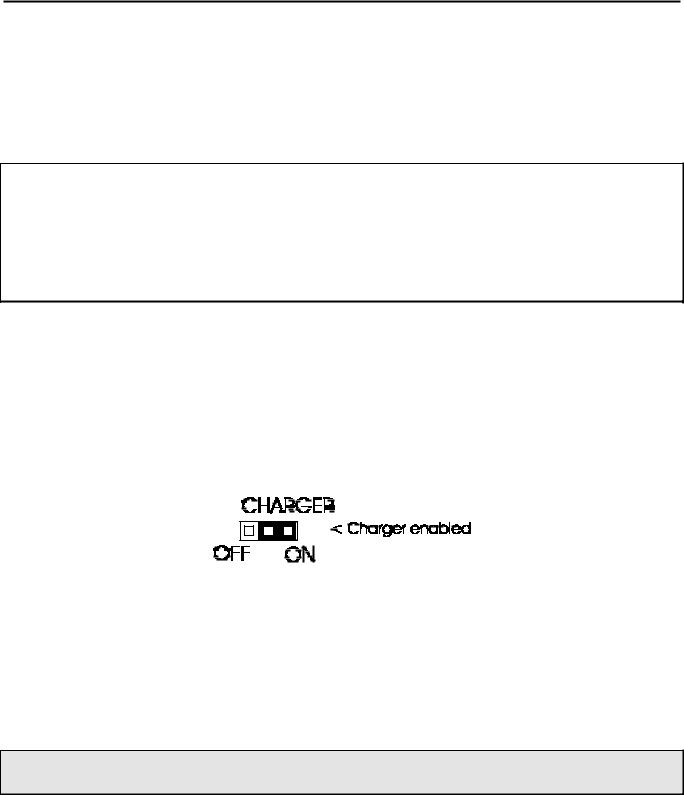
When using rechargeable batteries, the internal black plastic jumper located inside the cover (near the external power jack on the circuit board) must be set to the proper position. If it is not set to the proper position, the batteries will not charge. With rechargeable batteries, the internal charger jumper located on the printed circuit board near the power jack should be set like this:
2.4 Using Conventional “AA” Drycell Batteries
Try to use good quality alkaline batteries. Conventional batteries will work fine, but good quality alkaline batteries offer less risk of battery leakage and equipment damage and usually provide longer service and shelf life.
If you use any type of non-rechargeable dry cell battery, remove weak batteries immediately. Batteries must be removed before storing this unit for extended periods of time (longer than one month).
WARNING: WHEN USING CONVENTIONAL NON-RECHARGEABLE BATTERIES, THE CHARGING SYSTEM MUST BE DEFEATED!
When using conventional non-rechargeable batteries, the internal jumper located on the printed circuit board near the power jack must be set like this:
5

SWR-584B Instruction Manual |
|
|
|
|
|
|
|
|
|
|
|
|
|
|
|
|
|
|
|
|
|
|
|
|
|
|
|
|
|
|
|
|
|
|
|
|
|
|
|
|
|
|
|
|
|
|
|
|
|
|
|
|
|
|
|
|
HF/VHF SWR Analyzer |
|||||||
|
|
|
|
|
|
|
|
|
|
|
|
|
|
|
|
|
|
|
|
|
|
|
|
|
|
|
|
|
|
|
|
|
|
|
|
|
|
|
|
|
|
|
|
|
|
|
|
|
|
|
|
|
|
|
|
|
|
|
|
|
|
|
|
|
|
|
|
|
|
|
|
|
|
|
|
|
|
|
|
|
|
|
|
|
|
|
|
|
|
|
|
|
|
|
|
|
|
|
|
|
|
|
|
|
|
|
|
|
|
|
|
|
|
|
|
|
|
|
|
|
|
|
|
|
|
|
|
|
|
|
|
|
|
|
|
|
|
|
|
|
|
|
|
|
|
|
|
|
|
|
|
|
|
|
|
|
|
|
|
|
|
|
|
|
|
|
|
|
|
|
|
|
|
|
|
|
|
|
|
|
|
|
|
|
|
|
|
|
|
|
|
|
|
|
|
|
|
|
|
|
|
|
|
|
|
|
|
|
|
|
|
|
|
|
|
|
|
|
|
|
|
|
|
|
|
|
|
|
|
|
|
|
|
|
|
|
|
|
|
|
|
|
|
|
|
|
|
|
|
|
|
|
|
|
|
|
|
|
|
|
|
|
|
|
|
|
|
|
|
|
|
|
|
|
|
|
|
|
|
|
|
|
|
|
|
|
|
|
|
|
|
|
|
|
|
|
|
|
|
|
|
|
|
|
|
|
|
|
|
|
|
|
|
|
|
|
|
|
|
|
|
|
|
|
2.5 “Power Saving” Mode (sleep mode)
The operating current drain of the SWR-584B is approximately 150 mA.
Battery life is extended by using an internal "Power Saving” mode. “Sleeping” battery drain is less than 15 mA. If you do not make MODE switch changes, or change frequency more than 50 kHz during any two minute time period, a power saving (Sleep) mode begins. “Sleeping” is indicated by a blinking “SLP” message in the display’s lower right corner, as shown here:
To wake the unit up, momentarily press the ‘‘MODE’’ or ‘‘GATE’’ button.
Disable the “Power Saving” mode by pressing and holding the “MODE” button before power is applied (or before the “POWER” button on the unit is turned on). You must hold the “MODE” button and only release it after the copyright message appears.
If the “Power Saving” mode is successfully disabled on power up, when the “MODE” button is released the display will momentarily indicate:
3.0 MAIN MENU AND DISPLAY
WARNING: NEVER APPLY RF OR ANY OTHER EXTERNAL VOLTAGES TO THE ANTENNA PORT OF THIS UNIT. THIS UNIT USES ZERO BIAS DETECTOR DIODES THAT MAY BE DAMAGED BY EXTERNAL VOLTAGES. READ SECTION 2.0 BEFORE APPLYING POWER TO THIS UNIT! INCORRECT SUPPLY VOLTAGES CAN ALSO DAMAGE THIS UNIT.
3.1 General Connection Guidelines
The “ANTENNA” connector (SO-239 type) on the top of the SWR-584B provides the RF measurement output connection. This port is used for SWR or other RF measurements, with the exception of the Frequency Counter mode.
The “POWER” connector (2.1 mm type) is described in section 2.0. Be sure to read section 2.0 before operating this unit, since incorrect power supplies can damage this unit.
6

SWR-584B Instruction Manual |
HF/VHF SWR Analyzer |
The “FREQUENCY COUNTER INPUT” connector (BNC type) is for use as a frequency counter only. It is described in section 4.x.
Note: The following is a description of the opening or default menu used by the SWR-584B. This unit also has an advanced user section in section 4.0.
3.2 Power-up Display
After turning on the "POWER" switch, or after applying external power with the “POWER” switch on, a sequence of messages appears on the display.
The first message is a program version, this "VER" number indicates the software version.
The second message is the software copyright date.
Note: Holding the “mode” button in continuously before applying power or turning the “POWER” switch on, and continuing to hold the “MODE” button down until the copyright message appears, causes a "POWER SAVING OFF" message to appear just as the “MODE” button is released. This message appears just before the voltage check. This message confirms the battery saving “sleep mode” has been disabled.
The third message is a voltage check. It displays the operating voltage, indicating battery charge or external power supply voltage.
The final power-up display is the “working” display described in 3.2 (Impedance R&X) below.
Two panel meters indicate SWR and Impedance of loads connected to the “ANTENNA” port.
If you press the “MODE” button, the mode changes. After releasing the “MODE” button, the display will show the proper data for the new mode. The five main (or opening) menu modes are described below.
3.3 Main MODE descriptions
If the “MODE” button is momentarily pressed during normal main (or opening) mode operation, the SWR-584B changes display modes. When the mode first switches, the measurement mode comes up on the screen for a few seconds. The five display modes are described below:
Impedance R&X is the initial power-up mode. In this mode, the SWR-584B LCD (liquid crystal display, with numbers and letters) shows frequency in MHz, SWR, the resistive part of load impedance (R=), and the reactive part of load impedance (X=). The IMPEDANCE meter displays the complex impedance (Z in ohms), and the SWR meter displays SWR.
7

SWR-584B Instruction Manual |
|
|
|
|
|
|
|
|
|
|
HF/VHF SWR Analyzer |
||||||||||||||||
|
|
|
|
|
|
|
|
|
|
|
|
|
|
|
|
|
|
|
|
|
|
|
|
|
|
|
|
|
|
|
|
|
|
|
|
|
|
|
|
|
|
|
|
|
|
|
|
|
|
|
|
|
|
|
|
|
|
|
|
|
|
|
|
|
|
|
|
|
|
|
|
|
|
|
|
|
|
|
|
|
|
|
|
Coax Loss, the second mode, is reached by pressing the “MODE” button once. The liquid crystal display (LCD) indicates the test frequency and approximate loss of any 50 ohm coaxial cable, 50 ohm attenuator pad, or 50 ohm transformer or balun (for differential mode current only). In this mode, the 50 ohm device or cable under test must not be connected or terminated by a load resistance at the far end. If the device under test is terminated, measured loss will be higher than actual loss.
Capacitance in pF is the third mode. The LCD shows measurement frequency, capacitive reactance (Xc=) in ohms, capacitance (C=) in picofarads or pF. The Impedance meter indicates reactance in ohms, and the SWR meter displays SWR.
Inductance in uH is the fourth mode. The digital display indicates measurement frequency, capacitive reactance (Xl=) in ohms, inductance (L=) in microhenries or H. The Impedance meter indicates reactance in ohms, the SWR meter displays SWR.
Freq. Counter is the fifth and final function of the main mode. The BNC connector labeled FREQUENCY COUNTER INPUT should connect to the RF sample you want to measure. The sensitivity of this port ranges from 10 millivolts at 1.7 MHz to 100 millivolts at 180 MHz. The “GATE” button controls the gate time of the frequency counter. Longer gate times are accompanied by additional digits in the display, increasing counter resolution.
WARNING: NEVER APPLY MORE THAN TWO VOLTS OF PEAK VOLTAGE, OR ANY DC VOLTAGE, TO THE FREQUENCY COUNTER BNC PORT.
3.4 Blinking “VOLTAGE LOW” display warning
If supply or battery operating voltage is less than eleven volts, a blinking “VOLTAGE LOW” warning is displayed. Pressing the “MODE” button during a low voltage warning will disable the warning, and allow operation with low supply voltage. Readings might not be reliable when operating with supply voltages of under 11 volts.
4.0 MAIN (OR OPENING) MODE
WARNING: NEVER APPLY RF OR ANY OTHER EXTERNAL VOLTAGES TO THE ANTENNA PORT OF THIS UNIT. THIS UNIT USES ZERO BIAS DETECTOR DIODES
8
 Loading...