


VC-300DLP Antenna Tuner |
Owner's Manual |
VECTRONICS
VC-300DLP Antenna Tuner
FEATURES
The Vectronics VC-300DLP Antenna Tuner optimizes the performance of your antenna and transmitter, receiver, or transceiver by providing adjustable impedance matching. The VC300DLP also measures the Power and Standing Wave Ratio (SWR), allowing you to adjust for the lowest possible ratio for the selected transmit frequency. The VC-300DLP utilizes a precision frequency compensated lighted dual movement SWR / power meter which can show either peak or average readings. Also included is a built-in Dummy Load for tuning purposes which is easily switched in and out of the circuit.
SPECIFICATIONS
FRONT PANEL INDICATORS
Meter ..................................... Dual movement lighted cross needle Power and SWR meter.
FRONT PANEL CONTROLS
TRANSMITTER................... |
Continuous rotation capacitor. |
ANTENNA............................ |
Continuous rotation capacitor. |
INDUCTANCE..................... |
48 Turn Switched Rotary Inductor. |
OUTPUT SELECT ............... |
Eight position: DIRECT Coax 1, Coax 2, Bypass, and Dummy |
|
Load; TUNED Coax 1, Coax 2, Wire, and Dummy Load. |
RANGE ................................ |
2 position switch: 30W / 300W |
METER ................................. |
2 position switch: PEAK/AVG |
LAMP.................................... |
2 position switch: ON / OFF |
REAR PANEL CONNECTORS |
|
COAX 1................................. |
SO-239 Connector |
COAX 2................................. |
SO-239 Connector |
BYPASS................................ |
SO-239 Connector |
TRANSMITTER IN.............. |
SO-239 Connector |
BALANCED LINE ............... |
Dual Banana Jack |
WIRE..................................... |
Banana Jack |
1

VC-300DLP Antenna Tuner Owner's Manual
OTHER
Frequency Coverage.............. |
1.8 - 30 MHz |
Power..................................... |
150 watts Continuous; 300 watts pep, SSB |
Dimensions............................ |
3.5" (89mm) H x 10.2" (266mm) W x 9.4" (240mm) D. |
Weight ................................... |
3.6 lbs. (1.6 kg.) |
CONTROLS / CONNECTORS
FRONT PANEL FUNCTIONS
1.TRANSMITTER
Continuously adjustable input capacitor.
2.POWER / SWR METER
Dual needle meter displays FORWARD and REFLECTED Power in Watts. The SWR is measured where the two needles intersect on the red scale.
3.ANTENA
Continuously adjustable output capacitor.
4.OUTPUT SELECT
Eight-position rotary switch selects an output coaxial connector.
DIRECT MODE
DMY LOAD selects the internal Dummy Load, bypassing the impedance matching circuit but providing normal meter readings.
BYP selects the Bypass Connector on the rear panel, bypassing the impedance matching circuit but providing normal meter readings.
COAX 1 selects the COAX 1 Connector, bypassing the impedance matching circuit but providing normal meter readings.
2
VC-300DLP Antenna Tuner |
Owner's Manual |
COAX 2 selects the COAX 2 Connector, bypassing the impedance matching circuit but providing normal meter readings.
TUNED MODE
COAX 1 selects the COAX 1 connector through the impedance matching circuit. COAX 2 selects the COAX 2 connector through the impedance matching circuit. WIRE selects the WIRE connector through the impedance matching circuit.
DMY LOAD selects the internal Dummy Load through the impedance matching circuit.
5.INDUCTOR
48-position rotary switch to vary inductance.
6.RANGE
Two-position push button switch selects the range of FORWARD and REFLECTED Power displayed on the power meter.
When the RANGE switch is OUT, the FORWARD meter scale reads 300 watts full scale and the REFLECTED meter scale reads 60 watts full scale. When the switch is IN, the FORWARD meter scale reads 30 watts full scale and the REFLECTED meter scale reads 6 watts full scale.
7.METER
Two-position push-button switch selects PEAK or AVERAGE readings on the meter.
8.LAMP
Two-position push-button switch turns the meter lamp ON / OFF.
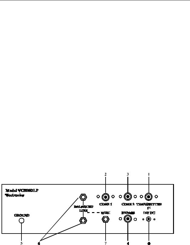
REAR PANEL CONNECTORS
1.TRANSMITTER IN
Coaxial connector for input from SWL receiver or transmitter.
2.COAX 1
Coaxial connector for output to Antenna One.
3
 Loading...