

Page 1

IMPORTANT WARRANTY INFORMATION! PLEASE READ
Return Policy on Kits When Not Purchased Directly From Vectronics: Before continuing
any further with your VEC kit check with your Dealer about their return policy. If your Dealer
allows returns, your kit must be returned before you begin construction.
Return Policy on Kits When Purchased Directly From Vectronics: Your VEC kit may be
returned to the factory in its pre-assembled condition only. The reason for this stipulation is,
once you begin i nsta lli ng a nd sol deri ng pa rt s, you essenti al ly tak e over the rol e of the devic e's
manufacturer . From this point on, neither Vect ronics nor its dea lers can reas onably be held
accountab le for the qua lity or the outcome of your work. Because of this, Vectronics cannot
accept return of any kit-in-progress or completed work as a warranty item for any reason
whatsoever. If you are a new or inexperienced kit b uilder, we urge you to read the manual
carefully a nd determine whether or not you're r eady to tak e on the job. If you wish to c hange
your mind and return your ki t, you may--b ut you must do i t before you begin c ons tr uc ti on, a nd
within ten (10) working days of the time it arrives.
Vectronics Warrants: Your kit contains each item specified in the parts list.
Missing Parts: If you determine, during your pre-construction inventory, that any part is
missing, please contact Vectronics and we'll send the missing item to you free of charge.
However, before you contact Vect ronic s, please look carefully to c onf ir m you haven't misr ea d
the marking on one of the other items provided with the kit. Also, make certain an alternative
part hasn't been substituted for the item you're missing. If a specific part is no longer
available, or if Engineering has determined that an alternative component is more suitable,
Vectronics reserves the right to make substitutions at any time. In most cases, these changes
will be clearly noted in an addendum to the manual.
Defective Parts: Today's electronic parts are physically and electrically resilient, and
defective components a re r a re. However, if you disc over a n it em duri ng your pr e- c onst r uct i on
inventory that's obviously broken or unserviceable, we'll replace it. Just return the part to
Vectronics at the address below accompanied with an explanation. Upon receipt, we'll test it.
If it's defec tive and appear s unused, we'll ship you a new one right away at no charge.
Missing or Defective Parts After You Begin Assembly: Parts and materials lost or
damaged after construction begins are not covered under the terms of this warranty. However,
most parts supplied with VEC kits are relatively inexpensive and Vectronics can replace them
for a reasonable charge. Simply contact the factory with a complete description. We'll
process your order quickly and get you back on trac k.
Factory Repair After You Begin Assembly: Kits-in progress and completed kits are
specifically excluded from coverage by the Vectronics warranty. However, as a service to
customers, tec hnicia ns ar e availa ble t o evaluate a nd repai r malf unctioni ng kits for a minimum
service fee of $18.00 (½ hour rate) plus $7.00 shipping and handling (prices subject to
change). To qualify for repair service, your kit must be fully completed, unmodified, and the
printed circuit board assembled using rosin-core solder. In the event your repair will require
more than an hour to fi x (or $36.00, subject to change), our technicians will contact you in
advance by telephone b efore p erforming t he work. Def ective unit s should b e shipp ed prep aid
to:
Vectronics
1007 HWY 25 South
Starkville, MS 39759
Page 2

When shipping, pack your kit well and include the minimum payment plus shipping and
handling charges ($25.00 total). No work can be performed without pre-payment. Also,
provide a valid UPS return address a nd a day time phone number where you may be reac hed.
Page 3

VEC-422K Owner's Manual SCA Decoder Kit
INTRODUCTION
Hidden in many standard FM broadcast signals is a host of very interesting
programming—and you can listen in for free! You’ll find commercial free
background music that the restaurants and hotels subscribe to, all news
programs, weather reports, stock quotes, digital data, ethnic programs in
different la nguages, rea ding services for the blind , and much, much more. T his
programming is carrie d by hidden sub carrier s on the FM signal , using the VEC422K SCA Decoder allows you to unlock and monitor the subcarrier
programming!
The decoder connects to your FM receiver or tuner using one simple connection!
Many receivers already have SCA output jacks. If not, we’ll give you some
simple directions for hooking up your VEC-422K to almost any FM broadcast
receiver or tuner! The heart of the VEC-422K is a special FSK decoder chip.
No alignment is needed, and construction is quick and simple thanks to the
VECTRONICS professional solder masked and screened PC board. The SCA
decoder features an on-board audio amplifier to drive headphones or a speaker,
or a line-level output to feed your HI-FI system amplifier. The VEC-422K tunes
subcarrier frequencies from 50 to 100kHz. Learn how subcarriers work, and
how they are decoded.
TOOLS AND SUPPLIES
Construction Area:
area where you can easily organize and handle small parts without losing them.
An inexpensive sheet of white poster board makes an excellent construction
surface and provides protection for the underlying table or desk. Well-diffused
overhead lighting is a plus, and a supplemental high-intensity desk lamp is
especially helpful for close-up work. Safety is always important! Be sure to use
a suitable high-temperature stand for your soldering iron, and keep the work area
free of combustible clutter.
Universal Kit-building Tools:
additional items for completion, virtually all construction projects require a work
area outfitted with the following tools and supplies:
!"
30-60 Watt Soldering Iron (temperature-controlled preferred)
!"
High-temperature Iron Holder with Moist Cleaning Sponge.
!
Rosin-core Solder (thin wire size preferred, .031”)
!"
Needle Nose Pliers or Surgical Hemostats
!
Diagonal Cutters or “Nippy Cutters”
Kit construction requires a clean, smooth, and well-lighted
Although your particular kit may require
1
Page 4

VEC-422K Owner's Manual SCA Decoder Kit
!
Solder Sucker (squeeze bulb or vacuum pump type), or Desoldering Braid
!
Bright Desk Lamp
!
Magnifying Glass
BEFORE YOU START BUILDING
Experience shows there are four common mistakes builders commonly make.
Avoid these, and your kit will probably work on the first try!
1. Installing the Wrong Part:
and a 10K resistor may look almost the same, but they may act very
differently in an electronic circuit! Same for capacitors--a device marked
102 (or .001 uF) may have very different operating characteristics from one
marked 103 (or .01uF).
2. Installing Parts Backwards:
capacitors to make sure the positive (+) lead goes in the (+) hole on the
circuit board. Transistors have a flat side or emitter tab to help you identify
the correct mounting position. ICs have a notch or dot at one end indicating
the correct direction of insertion. Diodes have a banded end indicating
correct polarity. Always double-check--especially before applying power to
the circuit!
3. Faulty Solder Connections:
bridges. Cold solder joints happen when you don't fully heat the connection-or when metallic corrosion and oxide contaminate a component lead or pad.
Solder bridges form when a trail of excess solder shorts pads or tracks
together (see Solder Tips below).
4. Omitting or Misreading a Part:
Always double-check to make sure you completed each step in an assembly
sequence.
Soldering Tips:
professional soldering. Before you install and solder each part, inspect leads or
pins for oxidation. If the metal surface is dull, sand with fine emery paper until
shiny. Also, clean the oxidation and excess solder from the soldering iron tip to
ensure maximum heat transfer. Allow the tip of your iron to contact both the
lead and pad for about one second (count "one-thousand-one") before
solder to the connection. Surfaces must become hot enough for solder to flow
smoothly. Feed solder to the opposite side of the lead from your iron tip--solder
will wick around the lead toward the tip, wetting all exposed surfaces.
Cleanliness and good heat distribution are the two secrets of
It always pays to double-check each step. A 1K
Always check the polarity of electrolytic
Inspect for cold-solder joints and solder
This is easier to do than you might think!
feeding
Desoldering Tips:
these instructions carefully! First, grasp the component with hemostats or
2
If you make a mistake and need to remove a part, follow
Page 5
VEC-422K Owner's Manual SCA Decoder Kit
needle-nose pliers. Heat the pad beneath the lead you intend to extract, and pull
gently. The lead should come out. Repeat for the other lead. Solder may fill in
behind the lead as you extract it—especially if you are working on a doublesided bo ard with plate-through hole s. Should this happen, try heating the pad
again and inserting a common pin into the hole. Solder won’t stick to the pin’s
chromium plating. When the pad cools, remove the pin and insert the correct
component. For ICs or multiple-pin parts, use desoldering braid to remove
excess solder before attempting to extract the part. Alternatively, a low-cost
vacuum-bulb or spring-loaded solder sucker may be used. Parts damaged or
severely overheated during extraction should be replaced rather than reinstalled.
Work Habits:
instructions and, in many cases, to perform new and unfamiliar tasks. To avoid
making needless mistakes, work for short periods when you’re fresh and alert.
Recreational construction projects are more informative and more fun when you
take your time. Enjoy!
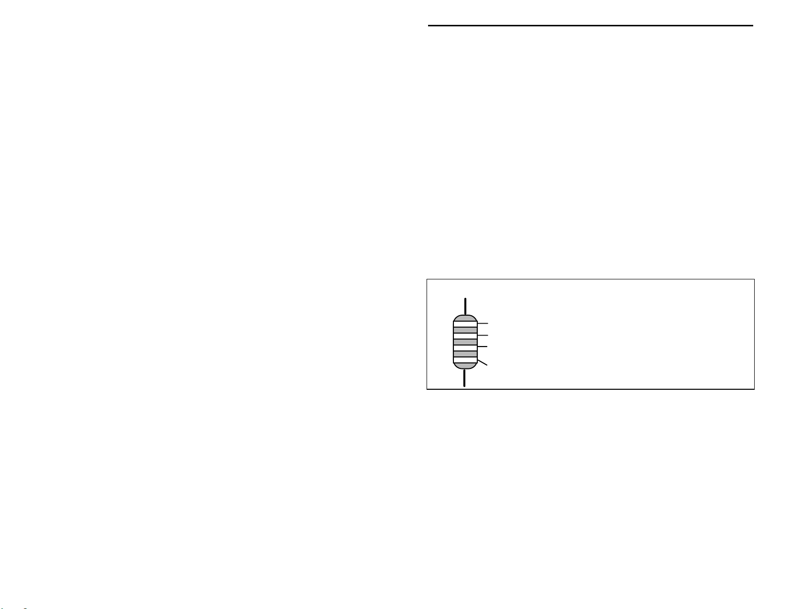
Sorting and Reading Resistors:
a color code (shown below). You don’t have to memorize this code to work with
resistors, but you do need to understand how it works:
Kit construction requires the ability to follow detailed
The electrical value of resistors is indicated by
Resistor Color Code
Black = 0 (tens)
1st Digit
2nd Digit
Multiplier
Tolerence
(gold or silver)
When you look at a resistor, check its multiplier code first. Any resistor with a
black multiplier band falls between 10 and 99 ohms in value. Brown designates
a value between 100 and 999 ohms. Red indicates a value from 1000 to 9999
ohms, which is also expressed as 1.0K to 9.9K. An orange multiplier band
designates 10K to 99K, etc. To inventory resistors, first separate them into
groups by multiplier band (make a pile of 10s, 100s, Ks, 10Ks, etc.). Next, sort
each group by specific value (1K, 2.2K, 4.7K, etc.). This procedure makes the
inventory easier, and also makes locating specific parts more convenient later on
during construction. Some builders find it especially helpful to arrange resistors
in ascending order along a strip of double-sided tape.
Brown = 1 (hundreds)
Red = 2 (K)
Orange = 3 (10K)
Yellow = 4 (100K)
Green = 5 (1Meg)
Blue = 6
Violet = 7
Gray = 8
White = 9
Silver = 10%
Gold = 5%
This VEC kit contains molded chokes which appear, at first glance, similar to
resistors in both shape and band marking. However, a closer look will enable
you to differentiate between the two—chokes are generally larger in diameter
3
Page 6
VEC-422K Owner's Manual SCA Decoder Kit
and fatter at the ends than resistors. When doing your inventory, separate out
any chokes and consult the parts list for specific color-code information.
Reading Capacitors:
value identification. Instead, the value, or a 3-number code, is printed on the
body.
Value Code
10 pF = 100
100 pF = 101
1000 pF = 102
.001 uF = 102*
.01 uF = 103
.1 uF = 104
As with resistors, it’s helpful to sort capacitors by type, and then to arrange them
in ascending order of value. Small-value capacitors are characterized in pF (or
pico-Farads), while larger values are labeled in uF (or micro-Farads). The
transition from pF to uF occurs at 1000 pF (or .001 uF)*. Today, while most
monolithic (multilayer) and disc-ceramic capacitors are marked with a threenumber code, you may still find a .1 uF capacitor marked either “104” or “.1”.
For three digit codes, the first two digits indicate a numerical value, while the
last digit indicates a multiplier (same as resistors). The value is in pF; thus a
capacitor marked “104” is 100,000 pF, or .1 uF.
Electrolytic capacitors are always marked in uF. Electrolytic capacitors are
polarized devices and must be oriented correctly during installation. If you
become confused by markings on the case, remember the uncut negative lead is
slightly shorter than the positive lead.
Unlike resistors, capacitors no longer use a color code for
Electrolytic
1 uF
1uF
|
35V
|
+
-
Multilayer
(270 pF)
271
Ceramic Discs
(.001 uF) (.1 uF)
102
104
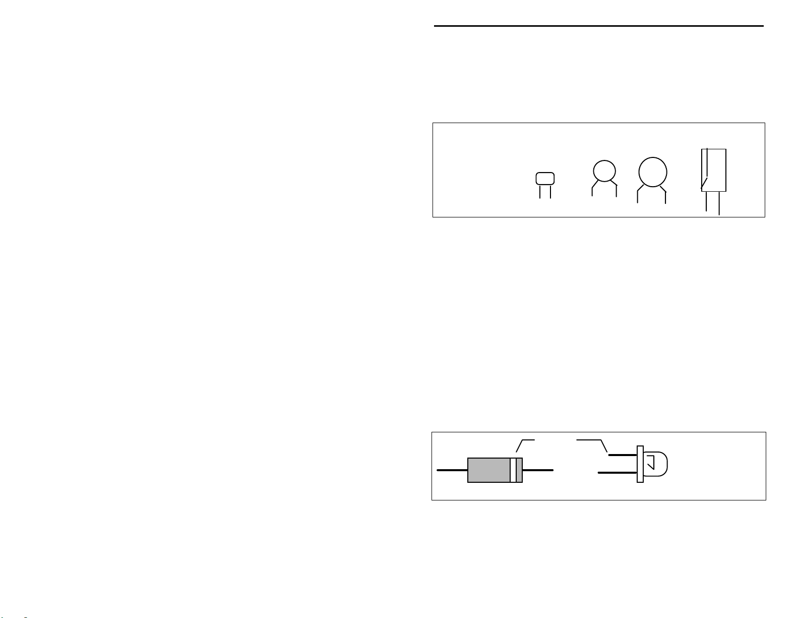
Diodes:
Always look for the banded or cathode end when installing, and follow
instructions carefully.
Transistors:
power is applied. Transistors in metal cases have a small tab near the emitter
lead to identify correct positioning. Semiconductors housed in small plastic
cases (TO-92) have an easily-identified flat side to identify mounting orientation.
Many specialized diodes and low-current voltage regulators also use this type
4
Diodes are also polarized devices that must be installed correctly.
Cathode
(shorter Lead)
Diode
If transistors are installed incorrectly, damage may result when
LED
Page 7
VEC-422K Owner's Manual SCA Decoder Kit
packaging. Larger plastic transistors and voltage regulators use a case backed
with a prominent metal tab to dissipate heat (T-220). Here orientation is
indicated by the positioning of the cooling tab.
Metal Can Device Plastic Device Tab-cooled Device
Emitter
Flat Side
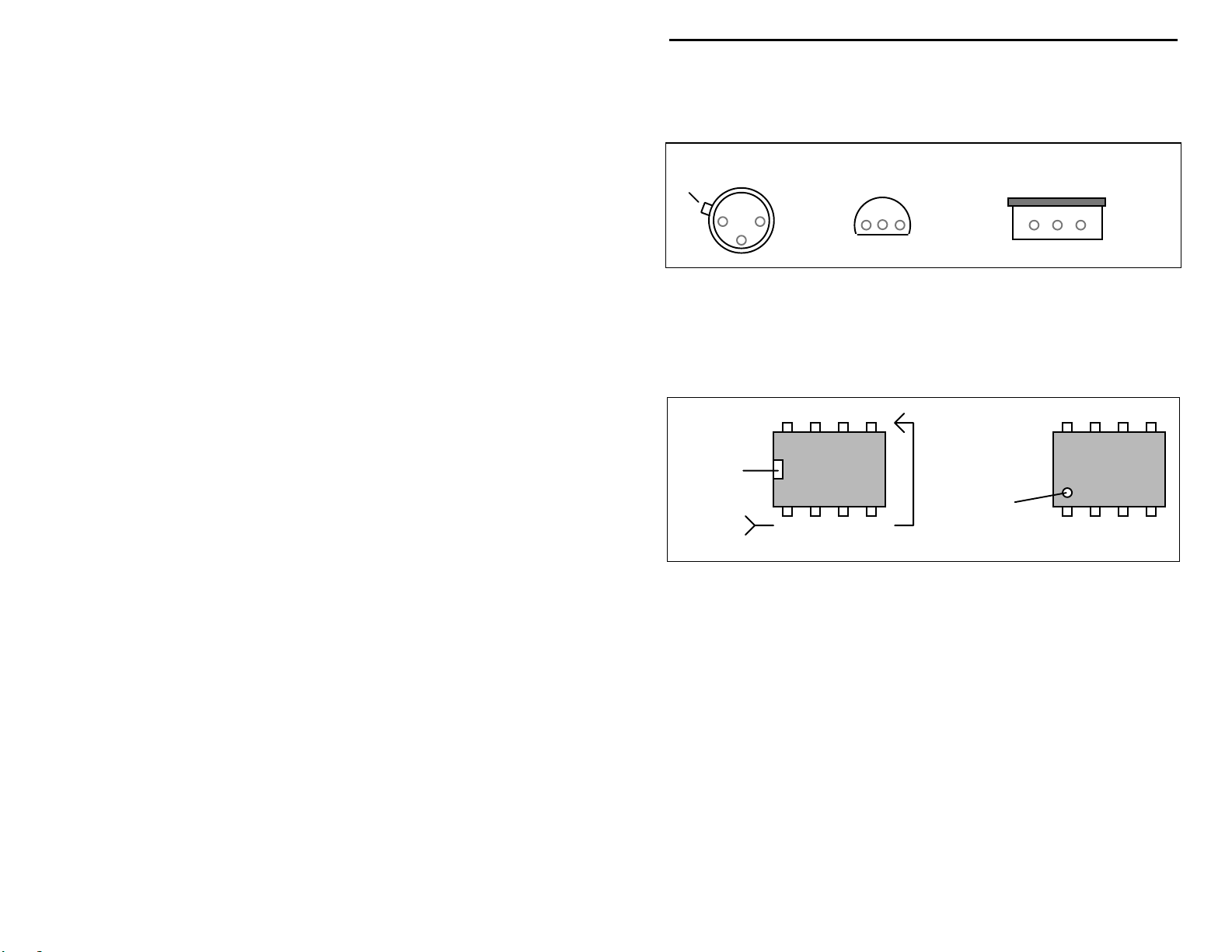
Integrated Circuits:
marking located on one end of the device. A corresponding mark is silkscreened on the PC board and printed on the kit’s parts-placement diagram. To
identify specific IC pin numbers for testing purposes, see the diagram below.
Pin numbers always start at the keyed end of the case and progress
counterclockwise around the device, as shown:
Installation
Key
Proper IC positioning is indicated by a dot or square
8 7 6 5
Installation
1 2 3 4
Pin Numbers
Metal Tab
Key
5
Page 8

VEC-422K Owner's Manual SCA Decoder Kit
PARTS LIST
Your kit should contain all of the parts listed below. Please identify and
inventory each item on the checklist before you start building. If any parts are
missing or damaged, refer to the manual’s warranty section for replacement
instructions. If you can’t positively identify an unfamiliar item on the basis of
the information given, set it aside until all other items are checked off. You may
then be able to identify it by process of elimination. Finally, your kit will go
together more smoothly if parts are organized by type and arranged by value
ahead of time. Use this inventory as an opportunity to sort and arrange parts so
you can identify and find them quickly.
Resistors:
Note: The fourth color band (gold) denotes tolerance, only the three bands
determining resistance value are listed.
#
Qty Part Description Designation
!
1 15-ohm ¼-watt resistor (brown-green-black) R15
!
3 510-ohm ¼-watt resistor (green-brown-brown) R1,R3,R5
!
3 4.7K-ohm ¼-watt resistor (yellow-violet-red) R6,R10,R13
!
1 10K-ohm ¼-watt resistor (brown-black-orange) R4
!
1 18K-ohm ¼-watt resistor (brown-gray-orange) R8
!
3 24K-ohm ¼-watt resistor (red-yellow-orange) R11,R12,R14
!
3 100K-ohm ¼-watt resistor (brown-black-yellow) R2,R7,R9
!
1 10K-ohm variable resistor R17
!
1 50K-ohm variable resistor R16
Capacitors:
#
Qty Part Description Designation
!
2 120-pF monolithic (121) C2,C9
!
1 470-pF monolithic (471) C1
!
3 .001-uF monolithic (102) C6,C10,C12
!
1 .0022-uF monolithic (222) C11
!
1 .0047-uF monolithic (472) C4
!
2 .01-uF monolithic (103 or .01) C3,C5
!
3 .1-uF monolithic (104 or .1) C7,C8,C13
!
3 1-uF electrolytic C16,C17,C18
!
2 470-uF electrolytic C14,C15
6
Page 9

VEC-422K Owner's Manual SCA Decoder Kit
Semiconductors:
#
Qty Part Description Designation
!
4 2N3904 plastic transistor Q1,Q2,Q3,Q4
!
1 LM386 linear audio IC, 8 pin U2
!
1 XR2211 FSK demodulator IC, 14 pin U1
Inductors:
#
Qty Part Description Designation
!
2 330-uH molded choke (orange-orange-brown) L1,L2
Miscellaneous:
#
Qty Part Description Designation
!
1 DPDT push-action switch SW1
!
2 RCA phono jacks, PC board mount J1,J2
!
1 3.5mm stereo jack, PC board mount J3
!
1 8-pin DIP IC socket U2
!
1 14-pin DIP IC socket U1
!
1 9-volt transistor battery clip
!
1 4” nylon wire tie wrap
!
1 VEC-442 PC board
!
1 3-inch length insulated hookup wire
7
Page 10

Page 11

VEC-422K Owner's Manual SCA Decoder Kit
STEP-BY-STEP ASSEMBLY
Before assembling your kit, please take time to read and understand the VEC kit
warranty printed on t he inside co ver of this manual. Read thro ugh the assembly
instructions to make sure the kit does not exceed your skill level. Once
construction is started, the kit is non-returnable. Finally, if you haven’t already
done so, please verify that all parts listed in the inventory are included. If
anything is missing or broken, refer to the warranty instructions for replacing
missing or damaged parts.
First, a few notes and comments to help you along. Part designators for
components such as R1, C3, etc., appear on the silk-screened legend on the
component-mounting side of the printed circuit board. These correspond to the
drawing shown in the Parts Placement Diagram found in this manual. The parts
are inserted on the silk-screen side of the board. All capacitors should be
installed with their bodies as close to the PC board as possible; this is very
important in RF circuits.
If you have last-minute questions concerning what tools or materials are needed
to assembly this kit, please refer back to the section entitled “Before You Start
Building”.
“Install”
and insert the part into its mounting holes on the PC board. T his includes prebending or straightening leads as needed so force is not required to seat the part.
Once a component is mounted, bend each lead over to hold it in place. Make
sure trimmed leads don’t touch other pads and tracks, or a short circuit may
result:
“Solder”
in place, and to inspect both (or all) solder connections for flaws or solder
bridges. If no soldering problems are noted, nip off the excess protruding leads
with a sharp pair of side cutters.
Notice the directions use two sets of check boxes. Check one when a step is
complete and use the other for double-checking your work before operation.
When you are directed to install a part, this means to locate, identify,
Good
When you are directed to solder, this means to solder the part’s leads
Not Good
9
Page 12

VEC-422K Owner's Manual SCA Decoder Kit
Resistor Installation:
Begin assembly by installing the ¼-watt fixed resistors. Because these are all 5percent tolerance ending with a fourth gold color band, you need only read the
first three bands of the color code during the following steps. All resistor leads
should be for med as shown below. Install and solder resistor s at the following
locations:
.4"
NOTE: the fourth resistor color band is for tolerance, and is not called out in
the following steps.
! !
1. Locate the 15-ohm resistor (brown-green-black). Install and solder at
location R15.
Locate the three 510-ohm resistors (green-brown-brown). Install and solder at
the following locations:
! !
2. R1 510-ohm resistor (green-brown-brown)
! !
3. R3 510-ohm resistor (green-brown-brown)
! !
4. R5 510-ohm resistor (green-brown-brown)
Locate the three 4.7K-ohm resistors (yellow-violet-red). Install and solder at the
following locations:
! !
5. R6 4.7K-ohm resistor (yellow-violet-red)
! !
6. R10 4.7K-ohm resistor (yellow-violet-red)
! !
7. R13 4.7K-ohm resistor (yellow-violet-red)
! !
8. Locate the 10K-ohm resistor (brown-black-orange) . Install and solder
at location R4.
! !
9. Locate the 18K-ohm resistor (brown-gray-orange). Install and solder
at location R8.
Locate the three 24K-ohm resistors (red-yellow-orange). Install and solder at the
following locations:
! !
10. R11 24K-ohm resistor (red-yellow-orange)
! !
11."R12 24K-ohm resistor (red-yellow-orange)
! !
12."R14 24K-ohm resistor (red-yellow-orange)
10
Page 13

VEC-422K Owner's Manual SCA Decoder Kit
Locate the three 100K-ohm resistors (brown-black-yellow). Install and solder at
the following locations:
! !
13."R2 100K-ohm resistor (brown-black-yellow)
! !
14. R7 100K-ohm resistor (brown-black-yellow)
! !
15. R9 100K-ohm resistor (brown-black-yellow)
Non-polarized capacitor installation:
Important Note:
characteristics, but the lead welds
installation or removal. For this reason,
into the PC board. If the spacing isn’t right, pre-form the leads to the correct
spacing before inserting into the board.
Monolithic capacitors have superior radio-frequency operating
fail if the device is over-stressed during
may
never use force to seat a monolithic cap
Incorrect
Ooops!
Correct
Locate the two 120-pF monolithic capacitors (121). Install and solder at the
following locations:
! !
1."C2 120-pF monolithic capacitor (121)
! !
2."C9 120-pF monolithic capacitor (121)
! !
3."Locate the 470-pF monolithic capacitor (471), install and solder at C1.
Locate the three .001-uF monolithic capacitors (102). Install and solder at the
following locations:
! !
4."C6 .001-uF monolithic capacitor (102)
! !
5."C10 .001-uF monolithic capacitor (102)
! !
6."C12 .001-uF monolithic capacitor (102)
! !
7."Locate the .0022-uF monolithic capacitor (222). Install and solder at
C11.
! !
8."Locate the .0047-uF monolithic capacitor (472). Install and solder at
C4.
Locate the two .01-uF monolithic capacitors (103 or .01). Install and solder at
the following locations:
! !
9."C3 .01-uF monolithic capacitor (103 or .01)
11
Page 14

VEC-422K Owner's Manual SCA Decoder Kit
! !
10."C5 .01-uF monolithic capacitor (103 or .01)
Locate the three .1-uF monolithic capacitors (104 or .1). Install and solder at the
following locations:
! !
11."C7 .1-uF monolithic capacitor (104 or .1)
! !
12."C8 .1-uF monolithic capacitor (104 or .1)
! !
13."C13 .1-uF monolithic capacitor (104 or .1)
Molded choke and inductor installation:
Note: only the first three color bands for the molded choke color codes are
specified in the following directions. The fourth band is for tolerance and may
be disregarded.
Locate the two 330-uH molded chokes (orange-orange-brown). Install and
solder at the following locations:
! !
1."L1 330-uH molded choke (orange-orange-brown)
! !
2."L2 330-uH molded choke (orange-orange-brown)
Polarized capacitor installation:
Electrolytic capacitors are polarized devices, and must be inserted with respect
to polarity. The style used in the VEC direct conversion receivers have radial
leads; both leads exit from one end of the device body. Each capacitor’s plus (+)
mounting holes are noted both on the circuit board and parts placement diagram.
If the markings on the capacitor body are unclear, the plus (+) lead is the longer
of the two.
Locate the three 1-uF electrolytic capacitors. Install and solder at the following
locations:
! !
1."C16 1-uF electrolytic capacitor. Observe polarity!
! !
2."C17 1-uF electrolytic capacitor. Observe polarity!
! !
3."C18 1-uF electrolytic capacitor. Observe polarity!
Locate the two 470-uF electrolytic capacitors. Install and solder at the following
locations:
! !
4."C14 470-uF electrolytic. Observe polarity!
! !
5."C15 470-uF electrolytic. Observe polarity!
12
Page 15

VEC-422K Owner's Manual SCA Decoder Kit
Semiconductors:
2N3904
Note: The 2N3904 transistor body has a flat and rounded side. The device body
outline must correspond to the silk-screened component outline on the PC
board.
Locate the four 2N3904 plastic transistors. Install and solder at the following
locations:
! !
1."Q1 2N3904 transistor, observe alignment!
! !
2."Q2 2N3904 transistor, observe alignment!
! !
3."Q3 2N3904 transistor, observe alignment!
! !
4."Q4 2N3904 transistor, observe alignment!
Locate the 14-pin IC socket. Note that the socket is keyed—a small notch shows
pin 1 alignment.
14 13 12 11 10 9 8
Installation
Key
1 2 3 4 5 6 7
Pin Numbers
! !
5. Install and solder the 14-pin IC socket at location U1. Observe that
the key aligns with the legend outline on the PC board.
Top view of socket
13
Page 16

VEC-422K Owner's Manual SCA Decoder Kit
Installation
Key
The IC body has a small notch, or key, molded at one end, indicating pins 1 and
14. A small dimple-like body-molding is often found adjacent to pin 1. Some
IC packages may include both key indicators.
Locate the XR2211 14-pin IC.
! !
6."Align the body of the XR2211 to correspond with the key of socket
U1. Loosely insert the pins of the XR2211 into socket U1. All 14
pins should fit freely into the socket openings. If not, straighten the IC
pins until they do. Using firm and steady pressure, fully seat the IC
into the socket.
! !
7."Locate the 8-pin IC socket. Install and solder at location U2. Observe
key alignment!
! !
8."Locate the LM386 audio IC. Align the body of the LM386 to
correspond with the key of socket U2. Loosely insert the pins of the
LM386 into socket U1. All 8 pins should fit freely into the socket
openings. If not, straighten the IC pins until they do. Using firm and
steady pressure, fully seat the IC into the socket.
XR2211
1
Final steps:
! !
1."Locate the push-action DPDT power switch. Install at SW1. The
push shaft should extend over the edge of the board. Be sure the
switch is fully seated and level before soldering. Solder.
Locate the two RCA jacks. Install and solder at the following locations (note:
ensure the leads are fully inserted). Bend the pins over so they contact the
copper foil surface. This will improve the mechanical strength of the solder joint.
! !
2."J1 RCA jack.
! !
3."J2 RCA jack.
! !
4."Locate the 3.5mm jack. Install at J3. Be sure the switch is fully seated
and level before soldering. Solder.
14
Page 17

VEC-422K Owner's Manual SCA Decoder Kit
The front-panel controls are mounted next. Before installing these parts, inspect
the potentiometer supplied with your kit. If the pins are located on the front side
of the pot, use the front set of mounting holes on the PC board for installation. If
the pins are on the rear, use the rear set of mounting holes (see below). If
necessary, use side cutters to remove the key tab from the side of each pot prior
to installation.
Rear pins use rear holes.
Front pins use front holes.
Nip off tab.
Nip off tab.
Note: The resistance value is stamped on the front body for the rear-pin style
potentiometers.
! !
5."Locate the 10K-ohm variable resistor. Install and solder at location
R17 (volume control).
! !
6."Locate the 50K-ohm variable resistor. Install and solder at location
R16 (tuning cont rol).
Locate the battery clip.
! !
7."Solder the red lead (positive) to the (+) location on the PC board.
! !
8."Solder the black lead (negative) to the (-) location on the PC board.
! !
9."Find the 4” nylon wire tie wrap. Secure the battery leads to the stress
relief hole on the PC board using the nylon tie wrap. Trim excess tie
length.
Tie wrap
- black
+ red
SW1
15
Page 18

VEC-422K Owner's Manual SCA Decoder Kit
Important Note:
bottom, or solder side, of the PC board. It is very important that the jumper wire
be connected precisely as directed!
The following steps will involve installing a jumper wire on the
Locate the 3 ” length of hookup wire.
Locate pin 6 of the 8-pin socket for the LM386 chip at location U2.
! !
10."Trim the exposed wire from one end the insulated jumper wire to
about 1/16”. Solder this end of the insulated jumper wire to pin 6.
Be
very careful not to bridge adjacent IC socket pins!
! !
11."Solder the other end of the insulated jumper to the rear set of pins
(furthest from the shaft) for power SW1 on the solder side of the
board.
16
Page 19

VEC-422K Owner's Manual SCA Decoder Kit
The assembly of the VEC-422K SCA decoder is completed.
TESTING AND ALIGNMENT
Testing:
Here are few simple voltage tests to check out the adapter.
Note: Nine volt battery attached and SW1 on (shaft latched inward).
U2 LM386 9 volts at pin 6. About 4.5 volts at pin 5.
U1 XR2211 9 volts at pin 8.
The following tests need only be performed if you have access to the required
test equipment. The advanced test proves that the unit is working flawlessly.
Advanced test:
sinewave into jack J1. Monitor pin 11 of the XR2211 with a scope (.1-volt per
division, AC coupled, 10uS sweep per division). Observe the scope signal while
slowly rotating tuning control R16. The scope pattern should change from a
jittery pattern to a stable tria ngular waveform (about .3-volts P-P) when lock is
achieved.
Some function generators will accept a VCG input (such as the Wavetek model
III). Apply audio to the VCG input to FM modulate the 67-kHz signal. When
tuned for lock, the modulating signal should be audible in the monitor speaker
(jack J4 output). Adjust the volume control for best level. Vary the signal
generator output from 50kHz to 100kHz in several steps, and tune for lock at
each frequency.
Alignment:
when assembly and testing are completed!
The final test is proving the SCA adapter works with your receiver.
Using a function or aud io ge nerat or , inje ct a 60-mV P-P 67-kHz
There is no alignment required for this project. It is ready to enjoy
17
Page 20

VEC-422K Owner's Manual SCA Decoder Kit
OPERATING INSTRUCTIONS
Tuning in SCA signals:
SCA programming, you will have to explore each station to find if it has hidden
SCA programming. Tune into the FM station; and then carefully tune R16 while
listening for SCA signals. If a SCA subcarrie r is present, and is strong enough,
you should hear the SCA programming when the Phased Locked Loop (PLL)
locks onto the subcarrier signal. Volume control R17 is used when an external
speaker or headphones are attached to the VEC-422K to set the audio to a
comfortable listening level. Don’t ignore the Public Broadcasting and college
FM stations at the lower end of the FM dial, they are public service oriented and
often carry community oriented SCA programs.
What is an SCA signal?
programs are auxiliary revenue-producing services provided by many FM
stations. The use of the subcarriers is “sold”, just as commercial airtime is sold
for commercials. SCA subcarriers are located at 67kHz and 92kHz from the
main carrier, and transmit with a 7.5kHz deviation maximum. It is not a HI-FI
service, as its audio bandwidth is limited to about 5kHz. In theory, each FM
station can carry several subcarrier services. ARI, or Automobile Road Services,
normally operates on a 57kHz subcarrier. This is a limited bandwidth channel,
and requires special equipment for decoding the information. ARI provides
constant road advisory updates to motorists who subscribe to the service. Each
subcarrier reduces the main channel signal strength by about 1dB. Thus, few
stations are willing to lose 2dB of signal strength to carry two subcarrier (SCA)
services. Most SCA services will be found using the 67kHz subcarrier. Urban
areas with high population densities will generally offer more SCA services than
in a rural area. The original 41kHz SCA subcarrier is seldom used, due to its
incompatibility with the 38kHz stereo subcarrier.
Unless you know which FM broadcaste rs are carrying
SCA (Subsidiary Communications Authorization)
The SCA signal rep resent s abo ut 10 % of the t otal FM signal, thus it is unusual ly
weak and prone to fading or being noisy. The SCA subcarrier can also suffer
from “splatter” from the main audio channel, resulting in occasional noise bursts
on the SCA signal. This means even though the main FM signal sound s good,
the SCA subcarrier may still be too weak for the VEC-422K to decode properly.
Use a good outdoor antenna to capture the most signal level.
What you can hear:
Providing commercial-free b ackground music fo r restaurant s and waiting rooms
is just one of many uses. There are also SCA services for physicians giving the
latest medical news, reading and news services for the visually handicapped, and
second-language programming for ethnic populations.
Power requireme nts:
Alkaline batteries are more expensive initially, but are more economical over the
18
SCA programming is used for a variety of purposes.
Power is supplied via an internal 9-volt transistor battery.
Page 21

VEC-422K Owner's Manual SCA Decoder Kit
long run. Remember to turn the SCA Adapter off when not in use to conserve
battery power.
Interconnecting cables:
the VEC-422K using shielded audio cable (jack J1). Radio Shack and most
department stores carry good selections of A/V hookup cables. The FM receiver
or tuner should be equipped with an RCA phono jack for the SCA output. The
line-level output is also an RCA phono jack (J2). Shielded audio cable should
be used for interconnecting the line-level output to an external audio amplifier.
Audio:
directly (RCA phono jack J2). The VEC-422K also includes an on-board audio
amplifier to drive a speaker (4 to 32 ohms, 50 mW max.) or headphones at jack
J3. The headphones should be equipped with a 3.5mm monaural jack. Stereo
phones with a 3.5mm jack may be used, but only one earpiece will be active.
Connecting to the receiver:
with an SCA adapter jack. If your receiver has a SCA jack, you need only
provide the necessary shielded cable from the receiver SCA jack to the SCA
input (jack J1) on the VEC-422K. Some older FM receivers featured a “MPX”
output jack—this is also an ideal point for connecting to an external SCA
Decoder. The MPX signal is taken from the detector, before the SCA filtering
and de-emphasis circuits. Newer receivers may have a jack for “four-channel
decoders” or “quadrasound decoders”; again, these are also taken directly from
the FM detector and can be used to supply SCA subcarrier signals to the VEC422K. You might notice that the VEC-422K reduces the level of FM audio on
some receivers when it is attached; disconnect the VEC-422K when not in use if
this is a problem.
Receiver modifications:
you will have to provide one. FM receivers can use one of several types of FM
detector circuits. The majority use either a Ratio Detector, Discriminator, or
Quadrature Detector to recover audio from the FM carrier. Unless you are an
experienced technician, you may wish to have the jack installed by a service
shop. There is usually room to add an RCA jack on the rear apron of most FM
receivers or tuners. The following schematics are representative of typical FM
detector circuits, and gives an idea of the proper take-off point for the SCA
subcarrier signal. The ratio detector circuit is very similar to the discriminator
circuit, which is not shown.
The SCA Adapter has a line-level audio output to feed hi-fi amplifiers
The demodulated SCA signal should be connected to
Some FM receivers or FM tuners come equipped
If your receiver does not have an SCA adapter jack,
19
Page 22

VEC-422K Owner's Manual SCA Decoder Kit
WARNING: Many inexpensive table top stereos or tube-
type FM receivers may use a ‘‘hot chassis’’.
This is commonly found in transformerless
sets that are designed to operate from AC/DC
voltages. VECTRONICS advises against using
these receivers with the VEC-422K to avoid
shock hazards!
FCC regulations:
Communications Act of 1934, Section 605 of the FCC rules, and various other
State and Federal laws apply to the interception of private radio transmissions.
Many SCA transmissions are subscriber based, that means a fee is charged for
commercial use of the program material. An example would be background
20
The following is what you may and may not do legally. The
Page 23

VEC-422K Owner's Manual SCA Decoder Kit
music for restaurants or hotels. You may monitor these programs, providing
they are for your own or immediate family’s enjoyment. Using them in a place
of business to provide background music for customers without being a
subscriber is theft of service. Stock reports are carried on some SCA systems.
Again, monitoring the programs for your own enjoyment is legal, using the
information to make investments is a form of personal gain and is illegal. (In
most instances stock services require special decoding equipment.) The
Communications Act of 1934 also strictly prohibits divulging the contents of any
intercepted private radio communications. The laws governing the interception
and monitoring of private radio communications are very dynamic and ever
changing. Protect your rights as a radio hobbyist by using the VEC-422K in a
responsible and legal manner.
IN CASE OF DIFFICULTY
Only high-quality components and proven circuit designs are used in Vectronics
kits. In very rare instances is a defective component the source of a problem.
Replacement of defective parts is covered in the
percent of the kits returned for factory repair are due to soldering problems or
parts in the wrong locations. We advise repeating the assembly instructions
step-by-step, looking for mistakes or soldering problems. Be especially wary of
electrolytic capacitors and semiconductors. Kit builders often miss obvious
mistakes. What is needed is a “fresh” set of eyes. Enlist a friend to go over your
work.
Warranty
section. Nine ty-five
Always check the obvious! Is the battery dead? Is the power switch on?
The majority of reception problems can be traced to a few major causes. The
FM signal must be strong—if the signal is weak the SCA subcarrier will also be
weak, and the XR2211 decoder may not be able to lock to it. The SCA
subcarrier modulation is typically 10% of the total FM deviation. The SCA
subcarrier must be taken directly from the FM detector stage, before any RC deemphasis circuits or filters limit bandwidth and reduce the SCA signal. Not all
FM stations broadcast SCA signals. Nor, are the SCA subcarriers always
present when there is no programming activity. The advanced test procedure
shown earlier may be used to prove whether there is a problem in the unit, or
with the receiver hookup.
THEORY OF OPERATION
Recovered audio from the FM detector is sent directly to the SCA Adapter input.
The signal pick-off point must be directly from the detector output before any
de-emphasis takes place.
21
Page 24

VEC-422K Owner's Manual SCA Decoder Kit
The XR2211 is a Phase Locked Loop (PLL). Tuning control R16 varies the
VCO (Voltage Controlled Oscillator) section of the XR2211 over the range of
frequencies used by the SCA services. When a subcarrier is detected, the VCO
will lock to the subcarrier frequency once the tuning control is in range. Lock is
achieved by the Phase Detector generating an error correcting voltage (steering
voltage) and feeding it back to the VCO to keep it locked on frequency.
The subcarriers are FM modulated, that is the frequency of the subcarrier varies
according to the program material. The phase detector sees these frequency
variations, and continually adjusts the steering voltage to keep the VCO in lock.
These voltage variations faithfully mimic the program material, and by simply
coupling an audio amplifier into the tuning voltage line, the program material
may be recovered and monitored.
SCA
signal s
P.D.
Audio
amplifier
VCO
Error corre cting
voltage.
Specifications:
SCA subcarrier range ......................50 to 100kHz
Power requirements.........................9-volt transistor battery, alkaline preferred
Audio output J2...............................line level output
Audio output J3...............................4 to 32 ohms, 50mW max.
PC Board.........................................4.000" x 4.700"
22
Page 25

Page 26

VEC-422K Owner's Manual SCA Decoder Kit
ENCLOSURE
Vectronics has designed a matching enclosure just for your VEC-422K SCA
Decoder Kit. The matching enclosure is an all metal box which includes knobs,
hardware, decals, and rubber feet.
To install your decoder in the VEC-422KC matching enclosure follow these instructions
(read all instructions before beginning ... take your time)
1.
Find the fron t panel decal and rear p anel decal; separate usin g scissors. Be sure to
leave excess decal material around the edges. Put the rear panel decal on first. This
is done by:
using a piece of cloth and alcohol.
adhesive.
Gently rub the alignment circles with your finger--if the circles are centered in the
enclosure holes (also check the corner alignment marks) secure the decal by rubbing
and removing all air bubbles.
decal accordingly then secu re.
away the unused edges (cut from the adhesive side) and cut out the component holes
(cut from the description side).
2.
Next, install the two L-brackets on the chassis using two of the 3/16" screws. The
longer side of the L-bracket must be connected to the chassis using the two holes
centered on each edge o f the enclosure. Refer to the d iagram on the next page for
location and orientation.
3.
Install the two 1/2" mounting screws next. Insert the screws, from the bottom,
through the four holes relatively close to each corner of the chassis.
4.
Place the two 3/16" round spacers on the mounting screws.
5.
Now insert the PC board. This must be done by:
from R16 and R17.
enter their respective holes.
mounting screws align with the mounting holes in the PC board before pushing.
6.
Use the two hex nuts to secure the PC board. Be certain all appropriate components
are centered with the enclosure holes before tightening. Put the washers and nuts-removed from R16 and R17--back on and tighten.
7.
Find the knobs and switch cap. Align the switch cap with SW1 and push it on. If it
is difficult to push on, then rotate it 90° and try again. Now put the knobs on R16
and R17. You may need to loosen the set screw. Align appropriately then tighten
the set screw.
8.
Locate the piece of double-sided tape. This is to be used for holding the 9-volt
battery clip in place. Locate a place on the underside of the top cover where the
battery will not interfere with any components. Peel off the backing of the tape and
stick it to the chosen location, then install the battery clip.
9.
The top should be installed next. Use the two remaining 3/16" screws for securing
the top to the L-brackets. Make sure the L-brackets are aligned properly.
10.
Finally, place the four rubber feet on the bottom of the enclosure at the corners.
a.)
Remove all debris and oil from the chassis. This should be done
c.)
Place the decal on the rear panel without securing it completely.
b.)
Insert the front of the PC board at an angle, so the controls
Enclosure Model Number: VEC-422KC.
:
b.)
Remove the crack and peel to exp ose the
e.)
If the alignment circles are n ot cent ered, adj ust th e
f.)
Use a penknife, or small Exacto
g.)
Repeat this procedure for the front panel.
a.)
Remove the nuts and washers
c.)
Push down on the rear of the board. Make sure the
TM
knife, to cut
d.)
24
Page 27

 Loading...