

Page 1

IMPORTANT WARRANTY INFORMATION! PLEASE READ
Return Policy on Kits When Not Purchased Directly From Vectronics: Before continuing
any further with your VEC kit check with your Dealer about their return policy. If your Dealer
allows returns, your kit must be returned before you begin construction.
Return Policy on Kits When Purchased Directly From Vectronics: Your VEC kit may be
returned to the factory in its pre-assembled condition only. The reason for this stipulation is,
once you begin i nsta lli ng a nd sol deri ng pa rt s, you essenti al ly tak e over the rol e of the devic e's
manufacturer . From this point on, neither Vect ronics nor its dea lers can reas onably be held
accountab le for the qua lity or the outcome of your work. Because of this, Vectronics cannot
accept return of any kit-in-progress or completed work as a warranty item for any reason
whatsoever. If you are a new or inexperienced kit b uilder, we urge you to read the manual
carefully a nd determine whether or not you're r eady to tak e on the job. If you wish to c hange
your mind and return your ki t, you may--b ut you must do i t before you begin c ons tr uc ti on, a nd
within ten (10) working days of the time it arrives.
Vectronics Warrants: Your kit contains each item specified in the parts list.
Missing Parts: If you determine, during your pre-construction inventory, that any part is
missing, please contact Vectronics and we'll send the missing item to you free of charge.
However, before you contact Vect ronic s, please look carefully to c onf ir m you haven't misr ea d
the marking on one of the other items provided with the kit. Also, make certain an alternative
part hasn't been substituted for the item you're missing. If a specific part is no longer
available, or if Engineering has determined that an alternative component is more suitable,
Vectronics reserves the right to make substitutions at any time. In most cases, these changes
will be clearly noted in an addendum to the manual.
Defective Parts: Today's electronic parts are physically and electrically resilient, and
defective components a re r a re. However, if you disc over a n it em duri ng your pr e- c onst r uct i on
inventory that's obviously broken or unserviceable, we'll replace it. Just return the part to
Vectronics at the address below accompanied with an explanation. Upon receipt, we'll test it.
If it's defec tive and appear s unused, we'll ship you a new one right away at no charge.
Missing or Defective Parts After You Begin Assembly: Parts and materials lost or
damaged after construction begins are not covered under the terms of this warranty. However,
most parts supplied with VEC kits are relatively inexpensive and Vectronics can replace them
for a reasonable charge. Simply contact the factory with a complete description. We'll
process your order quickly and get you back on trac k.
Factory Repair After You Begin Assembly: Kits-in progress and completed kits are
specifically excluded from coverage by the Vectronics warranty. However, as a service to
customers, tec hnicia ns ar e availa ble t o evaluate a nd repai r malf unctioni ng kits for a minimum
service fee of $18.00 (½ hour rate) plus $7.00 shipping and handling (prices subject to
change). To qualify for repair service, your kit must be fully completed, unmodified, and the
printed circuit board assembled using rosin-core solder. In the event your repair will require
more than an hour to fi x (or $36.00, subject to change), our technicians will contact you in
advance by telephone b efore p erforming t he work. Def ective unit s should b e shipp ed prep aid
to:
Vectronics
1007 HWY 25 South
Starkville, MS 39759
Page 2

When shipping, pack your kit well and include the minimum payment plus shipping and
handling charges ($25.00 total). No work can be performed without pre-payment. Also,
provide a valid UPS return address a nd a day time phone number where you may be reac hed.
Page 3

VEC-412K Owner's Manual Rapid Battery Charger/Conditioner Kit
INTRODUCTION
Quickly and safely charge all types of NiCad or NiMH batteries; including cell
phones, camcorders, lap-top computers, hand-held radios—many in less than a
hour! Vectronics’ exclusive
RapidBattery
batteries are fully charged and its top-off feature keeps batteries at full-charge,
without overcharging. Simple wall-chargers can fry expensive battery packs if
used for weeks at a time. You set how many cells are to be charged, what charge
rate to use and for how long, and the discharge rate. The smart integrated circuit
chip then takes control—it senses the correct points for discharge and fullcharge. After a full charge, the charger automatically keeps the battery at peak
capacity with a periodic top-off charge.
NiCads can develop a memory effect making your batteries appear to be nearly
dead or to have a shortened life. Vectronics’s discharge-before-charge feature
can recondition NiCads to near new operation by first fully discharging the cells,
and then fully recharging the cells. After a few cycles, the memory effect will be
reversed, making your expensive battery packs work like new!
TM
technology determines when your
Extend your battery’s useful life. Save valuable time with the Vectronics
RapidBattery
TM
charger kit. No more waiting ho urs for poky trickl e chargers,
and an end to wasting your hard earned dough on new battery pa cks.
TOOLS AND SUPPLIES
Construction Area:
area where you can easily organize and handle small parts without losing them.
An inexpensive sheet of white poster board makes an excellent construction
surface, while providing protection for the underlying table or desk. Welldiffused overhead lighting is a plus, and a supplemental high-intensity desk lamp
will prove especially helpful for close-up work. Safety is an important
consideration. Be sure to use a suitable high-temperature stand for your
soldering iron, and keep the work area free of combustible clutter.
Universal Kit-building Tools:
additional items to complete, virtually all construction projects require a work
area outfitted with the following tools and supplies:
!
30 to 60 Watt Soldering Iron
!
High-temperature Iron Holder with Moist Cleaning Sponge
!
Rosin-core Solder (thin wire-size preferred)
!
Needle Nose Pliers or Surgical Hemostats
!
Diagonal Cutters or "Nippy Cutters"
Kit construction requires a clean, smooth, and well-lighted
Although your particular kit may require
1
Page 4

VEC-412K Owner's Manual Rapid Battery Charger/Conditioner Kit
!
Solder Sucker, Vacuum Pump, or Desoldering Braid
!
Bright Desk Lamp
!
Magnifying Glass
!
Phillips screw driver
BEFORE YOU START BUILDING
Experience shows there are four common mistakes builders make. Avoid these,
and your kit will probably work on the first try! Here's what they are:
1. Installing the Wrong Part:
and a 10K resistor may look almost the same, but they may act very
differently in an electronic circuit! Same for capacitors--a device marked
102 (or .001 uF) may have very different operating characteristics from one
marked 103 (or .01uF).
2. Installing Parts Backwards:
capacitors to make sure the positive (+) lead goes in the (+) hole on the
circuit board. Transistors have a flat side or emitter tab to help you identify
the correct mounting position. ICs have a notch or dot at one end indicating
the correct direction of insertion. Diodes have a banded end indicating
correct polarity. Always double-check--especially before applying power to
the circuit!
3. Faulty Solder Connections:
bridges. Cold solder joints happen when you don't fully heat the connection-or when metallic corrosion and oxide contaminate a component lead or pad.
Solder bridges form when a trail of excess solder shorts pads or tracks
together (see Solder Tips below).
4. Omitting or Misreading a Part:
Always double-check to make sure you completed each step in an assembly
sequence.
Soldering Tips:
professional soldering. Before you install and solder each part, inspect leads or
pins for oxidation. If the metal surface is dull, sand with fine emery paper until
shiny. Also, clean the oxidation and excess solder from the soldering iron tip to
ensure maximum heat transfer. Allow the tip of your iron to contact both the
lead and pad for about one second (count "one-thousand-one") before feeding
solder to the connection. Surfaces must become hot enough for solder to flow
smoothly. Feed solder to the opposite side of the lead from your iron tip--solder
will wick around the lead toward the tip, wetting all exposed surfaces. Apply
Cleanliness and good heat distribution are the two secrets of
It always pays to double-check each step. A 1K
Always check the polarity of electrolytic
Inspect for cold solder joints and solder
This is easier to do than you might think!
2
Page 5
VEC-412K Owner's Manual Rapid Battery Charger/Conditioner Kit
solder sparingly, and do not touch solder directly to the hot iron tip to promote
rapid melting.
Desoldering Tips:
these instructions carefully! First, grasp the component with a pair of hemostats
or needle-nose pliers. Heat the pad beneath the lead you intend to extract, and
pull gently. The lead should come out. Repeat for the other lead. Solder may
fill in behind the lead as you extract it--especially if you are working on a
double-sided b o ar d with plat e-thr o ugh hol es. Sho uld this ha pp e n, tr y heat ing the
pad again and inserting a common pin into the hole. Solder won't stick to the
pin's chromium plating. When the pad cools, remove the pin and insert the
correct component. For ICs or multi-pin parts, use desoldering braid to remove
excess solder before attempting to extract the part. Alternatively, a low-cost
vacuum-bulb or spring-loaded solder sucker may be used. Parts damaged or
severely overheated during extraction should be replaced rather than reinstalled.
Work Habits:
instructions and, in many cases, to perform new and unfamiliar tasks. To avoid
making needless mistakes, work for short periods when you're fresh and alert.
Recreational construction projects are more informative and more fun when you
take your time. Enjoy!
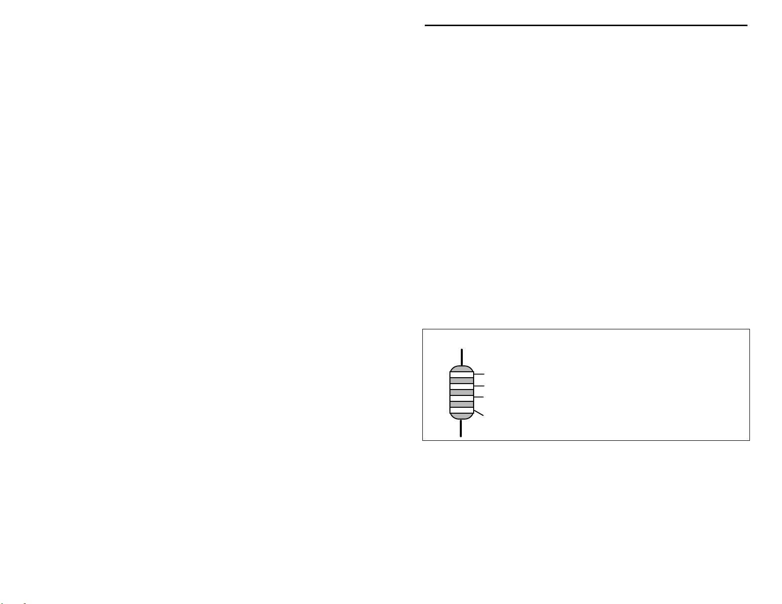
Sorting and Reading Resistors:
a color code (shown below). You don't have to memorize this code to work with
resistors, but you do need to understand how it works:
If you make a mistake and need to remove a part, follow
Kit construction requires the ability to follow detailed
The electrical value of resistors is indicated by
Resistor Color Code
Blue = 6
Violet = 7
Gray = 8
White = 9
Silver = 10%
Gold = 5%
1st Digit
2nd Digit
Multiplier
Tolerence
(gold or silver)
Black = 0 (tens)
Brown = 1 (hundreds)
Red = 2 (K)
Orange = 3 (10K)
Yellow = 4 (100K)
Green = 5 (1Meg)
When you look at a resistor, check its multiplier code first. Any resistor with a
black multiplier band falls between 10 and 99 ohms in value. Brown designates
a value between 100 and 999 ohms. Red indicates a value from 1000 to 9999
ohms, which is also expressed as 1.0K to 9.9K. An orange multiplier band
designates 10K to 99K, etc. To sort and inventory resistors, first separate them
into groups by multiplier band (make a pile of 10s, 100s, Ks, 10Ks, etc.). Next,
sort each group by specific value (1K, 2.2K, 4.7K, etc.). This procedure makes
the inventory easier, and also makes locating specific parts more convenient later
3
Page 6
VEC-412K Owner's Manual Rapid Battery Charger/Conditioner Kit
on during construction. Some builders find it especially helpful to arrange
resistors in ascending order along a strip of double-sided tape.
Some VEC kits may contain molded chokes which appear, at first glance, similar
to resistors in both shape and band marking. However, a closer look will enable
you to differentiate between the two--chokes are generally larger in diameter and
fatter at the ends than resistors. When doing your inventory, separate out any
chokes and consult the parts list for specific color-code information.
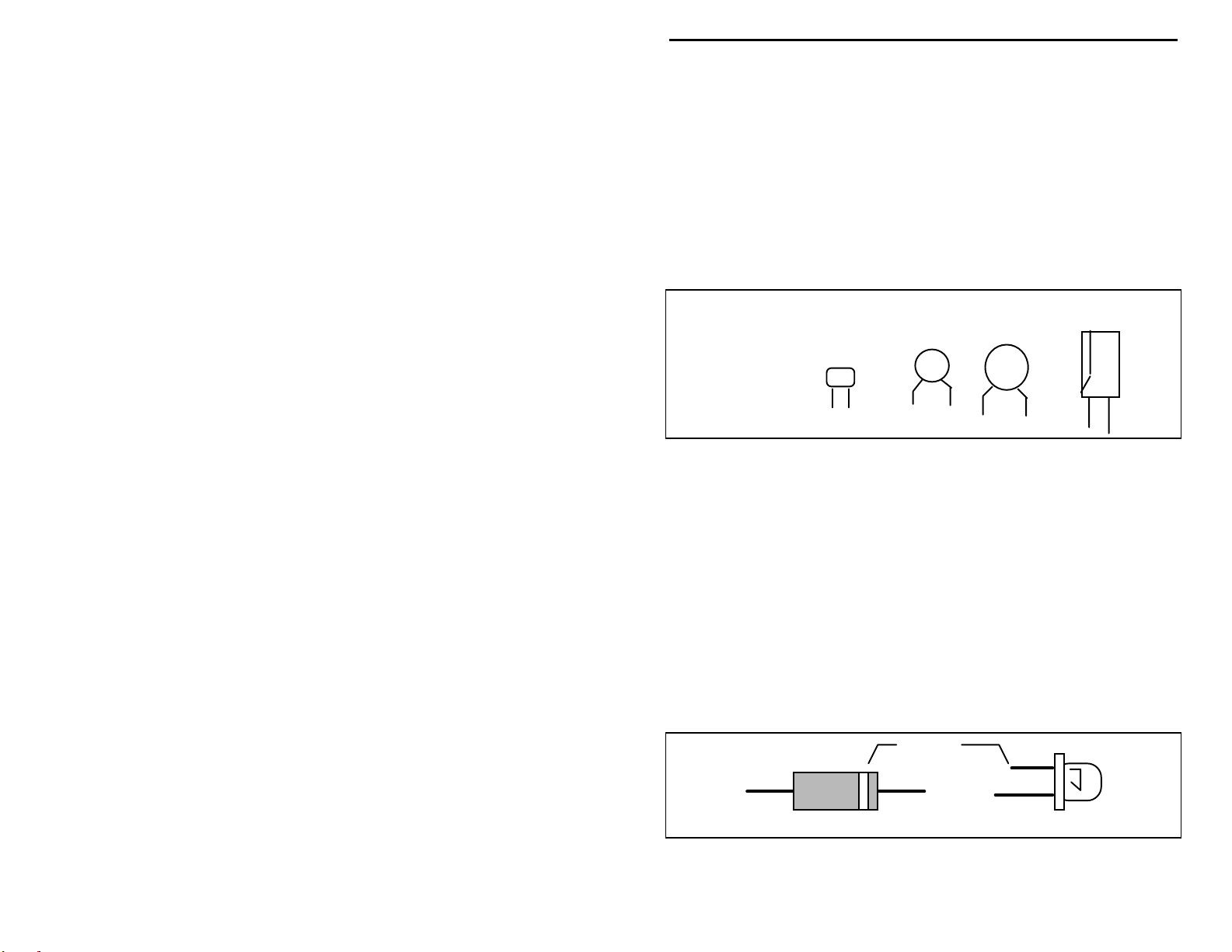
Reading Capacitors:
value identification. Instead, the value, or a 3-number code, is printed on the
body.
Value Code
10 pF = 100
100 pF = 101
1000 pF = 102
.001 uF = 102*
.01 uF = 103
.1 uF = 104
As with resistors, it's helpful to sort capacitors by type, and then to arrange them
in ascending order of value. Small-value capacitors are characterized in pF (or
pico-Farads), while larger values are labeled in uF (or micro-Farads). The
transition from pF to uF occurs at 1000 pF (or .001 uF)*. Today, most
monolithic and disc-ceramic capacitors are marked with a three-number code.
The first two digits indicate a numerical value, while the last digit indicates a
multiplier (same as resistors).
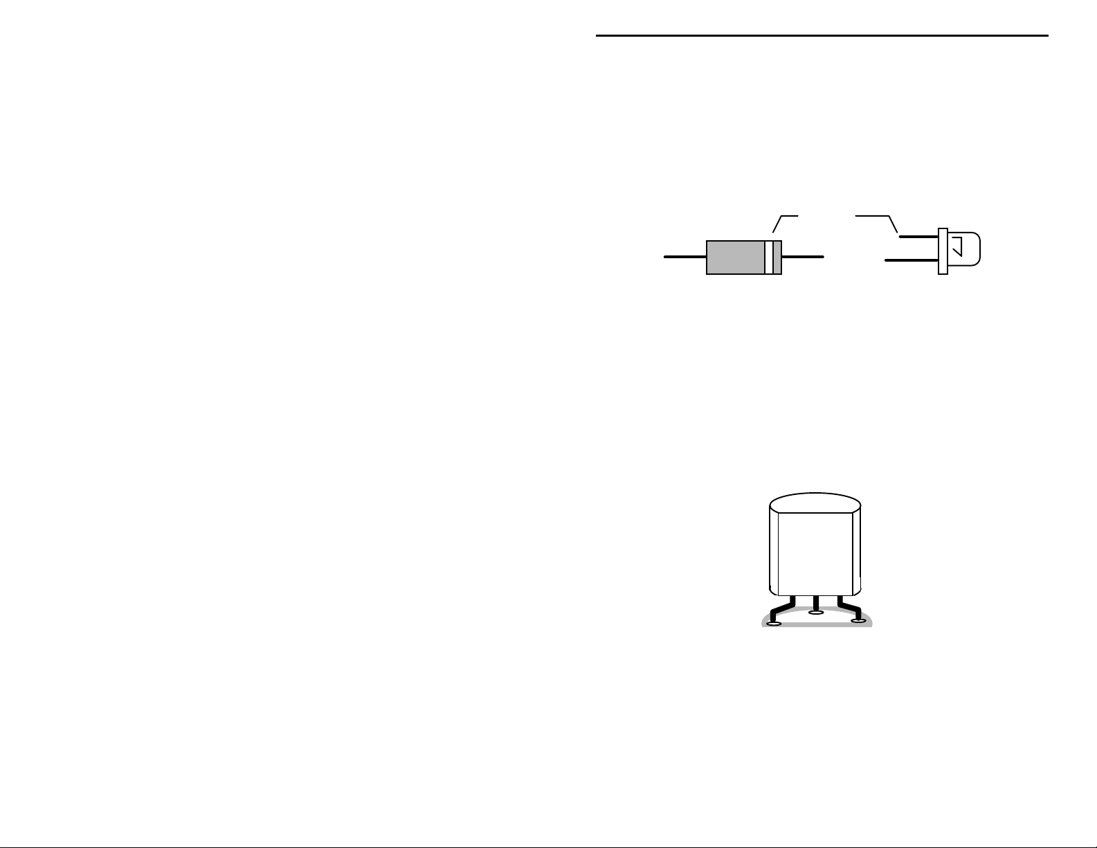
Electrolytic capacitors are always marked in uF. Electrolytics are polarized
devices and must be oriented correctly during installation. If you become
confused by markings on the case, remember the uncut negative lead is slightly
shorter than the positive lead.
Diodes:
Always look for the banded or cathode end when installing, and follow
instructions carefully.
Diodes are also polarized devices that must be installed correctly.
Unlike resistors, capacitors no longer use a color code for
Electrolytic
1 uF
1uF
|
35V
|
+
-
Multilayer
(270 pF)
271
Ceramic Discs
(.001 uF) (.1 uF)
102
104
Cathode
(shorter Lead)
Diode
4
LED
Page 7
VEC-412K Owner's Manual Rapid Battery Charger/Conditioner Kit
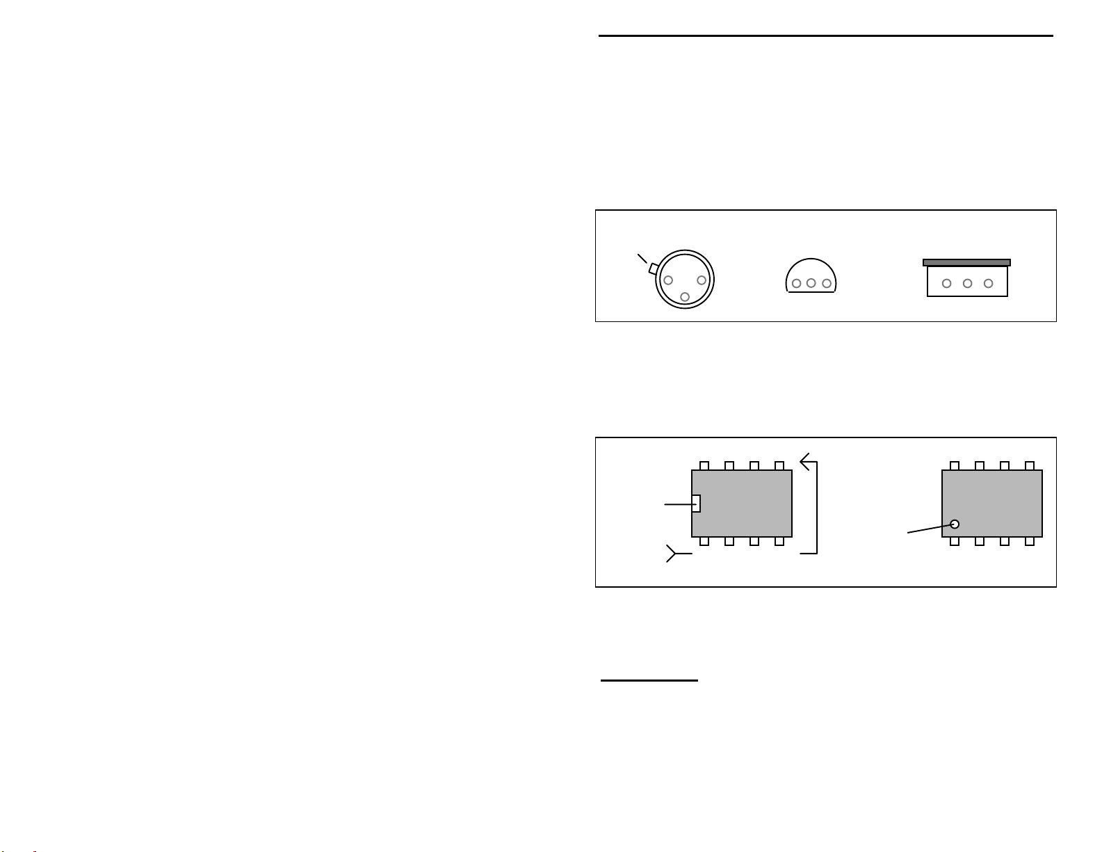
Transistors:
power is applied. Transistors in metal cases have a small tab near the emitter
lead to identify correct positioning. Semiconductors housed in small plastic
cases (TO-92) have an easily-identified flat side to identify mounting orientation.
Many specialized diodes and low-current voltage regulators also use this type
packaging. Larger plastic transistors and voltage regulators use a case backed
with a prominent metal tab to dissipate heat (T-220). Here orientation is
indicated by the positioning of the cooling tab.
Emitter
Integrated Circuits:
marking located on one end of the device. A corresponding mark will be silkscreened on the PC board and printed on the kit's parts-placement diagram. To
identify specific IC pin numbers for testing purposes, see the diagram below.
Pin numbers always start at the keyed end of the case and progress counterclockwise around the device, as shown:
If transistors are installed incorrectly, damage may result when
Metal Can Device Plastic Device Tab-cooled Device
Metal Tab
Flat Side
Proper IC positioning is indicated by a dot or square
8 7 6 5
Installation
Key
1 2 3 4
Pin Numbers
Installation
Key
PARTS LIST
Your package kit should c ontain a ll of the p arts li sted be low. Ple ase go through
the parts bag to identify and inventory each item on the checklist before you start
building. If any par ts are missing or damaged, r efer to the warranty section of
this manual for replacement instructions. If you can't positively identify an
unfamiliar item in the bag on the basis of the information given, set it aside until
5
Page 8

VEC-412K Owner's Manual Rapid Battery Charger/Conditioner Kit
all other items are checked off. You may then be able to identify it by process of
elimination. Finally, your kit will go together more smoothly if parts are
organized by type and arranged by value ahead of time. Use this inventory as an
opportunity to sort and arrange parts so you can identify and find them quickly.
Ignore the fourth color band when reading resistors, it denotes the
Note
:
tolerance value and is not needed for parts inventory or assembly
directions.
Resistors:
Qty Part Description Designation
"
!
6 1.5-ohm 1/4 Watt
(brown-green-gold)
!
2 18-ohm 1/2 Watt
(brown-gray-black)
!
1 220-ohm 1/4 Watt
(red-red-brown)
!
1 820-ohm 2 Watt
(gray-red-brown)
!
3 1K-ohm 1/4 Watt
(brown-black-red)
!
1 27K-ohm 1/4Watt
(red-violet-orange)
!
11 47K-ohm 1/4Watt
(yellow-violet-orange)
!
2 100K-ohm 1/4 Watt
(brown-black-yellow)
!
1 270K-ohm 1/4 Watt
(red-violet-yellow)
R16,R22,R23,R24,R25,
R26
R21,R28
R1
R20
R3,R12,R17
R5
R2,R4,R6,R7,R8,R9,R10,
R11,R14,R15,R18
R19,R27
R13
Capacitors:
Qty Part Description Designation
"
!
5 .1-uF disc ceramic (104 or .1) C3,C4,C5,C6,C7
!
2 100-uF electrolytic C1,C2
Inductors:
Qty Part Description Designation
"
!
1 500-uH choke L1
Semiconductors:
Qty Part Description Designation
"
!
2 1N4001, diode rectifier D1,D4
6
Page 9

VEC-412K Owner's Manual Rapid Battery Charger/Conditioner Kit
!
1 1N5822, diode Schottky D2
!
1 1N5223B, 2.7 volt zener diode D3
!
1 2N3055, power transistor (TO-3) Q1
!
1 2N3904, transistor Q2
!
1 IRF9530, power FET Q3
!
1 BQ2003 IC (16-pin DIP package) U1
!
1 78L05, +5Vdc voltage regulator U2
!
1 LED, red CR1
!
1 LED, yellow CR2
Switches/Jacks/Misc.:
Qty Part Description Designation
"
!
1 2.1mm coaxial power jack J1
!
1 Rotary switch 2 pole, 6 position SW1
!
3 DPDT push-action switches SW2,SW3,SW4
!
1 16-pin IC socket For U1
!
6 3 position header HD1,HD2,HD3,HD4,HD5,
HD6
!
6 2 position shorting jumper
!
1 20 AWG red-black cable
!
3 4-40 phillips x 1/4”screw
!
3 4-40 phillips hex nut
!
1 PC board for VEC-412K
!
1 VEC-412K Owner's Manual
7
Page 10
Page 11
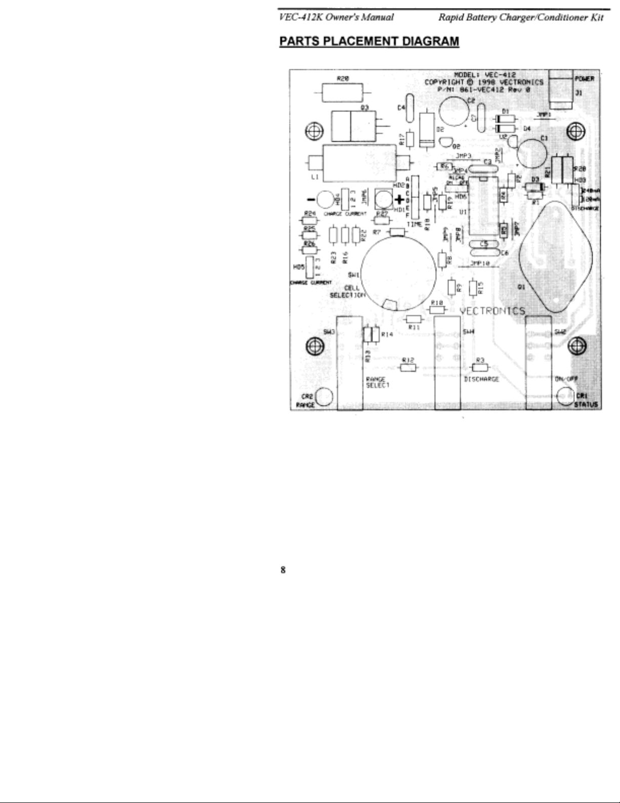
VEC-412K Owner's Manual Rapid Battery Charger/Conditioner Kit
STEP-BY-STEP ASSEMBLY
Before assembling your kit, please take time to read and understand the VEC kit
warranty printed on the inside cover of this manual. Also, read through the
assembly instructions to make sure the kit does not exceed your skill level. Once
you begin construction, your kit will be non-returnable. Finally, if you haven't
already done so, please verify that all parts listed in the inventory are included.
If anything is missing or broken, refer to the warranty instructions for replacing
missing or damaged parts.
Note that part designators, such as R1, C3, etc., appear on a silk-screened legend
on the component-mounting side of the printed circuit board. This corresponds
with the parts placement page in the manual. All parts will be inserted on the
silk-screen side of the board.
If you have last-minute questions about tools and materials needed to build your
kit, please refer back to the section titled "Before You Start Building". If you're
ready to begin now, let's get started! The directions use two sets of check boxes.
Check one when a step is complete and use the other for double-checking your
work before operation.
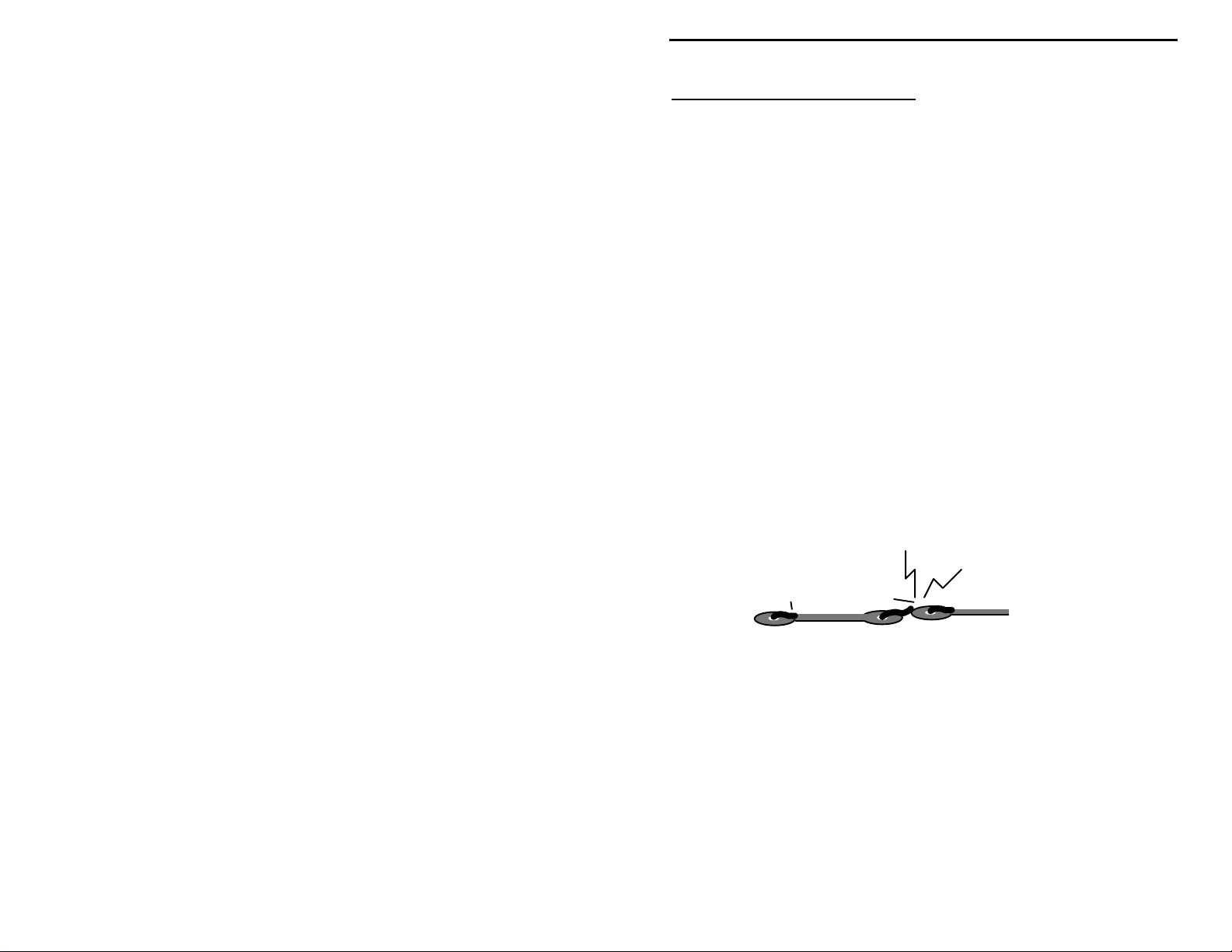
“Install”
and insert the part into its mounting holes on the PC board. T his includes prebending or straightening leads as needed so force is not required to seat the part.
Once a component is mounted, bend each lead over to hold it in place. Make
sure trimmed leads don’t touch other pads and tracks, or a short circuit may
result:
“Solder”
in place, and to inspect both (or all) solder connections for flaws or solder
bridges. If no soldering problems are noted, nip off the excess protruding leads
with a sharp pair of side cutters.
Notice that the directions use two check boxes. Check one when a step is
complete and use the other for double-checking your work before operation.
¼-Watt Resistor Installa tion:
When you are directed to install a part, this means to locate, identify,
Good
When you are directed to solder, this means to solder the part’s leads
Not Good
9
Page 12

VEC-412K Owner's Manual Rapid Battery Charger/Conditioner Kit
You will begin assembly by installing the ¼-watt fixed resistors. Because these
are all 5-percent tolerance ending with a fourth gold color band, you need only
read the first three bands of the color code during the following steps. All
resistor leads should be formed as shown below.
.4"
The fourth resistor color band is for tolerance, and is not called out in the
:
Note
following steps.
Begin by finding the six 1.5-ohm resistors (brown-green-gold-gold). Install and
solder at the following locations:
! !
1. R16 1.5-ohm resistor (brown-green-gold)
! !
2. R22 1.5-ohm resistor (brown-green-gold)
! !
3. R23 1.5-ohm resistor (brown-green-gold)
! !
4. R24 1.5-ohm resistor (brown-green-gold)
! !
5. R25 1.5-ohm resistor (brown-green-gold)
! !
6. R26 1.5-ohm resistor (brown-green-gold)
! !
7. Locate the 220-ohm resistor (red-red-brown). Install and solder at
location R1.
Locate the three 1,000-ohm (1K-ohm) resistors (brown-black-red). Install and
solder at the following locations:
! !
8. R3 1K-ohm (brown-black-red)
! !
9. R12 1K-ohm (brown-black-red)
! !
10. R17 1K-ohm (brown-black-red)
! !
11. Locate the 27,000-ohm (27K-ohm) resistor (red-violet-orange). Install
and solder at location R5.
Locate the eleven 47,000 ohm (47K-ohm) resistors (yellow-violet-orange).
Install and solder at the following locations:
! !
12. R2 47K-ohm (yellow-violet-orange)
! !
13. R4 47K-ohm (yellow-violet-orange)
! !
14. R6 47K-ohm (yellow-violet-orange)
10
Page 13

VEC-412K Owner's Manual Rapid Battery Charger/Conditioner Kit
! !
15. R7 47K-ohm (yellow-violet-orange)
! !
16. R8 47K-ohm (yellow-violet-orange)
! !
17. R9 47K-ohm (yellow-violet-orange)
! !
18. R10 47K-ohm (yellow-violet-orange)
! !
19. R11 47K-ohm (yellow-violet-orange)
! !
20. R14 47K-ohm (yellow-violet-orange)
! !
21. R15 47K-ohm (yellow-violet-orange)
! !
22. R18 47K-ohm (yellow-violet-orange)
Locate the two 100,000-ohm (100K-ohm) resistors (brown-black-yellow).
Install and solder at the following locations:
! !
23. R19 100K-ohm (brown-black-yellow)
! !
24. R27 100K-ohm (brown-black-yellow)
! !
25. Locate the 270,000-ohm (270K-ohm) resistor (red-violet-yellow).
Install and solder at location R13.
Save the ¼-watt resistor lead clippings for the next phase of assembly.
Installing of Larger-Wattage Resistors:
Locate the two 18-ohm ½-watt resistors (brown-gray-black). Install and solder
at the following locations:
! !
1. 18-ohm resistor (brown-gray-black) at R21.
! !
2. 18-ohm resistor (brown-gray-black) at R28.
! !
3. Locate the 820-ohm 2-watt resistor (gray-red-brown). This resistor’s
body is much larger than the ¼-watt styles. Install and solder at
location R20.
This completes the resistor installation. There should be no resistors left in the
kit. Go back over each solder connection, and verify that all resistor are in the
correct locations. Recheck each solder joint for bridges, and redo any suspect
solder connections.
Installation of Wire Jumpers:
11
Page 14

VEC-412K Owner's Manual Rapid Battery Charger/Conditioner Kit
Use scrap resistor lead ends for use as jumper wires, as shown in the following
diagram. Use needle-nose pliers to form each one to fit properly at each
location, making sure each rests flat on the PC board when installed:
span
Install and solder wire jumpers at the following locations:
! !
1. JMP1 jumper wire
! !
2. JMP2 jumper wire
! !
3. JMP3 jumper wire
! !
4. JMP4 jumper wire
! !
5. JMP5 jumper wire
! !
6. JMP6 jumper wire
! !
7. JMP7 jumper wire
! !
8. JMP8 jumper wire
! !
9. JMP9 jumper wire
! !
10. JMP10 jumper wire
Capacitor Installation:
Locate the five .1-uF ceramic disc capacitors (104 or .1). Install and solder at
the following locations:
! !
1. C3 .1-uF ceramic disc capacitor (104 or .1)
discarded lead end
! !
2. C4 .1-uF ceramic disc capacitor (104 or .1)
! !
3. C5 .1-uF ceramic disc capacitor (104 or .1)
! !
4. C6 .1-uF ceramic disc capacitor (104 or .1)
! !
5. C7 .1-uF ceramic disc capacitor (104 or .1)
Locate the two 100-uF electrolytic capacitors. Note that these are polarized
devices—they must be installed with regard to lead polarity! Carefully observe
the polarity markings on the board silk-screen, and the pictorial diagram before
soldering! Install and solder at the following locations:
! !
6. C1 100-uF electrolytic capacitor. Observe polarity!
! !
7. C2 100-uF electrolytic capacitor. Observe polarity!
12
Page 15

VEC-412K Owner's Manual Rapid Battery Charger/Conditioner Kit
This completes installation of the capacitors. Recheck all work done so far and
correct any misplaced components or bad solder joints.
Header Installation:
Locate the six 3-position headers. Install and solder at the following locations:
Short pins into pc
boar d holes
! !
1. HD1 Three-position header
! !
2. HD2 Three-position header
! !
3. HD3 Three-position header
! !
4. HD4 Three-position header
! !
5. HD5 Three-position header
! !
6. HD6 Three-position header
Semiconductor Installation:
All semiconductors are polarized devices. They must be installed as
Note
:
directed. Use the pictorial drawing and the silk-screened legend on the pc
board to verify proper installation of these devices!
Locate the two 1N4001 silicon rectifier diodes. Install and solder at the
following locations—observe the orientation of the cathode lead:
Cathode
1N4001
! !
1. D1 1N4001 diode, observe polarity!
! !
2. D4 1N4001 diode, observe polarity!
13
Page 16
VEC-412K Owner's Manual Rapid Battery Charger/Conditioner Kit
! !
3. Locate the 1N5822 diode (largest bodied diode in kit). While
observing cathode lead orientation, insert and solder at location D2.
! !
4. Locate the 1N5223B diode. While observing cathode lead orientation,
insert and solder at location D3.
Locate the RED LED. Observe that the cathode lead is the shorter of the two
device leads. The cathode lead is also indicated by a small flat area in the
otherwise round base of the device.
Cathode
(shorter Lead)
Diode
! !
5. Install the RED LED at location CR1 on the PC board. Verify that the
body outline corresponds to the PC board legend and pictorial
diagram. Install the LED leads until the shouldered stops on the leads
are flush to the PC board. Bend the leads so the LED is flush with the
edge of the PC board. Solder.
! !
6. Locate the YELLOW LED . Install and solder at location CR2 on the
PC board. Observe polarity.
! !
7. Locate the 2N3904 transistor. Install and solder at location Q2. Note
the device has a rounded and flat side. Observe proper orientation
using the PC board legend and pictorial diagram.
2N3904
Q2
! !
8. Locate the 78L05 three-terminal voltage regulator IC. Observing
polarity, install and solder at location U2.
LED
14
Page 17

VEC-412K Owner's Manual Rapid Battery Charger/Conditioner Kit
y
78L05
U2
Locate the 16-pin DIP IC socket. Notice that the socket is “keyed” to show
proper pin orientation.
14 13 12 11 10 9 8
Installation
Key
1 2 3 4 5 6 7
Pin Numbers
! !
9. Install and solder the 14-pin IC socket at location U1. Observe that
the key aligns with the legend outline on the pc board.
Locate the BQ2003 IC (14-pin DIP package).
Installation
Ke
The IC body has a small notch, or key, molded at one end, indicating pins 1 and
14. A small dimple-like body-molding is often found adjacent to pin 1. Some
IC packages may include both key indicators.
BENCHMARQ
BQ2003PN
1
Top vi ew of soc ket
! !
10. Align the key on the IC body so it corresponds with the key of socket
U1. Loosely insert the pins of the BQ2003 into socket U1. All 14
pins should fit freely into the socket openings. If not, straighten the IC
15
Page 18

VEC-412K Owner's Manual Rapid Battery Charger/Conditioner Kit
pins until they do. Using firm and steady pressure, fully seat the IC
into the socket.
Locate the 2N3055 silicon power transistor. Note that the emitter and base leads
are not centered on the device body.
! !
11. Install the 2N3055 transistor at location Q1. Note that the device leads
must be inserted so that Q1’s heatsink aligns properly with the PC
board mounting holes.
! !
12. Find two 4-40 ¼” screws and two 4-40 nuts. Mount Q1 to the PC
board using the 4-40 hardware. The nuts should be on the foil side of
the board. T ighten the har dware until snug—the hard ware p ro vide s an
electrical path for the collector of this transistor.
! !
13. After the hardware is tightened, solder and trim the emitter and base
leads of the 2N3055 transistor.
Locate the IFR9530 power FET.
Tab-cooled Device
Metal Tab
IFR9530
Temporarily place the IFR9530 at mounting location Q3. The device leads
should be formed to align with three component lead holes, and the mounting
hole on the heatsink tap should align with the mounting hole drilled in the PC
board. Re-form leads as needed.
! !
14. Install the IFR9530 at location Q3. Use the remaining 4-40 x ¼”
screw and 4-40 nut supplied in the kit to mount the device (the nut
should be placed on the IFR9530 heatsink tab). Tighten the hardware
until snug (the hardware provide s an electrical path) . Solder and trim
the component leads.
Final Assembly:
! !
1. Locate the 500-uH wire-wound choke. Install and solder the choke at
location L1.
! !
2. Locate the 2.1mm coaxial style power connector jack. Install at
location J1. Be sure the jack body is mounted flush to the board.
Carefully bend over the solder-tabs for J1 so they are flush with the
solder area on the PC board—this improves the mechanical strength of
the solder connections. Solder the three tabs for J1.
16
Page 19
VEC-412K Owner's Manual Rapid Battery Charger/Conditioner Kit
Locate two of the DPDT push-action switches. Install and solder at the
following locations (be sure switch body is mounted level to board before
soldering):
Important Note:
directed to do so!
! !
3. SW2 DPDT push-action switch
! !
4. SW3 DPDT push-action switch
Do not install a push-action switch at location SW4 until
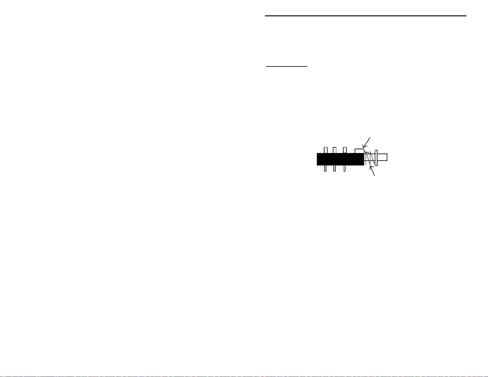
Locate the remaining DPDT push action switch. Activate the switch shaft
several times and observe the off/on latching mechanism.
Reposition t his clip for momentary operation
spring
Side view of SW4 switch
This switch will be used at position SW4 to initiate a discharge cycle. The
switch must be modified from latching action to momentary action. Note the
clip shown in the diagram above. The front part of the clip (over the shaft and
under the spring) holds the shaft from falling out of the switch body. The rear
portion of the clip enters the switch body and sets the latching action. Carefully
use a pair of tweezers or fine long-nosed pliers to lift the rear of the clip free of
the switch body (do not lift the front end) and reposition the clip so it falls on the
outside of the switch body (see the following diagram).
17
Page 20

VEC-412K Owner's Manual Rapid Battery Charger/Conditioner Kit
! !
5. Install and solder the modified momentary-action switch at location
SW4 (make sure the switch body remains level to the board while
soldering).
! !
6. Locate the 6-position d ouble-pole rotary switch. Hold the switch, and
rotate the shaft fully counterclockwise until the stop is reached. Rotate
the switch clockwise counting the number of positions. There should
be six positions. If not, rotate the shaft back to the fully
counterclockwise position. Remove the mounting nut and lockwasher
on the shaft bushing. This will reveal a second silver colored
indexing-washer. This washer has an pin that corresponds to the
desired stop position number etched on the switch body. If the washer
pin is in a position other than position six, remove the pin, and try
rotating the shaft counterclockwise. It may already be there, or the
index pin may have been setting a false CCW stop. Realign the
indexing washer pin into the proper pin sixth stop-position. Replace
the lockwasher and mounting nut to hold the index washer in position.
The switch should now have six positions.
! !
7. Rotate the shaft of the 6-position switch fully counterclockwise. The
“flat” of the shaft should now be aligned so it faces the small plastic
post on the switch body.
! !
8. Install the switch at location SW1—the flat of the shaft and plastic
post should face the rear of the board, that is facing away from SW2
and SW4. Note that all pins of the switch must enter their respective
solder holes. Straighten any bent pins before attempting insertion.
With the switch body mounted flush to the board, solder all pins.
! !
9. Locate the length of married RED/BLACK zip cable. At one end,
carefully split the wires apart for a length of two inches. Remove ¼”
of insulation from each wire.
18
Page 21

VEC-412K Owner's Manual Rapid Battery Charger/Conditioner Kit
! !
10. Locate the legend for the negative battery wire ( - ) on the PC board.
This is located in front of choke L1. Tightly twist the strands for the
BLACK wire together, and insert in the opening marked ( - ). Solder
and trim the black wire.
! !
11. Locate the legend for the positive battery wire ( + ) on the PC board.
Tightly twist the strands for the RED wire together, and insert in the
opening marked ( + ). Solder and trim the red wire.
The other end of the married RED/BLACK cable will be used to connect the
battery pack to the charger. At this time you may wish to provide a suitable
connector to mate with the battery pack the charger is to be used with. The red
lead connects to the positive battery termination, the black lead connects to the
negative battery termination.
This completes the assembly of the VEC-412K Rapid Charger/Battery
Conditioner. Before proceeding, please take some time for a quality-control
inspection. Carefully verify that all parts are in the correct locations. Check
each solder joint for unwanted bridges. Correct any poor solder joints.
TESTING
Performing a test of the VEC-412K Rapid Charger/Battery Conditioner requires
a good understanding of what the various switches and jumper settings are used
for. We suggest r eading the
to become familiar with the unit’s operation and setup procedures.
Operating Instructions
on page 20 of the manual
1. Select a battery pack that is known to be in good condition for the following
tests. Power must be supplied from an external source—the current and
voltage requirements are dependent on the battery pack to be tested. Set the
shorting jumpers on headers HD1, HD2, HD3, HD4, HD5 and HD6 as
directed in the
2. Set range switches SW3 and SW1 to correspo nd to the number of cells in the
test battery pack (see Table 1).
3. Connect the RED battery charger lead to the positive battery terminal.
Connect the BLACK battery charger lead to the negative battery terminal.
4. With the power supply connected, turn power switch SW2 on. The RED
status LED (CR1) should indicate either
Pending
A
Charger Pending
discharged condition (less than one volt per cell). At this point, the charger has
initiated a trickle charge which will continue until each cell reaches a 1-volt
charge. If the battery pack was charged before hand, and the Charge Pending
Operating Instructions
.
status indication occurs when the battery pack is in a
.
Fast Charging
or
Charger
19
Page 22

VEC-412K Owner's Manual Rapid Battery Charger/Conditioner Kit
condition is shown, verify that the settings for range switches SW3 and SW1
correspond correctly with the number of cells in the battery pack. Refer to Table
4 for charge status.
A
Fast Charging
per cell, and fast charging has commenced. Pressing the momentary action
Discharge
discharging condition. This will drain the battery until each cell reaches the 1volt discharge cut-off point. Fast charging will then resume automatically.
Status LED CR1 failing to light (or flash) indicates that the battery is:
1. Absent or open.
2. SW3 and SW1 range switches set for wrong number of cells.
You may place a milliamp meter in series with the battery to verify proper
charge and discharge currents.
switch SW4 should cause the charger to switch from fast charge to a
indication shows that the battery cells are each above 1-volt
OPERATING INSTRUCTIONS
External power requirements:
are determined by the battery being charged. Determine the number of cells in
the battery pack (see Table 1). The supply voltage should be equal to or slightly
greater than 2-volts per cell, plus another volt or two for headroom to
compensate for the charger circuitry. For example, a 6-volt battery pack
contains 5 cells. For this battery pack, the minimum external power supply
voltage should be 11 o r 12 volts. The supply voltage limits are 7 Vdc minimum
and 21 Vdc maximum. Using voltages that greatly exceed the 2-volt-per-cell
recommendation may result in saturation of the switching inductor L1 and
improper charger operation. For packs with 10 or more cells, use a supply
voltage of 21Vdc. For single cells, or battery packs with 3 or less cells, use a
power supply voltage of about 8 Vdc.
The operating voltage and current requirements
The power supply should be capable of handling slightly more current than the
Fast Charge current setting set by the jumpers in Table 2. A 1-amp, or greater,
supply will meet all requirements. Power is supplied to the 2.1mm coaxial
power jack J1. Center pin is positive. Push-action switch SW2 removes or
applies power to the charger (OFF/ON switch).
Setting the Range Switches:
to the cell count of the battery pack. This is determined by dividing the battery
pack’s rated voltage by 1.2. For example, an 8.4-volt battery pack contains 7
cells. Refer to Table 1.
Push-action switch SW3 determines if the battery pack contains between 1 to 6
cells (off) or 7 to 12 cells (on). The six-position rotary switch SW1 is set for 1
20
Range switches SW3 and SW1 are set according
Page 23

VEC-412K Owner's Manual Rapid Battery Charger/Conditioner Kit
to 6 cells, or 7 to 12 cells—depending on the state of SW3. The yellow Range
LED CR2 is lit when SW3 is off.
For battery packs containing
to
(shaft fully extended). When off, the YELLOW Range indicator LED
off
CR2 will be lit. When SW3 is off the rotary range switch SW1 selects from 1 to
6 cells. Example: Rotary range switch SW1 is set to position 6 for a six-cell
battery pack, and SW3 would be off (CR2 lit).
For battery packs containing
depressed. Yellow Range LED CR2 will be extinguished when SW3 is on.
With SW3 on, the rotary switch SW1 selects from 7 (fully CCW at position 1) to
12 cells (fully CW, at position 6). Example: For a 9.6-volt battery pack
containing 8 cells switch SW3 would be set to on (CR1 not lit) and range switch
SW1 would be set to position 2.
Battery Pack Voltage Number of cells SW3 setting SW1 setting
1.2 1 Off 1
2.4 2 Off 2
3.6 3 Off 3
4.8 4 Off 4
6 5 Off 5
7.2 6 Off 6
8.4 7 On 1 (7)
6 or less cells
7 or more cells
, push-action range switch SW3 is set
, range switch SW3 must be on, or
9.6 8 On 2 (8)
10.8 9 On 3 (9)
12 10 On 4 (10)
13.2 11 On 5 (11)
14.4 12 On 6 (12)
Table 1.
Setting the Charge Rate Current:
charge rate currents: 250mA, 500mA and 1,000mA (1 amp). The Charge Current
The VEC-412K charger has three different
21
Page 24

VEC-412K Owner's Manual Rapid Battery Charger/Conditioner Kit
is programmed by placing jumpers over Headers HD4 and HD5 as shown in
Table 2.
Charge Rate Current HD4 HD5
250 mA 1-2 2-3
500 mA 1-2 1-2
1,000 mA 2-3 1-2
Table 2.
How the shorting clip is placed over jumper pins:
Shorting
block
Charge Rate Current
CURRENT.
The Charge Rate Current is determined by the formula:
is set with the headers
Capacity of Battery (mAh)
I
cr =
Charge Time (hours)
WARNING: A too high charge current setting could
cause cells to explode or rupture. Consult
the battery manufacturer for the charging
current specifications of your battery!
HD4
and
labeled CHARGE
HD5
Setting the Fast Charge Rate and Time Out:
capacity, or C rating, associated with them. This value is defined in a milli-Amp
hour rating, or mAh. The Fast Charge Rate is determined by the capacity C of
the battery and by the time selected to charge the battery. The maximum Fast
22
Rechargeable batteries have a
Page 25

VEC-412K Owner's Manual Rapid Battery Charger/Conditioner Kit
Charge Rate recommended by the manufacturer should not be exceeded. Use
the charge rate C/2 if this information is not available.
Fast Charge Rate Time-Out HD1 HD2
C/2 180 mins. OPEN AB
C 90 mins. DE BC
2C 45 mins. DE OPEN
4C 23 mins. DE AB
Table 3. Fast charge rate Time-Out settings
Fast Charge Rate
and
Time Out
are set with headers HD2 and HD1.
For example, a 500-mAh battery may be safely fast-charged at the 2C Fast
Charge Rating according to the manufacturer. The Charge Rate Current should
be set to 2x the mAh rating, or 1000 mA (HD4 2-3, HD5 1-2). The Fast Charge
Rate Time-Out should be set to 2C and 45 minutes (HD2 open, HD1 D-E).
Battery Top Off:
Once a fast-charge cycle has completed, the charger will
continue periodically charging the attach battery as needed, assuring the battery
remains at full capacity. The Top Off charging current is a very low level and
will not damage charged battery packs.
Negative Increment of Voltage Detectio n Method
This method of determining
:
when a NiCd battery has reached full charge is controlled by the HD6 jumper
position. When the jumper is in the ON position the Negative Increment of
Voltage Detection Method is enabled.
IMPORTANT INFORMATION!
The Negative Increment of Voltage Detection Method can only be used for
NiCad batteries. A large negative drop at the end of charge is characteristic
of NiCads, and the charger senses this condition to determine the successful
completion of a fast charge cycle. HD6 must be OFF when charging NiMH
packs, as overcharging may result in dangerously high battery pack
temperatures.
The Negative Increment of Voltage Detection Method is enabled by placing the
jumper over the ON position of the HD6 header:
23
Page 26

VEC-412K Owner's Manual Rapid Battery Charger/Conditioner Kit
HD6 must be OFF when fast charging NiMH battery packs!
do not exhibit a voltage drop at full charge. NiMH battery temperatures can
rapidly soar to dangerous levels if overcharged.
NiMH batteries
Discharge-Before-Charge:
when seldom used and left charging for long periods of time. Activating
momentary action switch SW4 will fully discharge the attached battery pack to
the 1-volt-per-cell fully-discharged condition. NiCad battery packs should never
be allowed to discharge below one-volt-per-cell or damage to the cells may
occur. Allowing the pack to fully charge, and then performing a full discharge
cycle by activating SW4 will exercise the cells, and help correct memory
conditions. Several full charge/discharge cycles may be needed to fully erase a
memory condition in troublesome battery packs. Note that once a discharge
cycle has completed, the charger will automatically recharge the battery pack.
Continued high charge and discharge rates will cause cell heating. Allow the
battery time to cool between repeated memory cleansing cycles.
Setting the Discharge Current:
120mA or 240mA. The jumper position on HD3 sets the discharge rate. Check
the battery specifications for the maximum recommended discharge rate. A
discharge rate equal to or less than the battery Capacity (C) is generally
acceptable. Using the lowest discharge setting is advisable. The longer
discharge time allows the cells to equalize their voltages, and gives the pack time
to cool off after completion of a rapid charge.
Starting the Discharge Cycle:
cell, depressing momentary-action switch SW4 will initiate a controlled
discharge cycle until the 1 volt-per-cell discharge point is reached.
STATUS Indicator LED CR1: O
will show the charger’s current activity. See Table 4.
NiCad batteries can develop a so-called “memory”
Two discharge current rates are available:
Providing the battery pack is above 1 volt-per-
bserving the condition of Status LED CR1
Charger Status Red status LED CR1 indication
Battery absent or
wrong number of cells set-up
24
OFF
Page 27

VEC-412K Owner's Manual Rapid Battery Charger/Conditioner Kit
Charger Pending(trickle charge) OFF for 1.375 sec and ON for 0.125 sec
Fast Charge ON continuous
Discharge Cycle ON for 1.375 sec and OFF for 0.125 sec
Charge complete and Top-Off ON for 0.125 sec, OFF for 0.125 sec
Table 4.
The
Determining Full Charge:
full charge are used: Maximum Voltage Determination Method, Time-Out, and a
Negative Increment of Voltage Detection Method. The fast charging rate will
cease if any of one of these three conditions are meet.
The Negative Increment of Voltage Detection Method will not work on NiMH
battery packs. During fast charge NiMH battery packs are monitored for
maximum pack voltage, and the charging time is also limited by the Time Out
setting.
Maximum Voltage Determination Method:
1.82 volts-per-cell the charger concludes the fast charge cycle and enters the Top
Off charging mode.
Time Out:
is also determined. This is a fail-safe safety feature that prevents overcharging.
If for some reason the battery fails the Voltage Determination Method or the
Negative Increment of Voltage Detection Method for determining full charge,
the Time-Out timer will end the fast charge cycle before battery damage occurs.
The Time-Out timer allows sufficient time for a pack to reach a fully charged
condition, unless defective.
Getting the Best Charge:
high temperatures. Do not charge batteries that are very warm or cold. Let
batteries stabilize at room temperature before charging. Allow batteries a
cooling off period between multiple charge/discharge memory cleansing cycles.
of the controller is shown by the state of CR1, the red
status
For NiCd batteries, three methods of determining
See Table 3. When setting the Fast Charge Rate, a Time-Out setting
NiCad battery capacity is reduced at very low or
Status
When the battery pack reaches
LED.
Determining Battery Capacity:
charged battery pack. Multiply the number of hours by the discharge rate to
find the mAh capacity of the battery. For example, a battery takes 2.3 hours to
discharge at the 240 mA discharge setting. 2.3 hours x 240 mA = 552 mAh
(battery capacity C). Note: for best accuracy, use mA meter in series with the
battery to find the exact discharge current.
Battery Failure:
last 3, 4 or 5 years. Internal shorts often occur in older battery cells, or cells
With pro per ca re it is not unusual for NiCad battery pa cks to
Time how long it takes to fully discharge a
25
Page 28

VEC-412K Owner's Manual Rapid Battery Charger/Conditioner Kit
may develop a very high internal resistance (open condition). These are failures,
and can not be repaired by conditioning the battery. Battery packs that are
discharged in heavy service beyond the 1 volt-per-cell discharge limit may have
cells that became “reverse charged” and severely damaged in the process.
Again, this damage cannot be repaired.
NiCads have a maximum number of discharge and charge cycles for their
designed lifetime. Most NiCad damage occurs because NiCads are left charging
for long periods of time—resulting in overheated cells or severe memory
conditions. NiCads that do not respond to repeated cycling should be disposed
of properly, they are considered to be a hazardous waste material. Your local
landfill should have procedures in place to handle these materials.
Do not recharge primary cells (alkaline, etc.), or lead acid type batteries using
the VEC-412K charger.
Glossary of Terms:
Battery Capacity:
specified time interval, usually one hour, resulting in full discharge.
Battery Pack:
Charge Current:
Charge Rate Current:
Cycling:
a memory condition.
Memory:
Negative Increment of Voltage Detection:
battery pack that occurs when it is fully charged as a method for ending the charge cycle.
NiCad or NiCd:
NiMH:
Time Out:
interval lapses.
Top Off:
Repeated and controlled charge/discharge cycling of a NiCd battery to remove
A condition where NiCd batteries lose capacity, mostly due to misuse.
Nickel Metal Hydroxide
A fail-safe timer setting that concludes the fast charge cycle after a set time
A periodic charging cycle to keep a battery at its maximum charge capacity.
A Practical Example:
Expressed as a fixed rate of current a battery can supply over a
An assembly containing two or more cells in series.
The current applied to a battery being charged.
Capacity of battery in mAh divided by charge time in hours.
Sensing the voltage drop across a NiCd
Nickel Cadmium
Setting up the charger may appear to be a confusing task,
but it is really much easier than it first appears.
Our example is a 6-volt 600-mA cordless phone battery. Table 1 shows this
battery contains 5 individual cells. Since each cell requires 2-volts of supply
26
Page 29

VEC-412K Owner's Manual Rapid Battery Charger/Conditioner Kit
voltage, plus an extra 2-volts to compensate for losses in the charger circuitry,
we will need a power supply capable of supplying 8 Vdc.
Since the cell count is between 1 and 6, Range Switch SW3 is set to the OFF
position. Rotary Switch SW1 is set to position 5 as shown in Table 1 for a 5-cell
battery pack.
We know the battery has a 600-mAh rating. What this means, in theory, is that
the battery will supply 600-mA of current for one hour. Conversely, applying
600-mA of charging current for one hour should fully charge the battery. This is
also theoretical. Charging involves losses, such as heat, and heat is wasted
energy. Charging may require 70 or 80 minutes at a 600 mA charge rate current.
Likewise, in reality a 600-mAh battery may be able to only deliver a maximum
300-mA current over a two-hour span.
The battery fast charge rate is not given on the battery label. To be safe, we will
use the C/2 charge rate, 300 mA. Table 2 shows the closest Charge Rate Current
is 250 mA. Table 3 shows for the C/2 fast charge rate the Time Out safety timer
is 180 minutes, or 3 hours. 3 hours x 250 mA = 750 mAh. 150 mAh should
provide e nough margin to fully charge the 600 mAh battery.
At this point we also know our charger power supply must be rated for
something greater than 250 mA.
For the 250-mA charge current, Table 2 shows a jumper must be placed on HD4
pins 1-2, and on HD5 pins 2-3.
For the C/2 fast charge rate, Table 3 shows HD2 has a jumper on A-B, and HD1
has no jumper applied (open).
We also don’t know the maximum discharge rate specified for this battery. Since
a discharge rate equal or less than the battery capacity C ( 600 mA) is
acceptable, either the 120 mA or 240 mA discharge rate may be used. We will
use the 240 mA discharge rate. The HD3 jumper is placed over the 240-mA
position.
The battery label plainly identifies the battery as being a NiCd pack. The
Negative Increment of Voltage Detection for NiCd packs is enabled by placing
the jumper over the ON position of the HD6 header.
Attach the battery to the charger leads. The red charger lead is attached to the
positive ( + ) battery terminal, the black charger lead is attached to the negative (
) battery terminal. With the power supply connected, the charger may be
-
turned on using power switch SW2.
Upon turn on, the red Status LED CR1 will show the current charger activity.
Refer to Table 4 to interpret the LED status indication.
27
Page 30

VEC-412K Owner's Manual Rapid Battery Charger/Conditioner Kit
IN CASE OF DIFFICULTY
Only high-quality components and proven circuit designs are used in Vectronics
kits. In very rare instances is a defective component the source of a problem.
Replacement of defective parts is covered in the
percent of the kits returned for factory repair are due to soldering problems or
parts in the wrong locations. We advise repeating the assembly instructions
step-by-step, looking for mistakes or soldering problems. Be especially wary of
electrolytic capacitors and semiconductors. Kit builders often miss obvious
mistakes. What is needed is a “fresh” set of eyes. Enlist a friend to go over
your work.
Always check the obvious! Is the power supply plugged in? Is the power switch
on?
Review the jumper configuration setups and double-check the settings.
Be sure that your power supply is able to handle the battery charging process of
your cells.
Be absolutely sure the battery pack polarity is correct! Connect the battery’s
positive ( + ) lead to the
wire.
black
wire, and the battery’s negative lead ( - ) to the
red
Warranty
section. Nine ty-five
Fast Charge Pending
outside the programmed limits. Double check the number of cells contained in
your battery match with the settings on the range switch SW3 and rotary switch
SW1.
If the charger is set for more cells than really are connected, the
indicator LED will stay OFF.
If the charger (based on the
number of cells than the pack contains, it will read the battery as being
discharged and then the
mode. The
below 1 V. This mode will occur with a discharged pack.
Fuseable Run:
connector is designed to limit current flow by acting as a fuse. Excessive current
will burn the foil run open. If this occurs, the cause of the catastrophic failure
must be corrected before repairing the run and reapplying power.
Enclosure:
mounting hardware does not accidentally bridge any nearby PC board foil runs.
The clearance between the mounting holes and foil runs is minimal in some
areas.
28
charger pending status
When mounting the PC board in an enclosure, be careful that the
status indication occurs while the battery voltage is
STATUS
and
SW3
STATUS
A short section of PC board foil near the 2.1mm power
indicator LED will stay on the
indicates that the battery cells voltage is
switch settings) reads a higher
SW1
pending
Page 31

VEC-412K Owner's Manual Rapid Battery Charger/Conditioner Kit
THEORY OF OPERATION AND SPECIFICATIONS
Theory:
The VEC-412K is a rapid battery charger and battery conditioner kit for NiCd
(nickel cadmium) or NiMH (nickel-metal hydride) rechargeable batteries. The
design incorporates a BQ2003 integrated circuit. This device is configured as a
Switch-Mode-Current-Regulator—providing efficient energy transfer, reducing
power dissipation and associated heating. It operates as a frequency modulated
controller for switched regulation of the charging current. The unit uses three
different fast-charging determination methods. For NiCd batteries a maximum
voltage, maximum time or a negative increment of voltage detection are
available. For Ni-MH batteries the drop in voltage as full charge is reached is
not very big. In order to avoid overcharging NiMH batteries this method should
be disabled via the HD6 jumper setting.
The charge controller uses the single cell voltage provided by this adjustable
resistor divider network connected between the positive and the negative
terminals on the battery. The divide count is controlled by range switch SW3
and rotary switch SW1. The BQ2003 IC views a battery pack as being a single
“cell”. The range switches divide the pack voltage to that of a single cell for
measurements. For example, to detect the 1 volt-per-cell full discharge point of
a battery pack with ten cells, the battery pack voltage is divided by ten if the
range switches are set properly. When the pack reaches 10 volts, or one volt per
cell, the IC “sees” a 1 volt-per-cell reading for the pack.
The fast charge is only initiated if each cell in the pack is greater than 1 Vdc. If
the cell voltage is less, the controller applies a trickle current until it senses the
cells have reached 1 volt. The trickle charge is supp lied to the battery through
from the DC supply to the positive battery terminal.
R20
During fast-charge the red status LED CR1 will be continuously ON. For the
initial period of fast charge or hold-off, the voltage charge determination
methods are disabled. The hold-off is a function of the charge rate selected by
the Time-Out setting of the jumpers on
The maximum cell voltage (MCV) is set to 1.82V by the
network. Charging activity is halted if the cell voltage (BAT) is higher than the
MCV. The BAT voltage is used to determine fast charge initiation and
termination.
The discharge-before-charge function is used to condition NiCad batteries
exhibiting a memory condition. The b attery is discharged through a constantcurrent discharging circuit. The HD3 jumper sets the
120mA or 240mA.
HD2
and
HD1
.
DISCHARGE
R4-R5
divider
rate to
29
Page 32

VEC-412K Owner's Manual Rapid Battery Charger/Conditioner Kit
Specifications:
Battery types................................................NiCad or NiMH
Charging current..........................................250, 500 or 1,000 mA
Charging rate...............................................C/2, C, 2C or 4C
Battery capacity........................................... 1 to 12 cell packs (1.2 to 14.4 Vdc)
Power requirements..................................... 7 to 21 Vdc, 1 amp max.
Discharge rates............................................120 or 240 mA
Indicators..................................................... LEDs, CR2 (pack size) CR1 (status)
PCB Dimensions......................................... 4.250" x 4.700"
30
Page 33

Page 34

VEC-412K Owner's Manual Rapid Battery Charger/Conditioner Kit
ENCLOSURE
Vectronics has designed a matching enclosure just for your VEC-412K. The
matching enclosure is an all metal box which includes knobs, hardware, decals,
and rubber feet.
To install your Battery Charger/Conditioner in the VEC-412KC matching enclosure follow
these instructions (read all instructions before beginning ... take your time):
1. Find t he front pa nel deca l a nd rear pa nel deca l; sepa ra te usi ng sc iss ors. Put the rear panel
decal on firs t. This is done by: a.) Remove all debris and oil from the chassis. This
should be done using a piece of cloth and alcohol. b.) Remove the crack and peel to
expose the adhesive. c.) P lace the dec al on the rea r panel wi thout securi ng it completely.
d.) Gently rub the alignment circles with your finger--if the circles are centered in the
enclosure holes (also check t he corner al ignment marks) secure the deca l by rubbing a nd
removing all air bubbles. e.) If the alignment circles are not centered, adjust the decal
accordingly then secure. f.) Use a penknife, or small Exacto
unused edges (cut from the adhesive side) and cut out the component holes (cut from the
description side). g.) Repeat for the front panel.
2. Next inst all t he two L-br acket s on the chas sis usi ng two of the 3/ 16" sc rews. The longer
side of the L-br acket must be connect ed to the chassis using the two holes centered on
each edge of the enclosure. Refer to the diagram on the next page for location and
orientation.
3. Install t he four 1/2 " mounting screws next. Insert the screws, from the bottom, through the
four holes relatively close to eac h corner of the chassis.
4. Place the four 3/16" round s pacers on the mounting screws.
5. Now inser t the P C boa rd. Thi s must be done by: a.) Insert the f ront of the P C b oa r d at a n
angle so the contr ols enter thei r respect ive holes. b.) Push the rear of the board in place.
Make sure the mounting screws align with the mounting holes in the PC board before
pushing.
6. Use the four hex nuts to secure the P C board. Be c ertain al l appropr iate components ar e
centered with the enclosure holes bef ore tightening.
7. Find switch caps. Align the red switch cap with SW2 and push it on. If it is difficult to
push on, rot ate it 90° and t ry again. Repeat for SW3 and SW4 using the black switch
caps.
8. Locate the strain relief bushing. Place the red/black wire into the strain relief and lock.
Insert the s t ra i n rel ief i n the s l ot on t he l eft r ear of the enc l os ure. Ma k e sur e t he c onnect or
strap, that holds the two parts of the strain relief together, is inserted into the slot first.
9. Find the remaining decal and trim with scissors. Use the corner marks as guides. Put this
decal on now by: a.) Remove all debris and oil from the top. b.) Orient the top so the
front is towar d you. c.) Remove the crack a nd peel to expos e the adhesive. d.) Place the
decal on the top wi th the number 1 closest to the r ear and use the switch hole a s your
guide. Do not secure it completely. e.) Gently rub the alignment circle with your finger-if the alignment circle is not centered adjust accordingly. g.) Use a penknife, or small
TM
Exacto
10. Install the top now. First, insert the .343" black bushing into the switch hole on the top.
Then, use the two remaining 3/16" screws for securing the top to the L-brackets. Make
sure the L-brackets are aligned properly.
11. Locate and put t he knob on the rota ting switch (SW1); you may need to loosen the set
screw. You may adjust the distance between the bottom of the knob and the bushing by
removing the knob and trimming the shaft of the switch with a pair of cutters. Once you
Enclosure model: VEC-412KC.
knife, to cut out the switch hole.
TM
knife, to cut away the
32
Page 35

 Loading...