

Page 1

VEC-4001K Owner’s Manual Professional Function Generator
INTRODUCTION
This easy-to-build professional grade function generator kit provides precision
sine, square, and triangle waveforms from 1 Hz to 1 MHz in six decade ranges.
Waveform amplitude is continuously adjustable from 0 to 12-Volts peak-topeak. DC offset is adjustable from -6 to +6 VDC. Output impedance is 400
Ohms, with short-circuit output protection. Simple-to-follow step-by-step
instructions guide you through assembly and alignment. Cir cuitry is construct ed
on a rugged professional-quality glass-epoxy PC bo ard with a solder mask and
silk-screened component-placement legend. Your kit uses only high-quality
components througho ut, and it co mes co mplete with a sturd y molded cab ine t and
silk-screened aluminum front panel. AC power adapter included.
TOOLS AND SUPPLIES
Construction Area: Kit construction requires a clean, smooth, and well-lighted
area where you can easily organize and handle small parts without losing them.
An inexpensive sheet of white poster board makes an excellent construction
surface, while providing protection for the underlying table or desk. Diffused
overhead lighting is a plus, and a supplemental high-intensity desk lamp is
especially helpful for close-up work. Safety is always important! Use a suitable
high-temperature stand for your soldering iron, and keep the work area free of
clutter.
Universal Kit-building Tools: No special tools are required to complete this
kit beyond common items normally used for bench construction. We
recommend the following:
! Soldering Iron (grounded-tip and temperature-controlled preferred)
! High-temperature Iron Holder with Cle aning Sponge
! Solder, 60/40 or 37/63 with rosin or "no-clean" flux (.031" dia. is good size)
! Needle Nose Pliers or Surgical Hemostats
! Diagonal Cutters or "Nippy Cutters"
! Solder Sucker (squeeze or vacuum pump type), or Desoldering Braid
! Bright Desk Lamp
! Magnifying Glass
1
Page 2

VEC-4001K Owner’s Manual Professional Function Generator
BEFORE YOU START BUILDING
Experience shows there are four common mistakes builders make. Avoid these,
and your kit will probably work on the first try! Here's what they are:
1. Installing the Wrong Part: It always pays to double-check each step. A 1K
and a 10K resistor may look almost the same, but they may act very
differently in an electronic circuit! Same for capacitors--a device marked
102 (or .001 uF) may have very different operating characteristics from on
marked 103 (or .01uF).
2. Installing Parts Backwards: Always check the polarity of electrolytic
capacitors to make sure the positive (+) lead goes in the (+) hole on the
circuit board. Transistors have a flat side or emitter tab, and ICs have a notch
or dot at one end indicating the correct direction of insertion. Diodes are
polarized with a band to indicate the cathode end. LED polarity is coded by
lead length. Always double-check--especially before applying power to the
circuit!
3. Faulty Solder Connections: Inspect for cold-solder joints and solder
bridges. Cold solder joints happen when you don't fully heat the connection-or when metallic corrosion and oxide contaminate a component lead or pad.
Solder bridges form when a trail of excess solder shorts pads or tracks
together (see Soldering Tips below).
4. Omitting or Misreading a Part: This is easier to do than you might think!
Always double-check to make sure you completed each step in an assembly
sequence.
Soldering Tips: Cleanliness and good heat distribution are the two secrets of
professional soldering. Before you install and solder each part, inspect leads or
pins for oxidation. If the metal surface is dull, sand with fine emery paper until
shiny. Allow the tip of your iron to contact both the lead and pad for about one
second (count "one-thousand-one") before feeding solder to the connection.
Surfaces must become hot enough for solder to flow smoothly. Feed solder to
the opposite side of the lead from your iron tip--solder will wick around the lead
toward the tip, wetting all exposed surfaces. Apply solder sparingly, and do not
touch solder directly to the hot iron tip to promote rapid melting. Keep a damp
sponge handy to wipe your so ldering tip on. This removes excess solde r, and
keeps the tip properly tinned. If the iron is going to sit idling for long periods,
wipe the tip, add some fresh solder, and unplug the iron.
Desoldering Tips: If you make a mistake and need to remove a part, follow
these instructions carefully! First, grasp the component with hemostats or
needle-nose pliers. Heat the pad beneath the lead you intend to extract, and pull
gently. The lead should come out. Repeat for the other lead. Solder may fill in
2
Page 3
VEC-4001K Owner’s Manual Professional Function Generator
behind the lead as you extract it--especially if you are working on a double-sided
board with pla te-through holes. Should this hap pen, try heating the pad again
and inserting a common pin into the hole. Solder won't stick to the pin's
chromium plating. When the pad cools, remove the pin and insert the correct
component. For ICs or multiple-pin parts, use desoldering braid to remove
excess solder before attempting to extract the part. Alternatively, a low-cost
vacuum-bulb or spring-loaded solder sucker may be used. Parts damaged or
severely overheated during extraction should be replaced rather than reinstalled.
Work Habits: Kit construction requires the ability to follow detailed
instructions and, in many cases, to perform new and unfamiliar tasks. To avoid
making needless mistakes, work for short periods when you're fresh and alert.
Recreational construction projects are more informative and more fun when you
take your time. Enjoy!
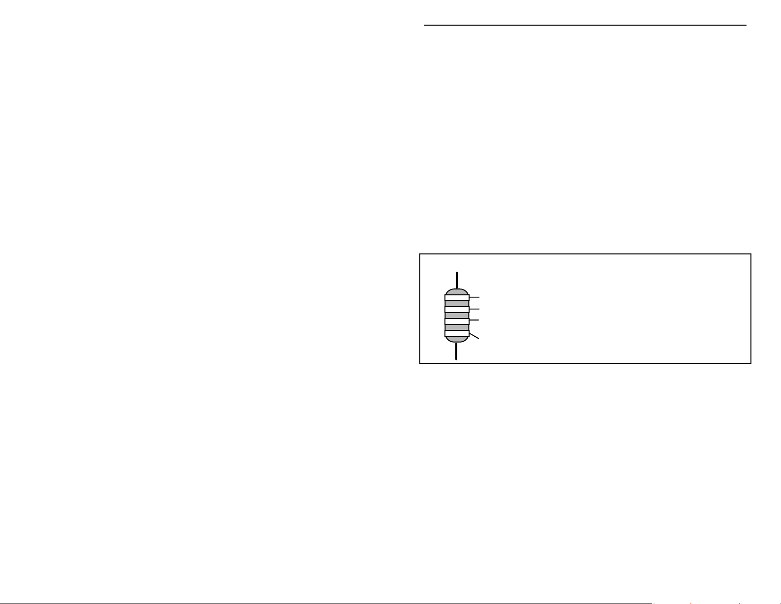
Sorting and Reading Resistors: The electrical value of resistors is indicated by
a color code (shown below). You don't have to memorize this code to work with
resistors, but you do need to understand how it works:
Resistor Color Code
Black = 0 (tens)
1st Digit
2nd Digit
Multiplier
Tolerence
(gold or silver)
When you look at a resistor, check its multiplier code first. Any resistor with a
black multiplier band falls between 10 and 99 ohms in value. Brown designates
a value between 100 and 999 ohms. Red indicates a value from 1000 to 9999
ohms, which is also expressed as 1.0K to 9.9K. An orange multiplier band
designates 10K to 99K, etc. To inventory resistors, first separate them into
groups by multiplier band (make a pile of 10s, 100s, Ks, 10Ks, etc.). Next, sort
each group by specific value (1K, 2.2K, 4.7K, etc). This procedure makes the
inventory easier, and also makes locating specific parts more convenient later on
during construction. Some builders find it especially helpful to arrange resistors
in ascending order along a strip of double-sided tape.
Reading Capacitors: Unlike resistors, capacitors no longer use a color code for
value identification. Instead, the value, or a 3-number code, is printed on the
body.
Brown = 1 (hundreds)
Red = 2 (K)
Orange = 3 (10K)
Yellow = 4 (100K)
Green = 5 (1Meg)
Blue = 6
Violet = 7
Gray = 8
White = 9
Silver = 10%
Gold = 5%
3
Page 4
VEC-4001K Owner’s Manual Professional Function Generator
Value Code
10 pF = 100
100 pF = 101
1000 pF = 102
.001 uF = 102*
.01 uF = 103
.1 uF = 104
As with resistors, it's helpful to sort capacitors by type, and then to arrange them
in ascending order of value. Small-value capacitors are characterized in pF (or
pico-Farads), while larger values are labeled in uF (or micro-Farads). The
transition from pF to uF occurs at 1000 pF (or .001 uF)*. Today, most
monolithic and disc-ceramic capacitors are marked with a three-number code.
The first two digits indicate a numerical value, while the last digit indicates a
multiplier (same as resistors).
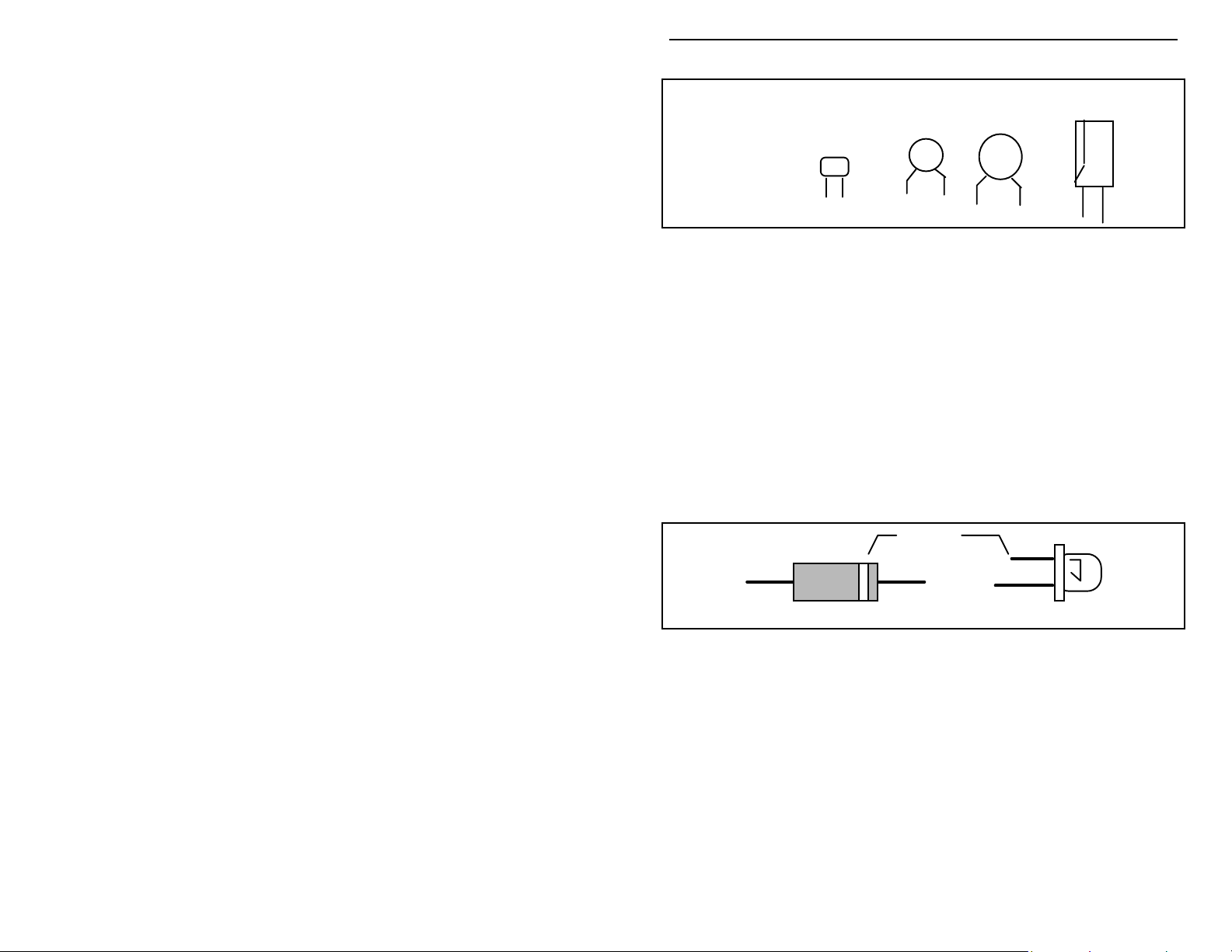
Electrolytic capacitors are always marked in uF. Electrolytics are polarized
devices and must be oriented correctly during installation. If you become
confused by markings on the case, remember the uncut negative lead is slightly
shorter than the positive lead.
Diodes: Diodes are also polarized devices that must be installed correctly.
Always look for the banded--or cathode--end when installing, and follow
instructions carefully.
Multilayer
(270 pF)
271
Ceramic Discs
(.001 uF) (.1 uF)
102
Cathode
104
Electrolytic
1 uF
|
1uF
|
35V
+
-
(shorter Lead)
Diode
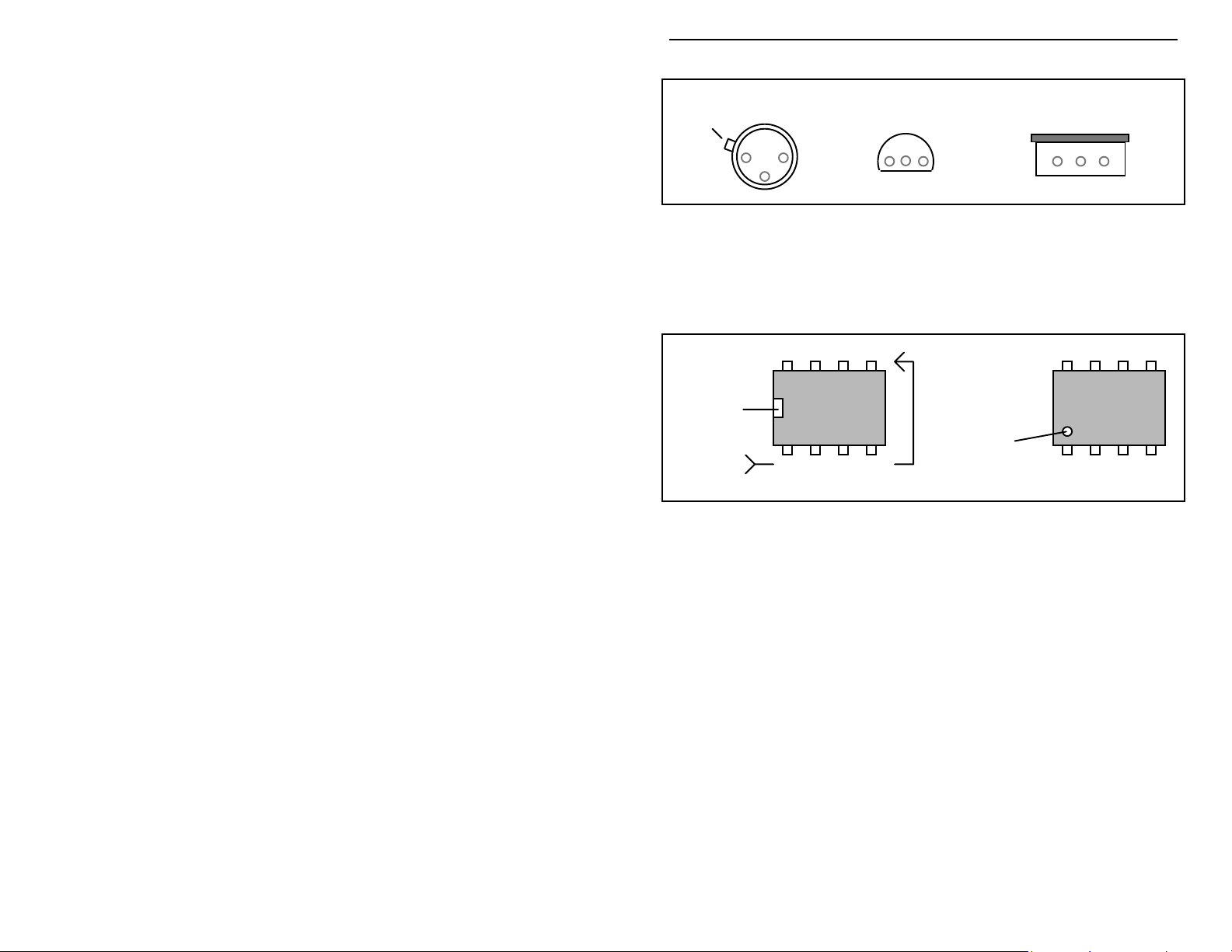
Transistors: If transistors are installed incorrectly, damage may result when
power is applied. Transistors in metal cases have a small tab near the emitter
lead to identify correct positioning. Semiconductors housed in small plastic
cases (TO-92) have an easily-identified flat side to identify mounting orientation.
Many specialized diodes and low-current voltage regulators also use this type
packaging. Larger plastic transistors and voltage regulators use a case backed
with a prominent metal tab to dissipate heat (T-220). Here, orientation is
indicated by the positioning of the cooling tab.
4
LED
Page 5
VEC-4001K Owner’s Manual Professional Function Generator
Metal Can Device Plastic Device Tab-cooled Device
Emitter
Flat Side
Integrated Circuits: Proper IC positioning is indicated by a dot or square
marking located on one end of the device. A corresponding mark will be silkscreened on the PC board and printed on the kit's parts-placement diagram. To
identify specific IC pin numbers for testing purposes, see the following diagram.
Pin numbers always start at the keyed end of the case and progress counterclockwise around the device, as shown:
8 7 6 5
Installation
Key
Installation
Key
1 2 3 4
Pin Numbers
Metal Tab
5
Page 6

VEC-4001K Owner’s Manual Professional Function Generator
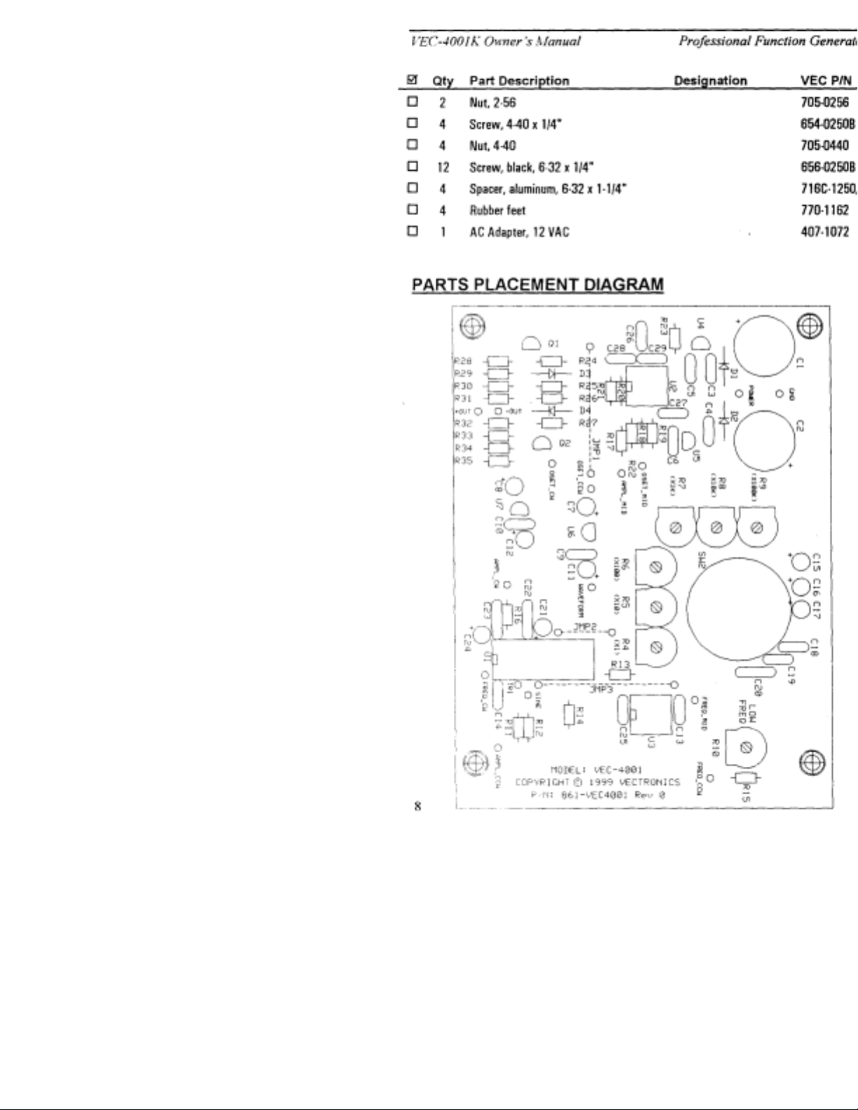
PARTS LIST
Your kit should contain all of the parts listed below. Please identify and
inventory each item on the checklist before you start building. If any parts are
missing or damaged, refer to the manual's warranty section for replacement
instructions. If you can't positively identify an unfamiliar item on the basis of the
information given, set it aside until all other items are checked off. You may
then be able to identify it by process of elimination. Finally, your kit will go
together more smoothly if parts are organized by type and arranged by value
ahead of time. Use this inventory as an opportunity to sort and arrange parts so
you can identify and find them quickly.
""""
Qty Part Description Designation VEC P/N
!
1 51 ohm resistor
(green-brown-black)
!
2 100 ohm resistor
(brown-black-brown)
!
1 680 ohm resistor
(blue-gray-brown)
!
1 1K resistor (brown-
black-red)
!
8 1.6K resistor (brown-
blue-red)
!
1 2K resistor (red-
black-red)
!
2 3K resistor (orange-
black-red)
!
4 12K resistor (brown-
red-orange)
!
2 22K resistor (red-red-
orange)
!
1 24K resistor (red-
yellow-orange)
!
2 27K resistor (red-
violet-orange)
!
1 1K trimpot (102) R10 133-3100
!
6 5K trimpot (502) R4-R9 133-3500
!
3 10K 24-mm
potentiometer (103)
R16 100-1510
R25,R26 100-2100
R15 100-2680
R19 100-3100
R28-R35 100-3160
R17 100-3200
R13,R21 100-330
R11,R12,R14,R
100-4120
20
R24,R27 100-4220
R18 100-4240
R22,R23 100-4270
R1,R2,R3 162-4100-
1
6
Page 7

VEC-4001K Owner’s Manual Professional Function Generator
!
1 680 pF disc ceramic
capacitor (681)
!
2
.001 µF disc ceramic
C20 200-0680-
1
C22,C23 200-1100
capacitor (102)
!
13
.1 µF disc ceramic
capacitor (104)
C3,C4,C5,C6,C
9,C10,C13,C14
200-3100
,C25,C26,
C27,C28,C29
!
1
.0068 µF polyester
C19 230-1680
ceramic capacitor
!
1
.082 µF polyester
C18 230-2820
ceramic capacitor
!
2
1 µF tantalum
capacitor
!
1
1 µF electrolytic
capacitor
""""
Qty Part Description Designation VEC P/N
!
1
10 µF electrolytic
capacitor
!
5
100 µF electrolytic
capacitor
!
2
2200 µF electrolytic
capacitor
!
2 1N4148 switching diode D3,D4 300-4148
!
2 1N4007 rectifier diode D1,D2 300-4007
!
1 2N3904 npn transistor Q1 305-3904
!
1 2N3906 pnp transistor Q2 305-3906
!
1 78L05 voltage
C21,C24 272-4100-
1
C17 270-4100-
2
C16 270-5100-
1
C7,C8,C11,C12
,C15
270-61001
C1,C2 270-7220-
1
U6 307-7805L
regulator IC
!
1 78L12 voltage
U4 307-7812L
regulator IC
!
1 79L05 voltage
U7 307-7905L
regulator IC
!
1 79L12 voltage
U5 307-79L12
regulator IC
!
1 LM318 op-amp U2 324-0318
7
Page 8

VEC-4001K Owner’s Manual Professional Function Generator
!
1 LM358 dual op-amp U3 324-0358
!
1 MAX038CPP function
U1 325-0038
generator IC
!
1 Six-position rotary
SW2 500-1008
switch
!
1 2P2T slide switch SW1 501-1003
!
1 4P4T slide switch SW3 501-1043
!
1 2.1-mm coaxial power
J1 601-6121
jack
!
1 Binding post, red J2 606-0003
!
1 Binding post, black J3 606-0004
!
2 IC socket, 8 pin 625-0008
!
1 IC socket, 20 pin 625-0020
!
1 Switch-style knob 760-0036
!
3 Control knob 760-0033
!
6 6" hook-up wire, black 871-2422-
0600
!
6 6" hook-up wire, red 871-2422-
0600
!
5 6" hook-up wire,
yellow
!
1 PC board, single-sided 861-
871-2444-
0600
VEC4001
!
1 Instruction manual 925-
VEC4001K
!
1 Case, plastic 840-0524
!
1 Faceplate, VEC-4001 804-
VEC4001
!
2 Screw, 2-56 x 3/8" 652-0375
""""
Qty Part Description Designation VEC P/N
!
2 Nut, 2-56 705-0256
!
4 Screw, 4-40 x 1/4" 654-0250B
!
4 Nut, 4-40 705-0440
!
12 Screw, black, 6-32 x
656-0250B
1/4"
8
Page 9
Page 10

VEC-4001K Owner’s Manual Professional Function Generator
STEP-BY-STEP CONSTRUCTION
In these instructions, when you see the term install, this means to locate, identify,
and insert the part into its mounting holes on the PC board. T his includes prebending or straightening leads as needed so force is not required to seat the part.
Once a component is mounted, bend each lead over to hold it in place. Use
sharp side-cutters to clip off excess lead length before soldering. Make sure
trimmed leads don't touch other pads and tracks, or a short circuit may result:
Good
Not Good
The term solder means to solder the part's leads in place, and to inspect both (or
all) solder connections for flaws or solder bridges. Nip off excess protruding
leads with a sharp pair of side cutters.
This kit has 25 fixed-value resistors. Mount these now, starting with the smallest
value and moving to the largest. Before mounting each one, carefully bend both
leads close to the resistor body to form right-angles, as shown below:
.4"
! ! 1.#Find a 51 Ohm resistor (green-brown-black). Install at R16 and
solder.
Locate two (2) 100 Ohm resistors (brown-black-brown).
! ! 2.#Install a 100 Ohms at R25 and solder.
! ! 3.#Install a 100 Ohms at R26 and solder.
! ! 4.#Find a 680 Ohm resistor (blue-gray-brown). Install at R15 and
solder.
! ! 5.#Find a 1K resistor (brown-black-red). Install at R19 and solder.
Locate eight (8) 1.6K resistors (brown-blue-red).
! ! 6.#Install a 1.6K at R28 and solder.
! ! 7.#Install a 1.6K at R29 and solder.
! ! 8.#Install a 1.6K at R30 and solder.
10
Page 11

VEC-4001K Owner’s Manual Professional Function Generator
! ! 9.#Install a 1.6K at R31 and solder.
! ! 10.#Install a 1.6K at R32 and solder.
! ! 11.#Install a 1.6K at R33 and solder.
! ! 12.#Install a 1.6K at R34 and solder.
! ! 13.#Install a 1.6K at R35 and solder.
! ! 14.#Find a 2K resistor (red-black-red). Install at R17 and solder.
Locate two (2) 3K resistors (orange-black-red).
! ! 15.#Install a 3K at R13 and solder.
! ! 16.#Install a 3K at R21 and solder.
Locate four (4) 12K resistors (brown-red-orange).
! ! 17.#Install a 12K at R11 and solder.
! ! 18.#Install a 12K at R12 and solder.
! ! 19.#Install a 12K at R14 and solder.
! ! 20.#Install a 12K at R20 and solder.
Locate two (2) 22K resistors (red-red-orange).
! ! 21.#Install a 22K at R24 and solder.
! ! 22.#Install a 22K at R27 and solder.
! ! 23.#Find a 24K resistor (red-yellow-orange). Install at R18 and solder.
Locate two (2) 27K resistors (red-violet-orange).
! ! 24.#Install a 27K at R22 and solder.
! ! 25.#Install a 27K at R23 and solder.
This completes installation of the 25 fixed-value resistors (trimpots and
potentiometers will be installed later). Take a moment to confirm each fixedvalue resistor is positioned in the right location on the PC board.
Next, we’ll install the kit’s diodes. . Diodes are polarized and must be oriented
correctly in order to work. T he banded end of the diode should align with the
single-lined end of the diode symbol on the PC board (see following diagram).
11
Page 12

VEC-4001K Owner’s Manual Professional Function Generator
Locate two (2) 1N4007 diodes.
! ! 26.#Install a 1N4007 at D1 and solder.
! ! 27.#Install a 1N4007 at D2 and solder.
Locate two (2) 1N4148 diodes.
! ! 28.#Install a 1N4148 at D3 and solder.
! ! 29.#Install a 1N4148 at D4 and solder.
Next, we'll install the kit's capacitors--starting with the disc-ceramic types.
! ! 30.#Find a 680 pF disc ceramic capacitor (681). Install at C20 and
solder.
Locate two (2) .001 µF disc ceramic capacitors (102).
! ! 31.#Install a .001 µF at C22 and solder.
! ! 32.#Install a .001 µF at C23 and solder.
Locate thirteen (13) .1 µF disc ceramic capacitors.
! ! 33.#Install a .1 µF at C3 and solder.
! ! 34.#Install a .1 µF at C4 and solder.
! ! 35.#Install a .1 µF at C5 and solder.
! ! 36.#Install a .1 µF at C6 and solder.
! ! 37.#Install a .1 µF at C9 and solder.
! ! 38.#Install a .1 µF at C10 and solder.
! ! 39.#Install a .1 µF at C13 and solder.
! ! 40.#Install a .1 µF at C14 and solder.
! ! 41.#Install a .1 µF at C25 and solder.
! ! 42.#Install a .1 µF at C26 and solder.
! ! 43.#Install a .1 µF at C27 and solder.
! ! 44.#Install a .1 µF at C28 and solder.
! ! 45.#Install a .1 µF at C29 and solder.
! ! 46.#Find the .0068 µF polyester ceramic capacitor (green, marked 682).
Install at C19 and solder.
12
Page 13

VEC-4001K Owner’s Manual Professional Function Generator
! ! 47.#Find the .082 µF polyester ceramic capacitor (green, marked .082).
Install at C18 and solder.
The last group of capacitors in your kit are electrolytic. Electrolytic caps are
polarized and must be installed the correct way in order to work. Each
capacitor's plus (+) mounting hole is marked on both the circuit board and parts
placement diagram. If the markings on the capacitor body are unclear, the plus
(+) lead is always the longer of the two. Most polarized caps you'll install are
aluminum-encased electrolytics. However, your kit also contains two
specialized 1 µF electrolytics called tantalum capacitors. These are small
bulbous parts with a tan-colored dipped-epoxy coating. Do not confuse these
with the 1 µF aluminum type electrolytic also supplied in the kit.
Tantalum Electrolytic Aluminum Electrolytic
+
+
Find the two (2) 1 µF tantalum caps (marked 1 µD). Identify the longer plus
lead (marked +).
! ! 48.#Observing polarity, install a 1 µF tantalum cap at C21.
! ! 49.#Observing polarity, install a 1 µF tantalum cap at C24.
The remaining polarized caps are standard aluminum-case electrolytics.
! ! 50. Locate a 1 µF electrolytic. Observing polarity, install at C17 and
solder.
! ! 51. Locate a 10 µF electrolytic. Observing polarity, install at C16 and
solder.
Find five (5) 100 µF electrolytics. Observing polarity, install as follows:
! ! 52. Install a 100 µF at C7 and solder.
! ! 53. Install a 100 µF at C8 and solder.
! ! 54. Install a 100 µF at C11 and solder.
! ! 55. Install a 100 µF at C12 and solder.
! ! 56. Install a 100 µF at C15 and solder.
Find two (2) 2200 µF electrolytics. Observing polarity:
13
Page 14

VEC-4001K Owner’s Manual Professional Function Generator
! ! 57. Install a 2200 µF at C1 and solder.
! ! 58. Install a 2200 µF at C2 and solder.
This completes installation of all capacitors. Before moving on construction, recheck the polarity of each electrolytic one more time to confirm all are installed
correctly.
The first group of semiconductor include four (4) small ICs and two (2)
transistors. These are all packaged exactly alike. To avoid confusion, read
markings carefully before installing! Like the electrolytic caps, transistors and
ICs must be oriented correctly to work.
Transistors Voltage Regulators
78L05
2N3904
2N3906
78L12
79L05
79L12
! ! 59. Find a 78L05 voltage regulator IC. Install at U6 and solder.
! ! 60. Find a 78L12 voltage regulator IC. Install at U4 and solder.
! ! 61. Find a 79L05 voltage regulator IC. Install at U7 and solder.
! ! 62. Find a 79L12 voltage regulator IC. Install at U5 and solder.
! ! 63. Find a 2N3904 transistor. Install at Q1 and solder.
! ! 64. Find a 2N3906 transistor. Install at Q2 and solder.
The remaining ICs will be installed in sockets. Locate the two (2) eight-pin IC
sockets and one (1) 20-pin socket provided. Identify the notch (or key) at one
end. During installation, each socket will be oriented so that this notch
corresponds to the key on the PC layout.
Key
When installing sockets, make sure all pins enter the mounting holes and appear
on the opposite side of the PC board (it's easy to fold them under the socket).
Also, when soldering, make sure the socket remains flush with the board surface.
14
Page 15
VEC-4001K Owner’s Manual Professional Function Generator
! ! 65. Find a eight-pin IC socket. Orient to U2, install, and solder all 8
pins.
! ! 66. Find a eight-pin IC socket. Orient to U3, install, and solder all 8
pins.
! ! 67. Find a twenty-pin IC socket. Orient to U1. install, and solder all 20
pins.
The ICs will be installed later.
Your kit contains seven (7) calibration trimpots. Locate these now. From this
group, identify the 1K trimpot (marked 1K or 102). This will be installed first.
All others are 5K (marked 5K or 502). Make sure the trimpot body is flush
against the PC board before soldering in place.
! ! 68. Install a 1K trimpot at R10 and solder.
! ! 69. Install a 5K trimpot at R4 and solder.
! ! 70. Install a 5K trimpot at R5 and solder.
! ! 71. Install a 5K trimpot at R6 and solder.
! ! 72. Install a 5K trimpot at R7 and solder.
! ! 73. Install a 5K trimpot at R8 and solder.
! ! 74. Install a 5K trimpot at R9 and solder.
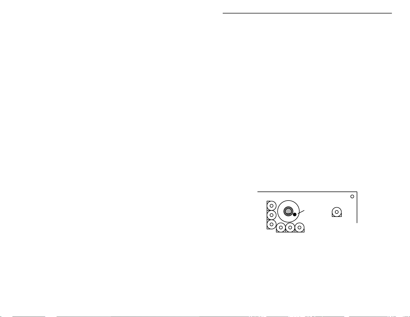
Find the 6-position rotary switch. Orient at SW2, as shown below--noting the
raised "key" next to the shaft.
Switch
Key
The switch must be seated firmly before soldering to ensure shaft alignment with
the front panel.
! ! 75. Install the 6-position rotary switch at SW2 and solder all pins in
place.
Three insulated jumpers are needed to complete PC board assembly. To
prepare, cut hook-up wire to the prescribed length and strip 1/4" of insulation
from both ends. Find a 6" length of yellow hook-up wire and cut as follows:
15
Page 16

VEC-4001K Owner’s Manual Professional Function Generator
! ! 76. Cut to 1 3/4" and prepare jumper. Install at JMP3 and solder.
! ! 77. Cut to 1 3/4" and prepare jumper. Install at JMP1 and solder.
! ! 78. Cut to 1" and prepare jumper. Install at JMP2 and solder.
Finally, locate the remaining three (3) ICs. Each has a round key or a notch at
one end to indicate correct orientation. Before installing, inspect carefully and
confirm all pins are straight. During installation, align pins carefully and insert
slowly to avoid bending or folding. Observing orientation, install as follows:
! ! 79. Install the LM318 op-amp IC at U2.
! ! 80. Install the LM358 op-amp IC at U3.
! ! 81. Install the MAX038CPP function-generator IC at U1.
All components should now be installed on your PC board. Next, you'll install
switches, controls, and jacks on the front panel and wire them to the PC board.
Before starting this procedure, give the PC board a thor ough inspection.
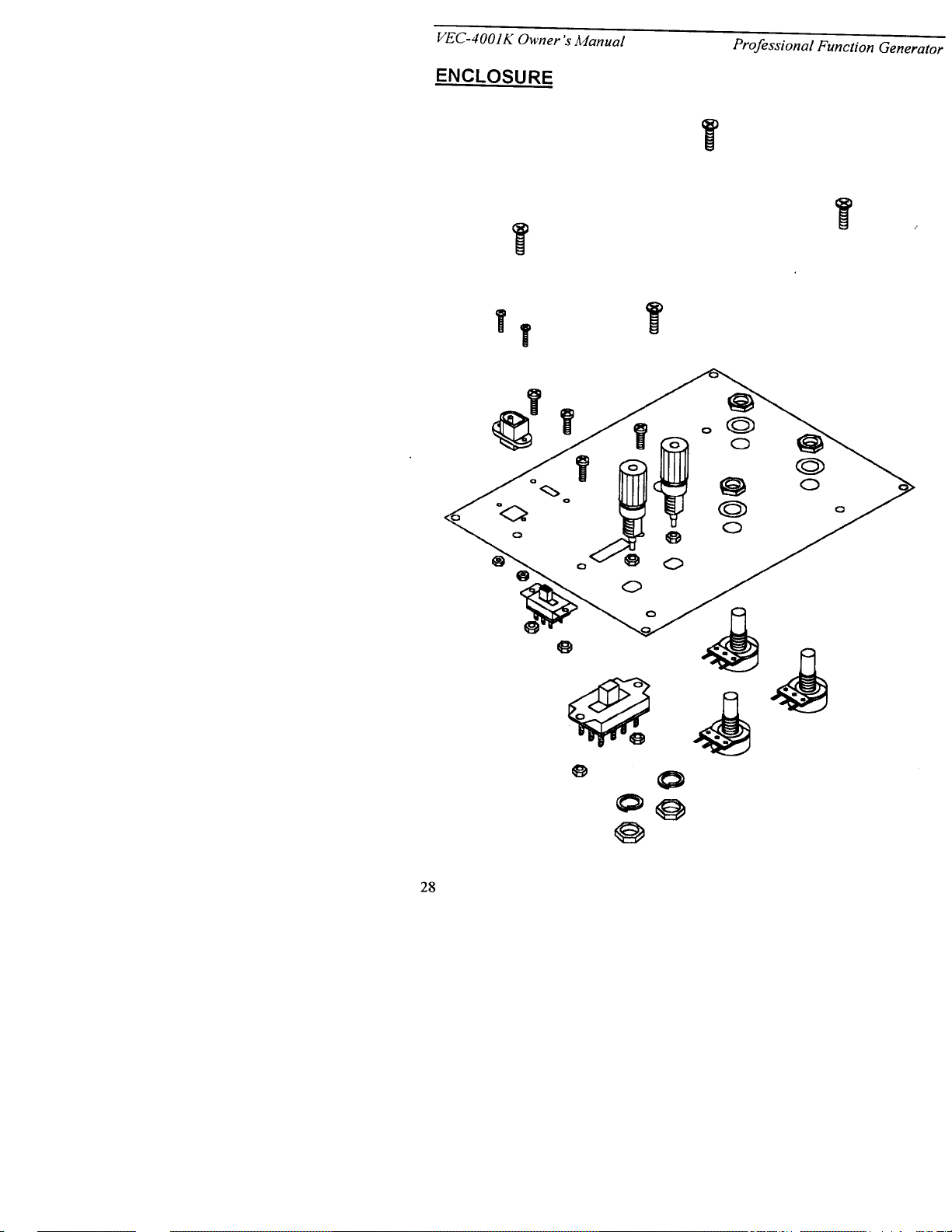
This is the final phase of construction. To begin, position the front panel with
the silk-screened side down, as shown below. Locate the remaining switches,
jacks, and potentiometers. Install as follows:
Black binding post
J3
Red binding post
J2
R3
R2
10K pot
10K pot
R1
Spacer
6-32
Spacer
6-32
4-40
4P3T Switch SW3
2-56
Power Jack
J1
10K pot
2P2T Switch
SW1
4-40
Find two (2) binding posts. When installing, use care not to overtighten--plastic
threads may be damaged by excessive torque.
! ! 82. Install the black binding post at J3.
! ! 83. Install the red binding post at J2.
16
Page 17

VEC-4001K Owner’s Manual Professional Function Generator
Locate three (3) 10K pots (marked B103 or B10K). Using a flat washer and a
nut, install each at the position indicated. Orient with solder terminals to the left
side:
! ! 84. Install a 10K pot at R1.
! ! 85. Install a 10K pot at R2.
! ! 86. Install a 10K pot at R3.
! ! 87. Find the 4P3P slide switch. Using 4-40 hardware, install at SW3.
! ! 88. Find the 2P2T slide switch. Using 4-40 hardware, install at SW1.
! ! 89. Find the 2.1-mm power jack. Position as shown, with the larger
riveted (+) terminal at the bottom. Using 2-56 hardware, install at J1
from the front side of the panel.
Locate four (4) 1-1/4" aluminum spacers. Using 6-32 screws, install on the front
panel at the positions shown:
! ! 90. Install a spacer above J3.
! ! 91. Install a spacer next to J1.
! ! 92. Install a spacer below R1.
! ! 93. Install a spacer above R2.
This concludes mounting of front-panel components. Double-check to make
sure each is positioned correctly. Begin wiring by installing a short jumper
between the power jack and power switch. Find a length of yellow wire and
prepare as follows:
! ! 94. Cut a 1 1/2" length of yellow wire. Remove 1/4" insulation from one
end and 3/8" insulation from the other.
! ! 95. Thread the stripped 3/8" end through the bottom two terminals of
SW1, as shown in the following diagram. Solder to both pins.
! ! 96. Connect the other end to the riveted (+) terminal of power jack J1
and solder (see followingdiagram).
17
Page 18

VEC-4001K Owner’s Manual Professional Function Generator
Color Code
J3 J2
SW3
R3
R2
Red
Yellow
Black
Top or "cl ockwise"
terminal (CW).
Middle or "center"
terminal (CTR)
Bottom or "cou nter-clockwise"
terminal (CCW)
J1
R1
SW1
The remaining wires will be installed one control at a time, and twisted together
for routing to the PC board. To prepare, cut each to the specified length and
remove 1/4" insulation from each end. Wrap tab or lug connections before
soldering (see following diagram):
Tab
Lug
! ! 97. Begin by wiring R1. Cut and prep a set of 6" red, yellow, and black
lead. Find R1 and install as follows:
! ! 98. Attach a red lead to the top (CW) terminal of R1 and solder.
! ! 99. Attach a yellow lead to the center (CTR) terminal of R1 and solder.
! ! 100. Attach a black lead to the bottom (CCW) terminal of R1 and solder.
! ! 101. Twist all three wires together, leaving about 1 1/2" unwound at the
far end.
! ! 102. Cut and prep another set of 6" wires (red, yellow, and black). Find
R2.
! ! 103. Attach a red lead to the top (CW) terminal of R2 and solder.
! ! 104. Attach a yellow lead to the center (CTR) terminal of R2 and solder.
! ! 105. Attach a black lead to the bottom (CCW) terminal of R2 and solder.
! ! 106. Twist all three wires together, leaving about 1 1/2" unwound at the
far end.
18
Page 19

VEC-4001K Owner’s Manual Professional Function Generator
! ! 107. Cut and prep another set of 6" wires (red, yellow, and black). Find
R3.
! ! 108. Attach a red lead to the top (CW) terminal of R3 and solder.
! ! 109. Attach a yellow lead to the center (CTR) terminal of R3 and solder.
! ! 110. Attach a black lead to the bottom (CCW) terminal of R3 and solder.
! ! 111. Twist all three wires together, leaving about 1 1/2" unwound at the
far end.
! ! 112. Cut and prep a 6" red and black lead. Find binding posts J2, J3.
! ! 113. Connect the red wire to J2 and solder.
! ! 114. Connect the black wire to J3 and solder.
! ! 115. Twist together.
! ! 116. Cut and prep a 6" red, yellow, and black lead. Find SW3 and locate
the lower right-hand terminal (see diagram).
! ! 117. Attach a black lead on the bottom right-hand terminal and solder.
! ! 118. Move left one terminal and attach a red lead. Solder.
! ! 119. Move left again, and attach a yellow lead. Solder.
! ! 120. All three leads should be connected on the bottom row. Twist wires
together.
! ! 121. Cut a 6" red and black lead. Remove 1/4" insulation from one end
and 3/8" insulation from the other end on each.
! ! 122. T hread the 3/8" end of the black lead through the two free terminals
on J1. Solder.
! ! 123. Thread the 3/8" end of the red wire through the center terminals o n
SW1. Solder.
! ! 124. Twist both together.
This completes front-panel wiring. Check your work against the wiring pictorial
for errors. The next group of connections will be made on the PC board.
Locate the three-wire harness connected to Frequency control R1. Connect to
the PC board as follows:
! ! 125. Connect R1 red wire to FREQ_CW (near key end of U1).
! ! 126. Connect R1 yellow wire to FREQ_MID (near unkeyed end of U3).
! ! 127. Connect R1 black wire to FREQ_CCW (near R10).
19
Page 20

VEC-4001K Owner’s Manual Professional Function Generator
Locate the three-wire harness connected to Amplitude control R2.
! ! 128. Connect R2 red wire to AMPL_CW (near R16).
! ! 129. Connect R2 yellow wire to AMPL_MID (near R17).
! ! 130. Connect R2 black wire to AMPL_CCW (near R11).
Locate the three-wire harness connected to DC Offset control R3.
! ! 131. Connect R3 red wire to OSET_CW (near Q2).
! ! 132. Connect R3 yellow wire to OSET_MID (near R18).
! ! 133. Connect R3 black wire to OSET_CCW (near end of JMP1).
Locate the three-wire harness connected to Waveform switch SW3.
! ! 134. Connect SW3 red wire to WAVEFORM (near C11).
! ! 135. Connect SW3 yellow wire to TRI (near R11).
! ! 136. Connect SW3 black wire to SINE (near R12).
Locate the two-wire pair connected to On/Off switch SW1 and 12VAC jack J1.
! ! 137. Connect SW1/J1 red wire to POWER (between C1 and C2).
! ! 138. Connect SW1/J1 black wire to GND (same).
Finally, locate the two-wire pair connected to Output binding posts J2, J3.
! ! 139. Connect J2 red wire to +OUT (between R31 and R32).
! ! 140. Connect J3 black wire to -OUT (same).
This concludes wiring of your VEC-4001K Function Generator Kit. Before
moving on to the next section, give your kit a thorough QC (quality control)
inspection. This will help you discover any inadvertent assembly errors that
might prevent the unit from working or cause damage to parts. Follow this
procedure:
1. Compare parts locations with the parts-placement diagram. Was each part
installed where it is supposed to be? Was the correct value used? Start at
one side of the board and work your way across in an organized pattern.
2. Inspect the solder side of the board for cold-solder joins and solder bridges
between tracks or pads. Use a magnifying glass to obtain a clear view of the
track area. If you suspect a solder bridge, hold the board in front of a bright
light for a better view. All joints should be smooth and shiny, indicating
good solder wetting and flow. Resolder any beaded or dull-appearing
connections. Also, check the front-panel jacks, switches, and connectors for
defective solder connections.
20
Page 21

VEC-4001K Owner’s Manual Professional Function Generator
3. Finally, check electrolytic capacitors and diodes for correct polarity. Does
the plus (+) polarity symbol on the part agree with the pictorial and with the
pattern on the PC board? Is the banded end of each diode positioned
correctly? Were all ICs and transistors installed correctly?
Be sure to correct all errors before moving on.
TESTING AND ALIGNMENT
Before applying power and testing, mount the circuit board and install the unit's
control knobs:
! Orient the PC board so the shaft of Multiplier switch SW2 aligns with its
panel opening. Align mounting holes with the aluminum spacers. Secure
the PC board in place using four (4) 6-32 screws.
! Find three (3) 3/4" skirted knobs. Install these on the Frequency, DC Offset,
and Amplitude controls.
!#Find the 3/4" pointer knob. Install on the Multiplier control.
Note
: If you want the pointer knob even with the skirted knobs, simply trim
1/8” off the Multiplier control shaft before installing the pointer knob. This
can be done using large or heavy duty cutters on the plastic shaft.
Power-Up: Your unit is d esigned to run from 12 VAC only and will not work
with conventional 12 VDC power sources. Use only the wall-adapter
transformer supp lied or an equival ent AC source. Before pluggi ng in the power
adapter, position the Generator's On/Off switch to "off".
To check the internal power supply circuitry, connect a DVM to the Output posts
observing (+) and (-) polarity. Set meter for the 10 VDC range. Position DC
Offset and Frequency at 12:00 o'clock. Set Multiplier for 10
2
. Turn Amplitude
fully down (counter-clockwise). Waveform setting isn't important for now.
Apply power by setting the Off/On switch to "on".
1. Rotate DC Offset to the (-) side. The DVM should read a progressively
stronger negative voltage down to -6 volts.
2. Rotate DC Offset toward (+). This should yield a corresponding positive
voltage up to +6 volts.
If you fail to obtain this result, re-check power supply circuitry around U4-U7
and note the orientation of U2 in its socket. Also, check Q1/Q2.
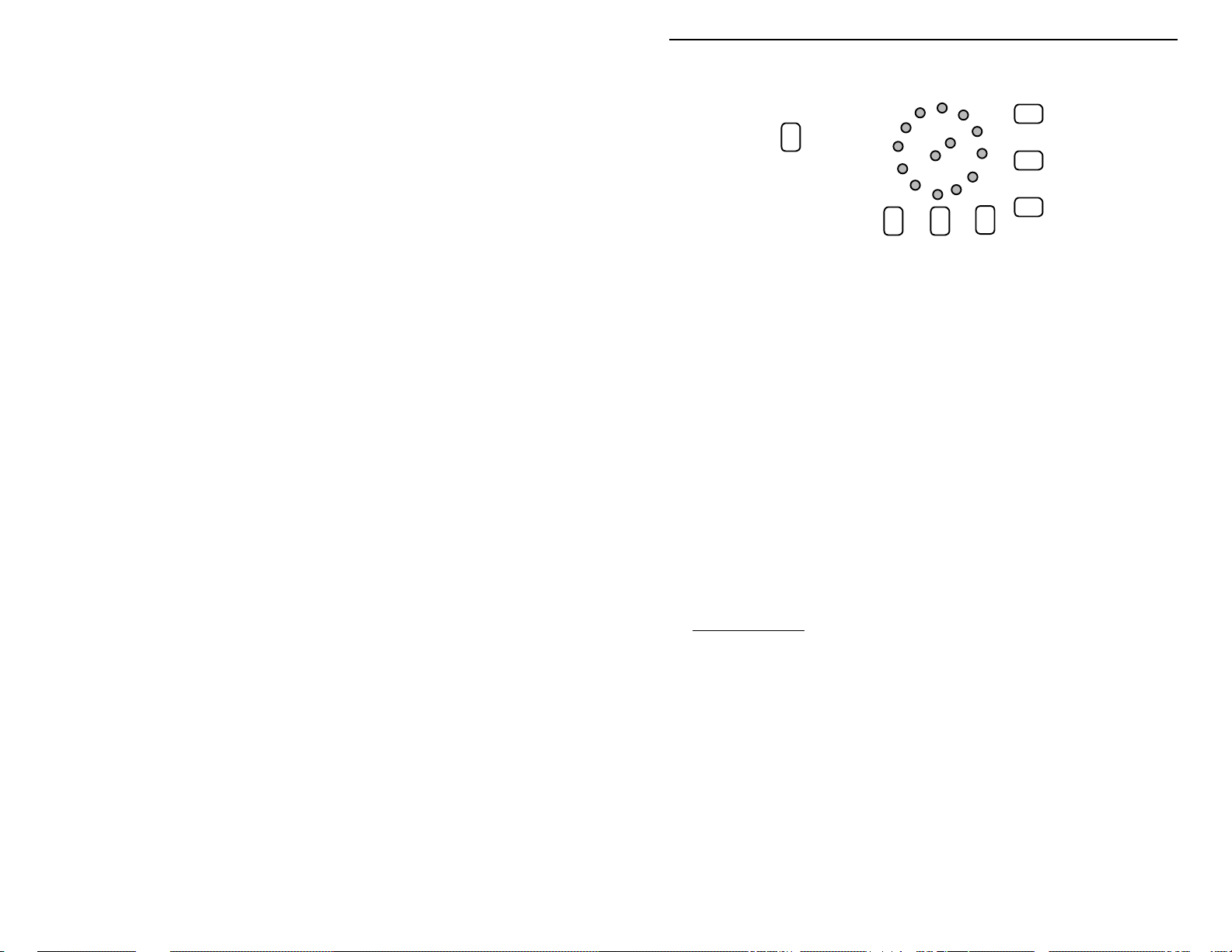
Waveform Check: Before conducting this check, adjust all internal calibration
trimpots (R4-R10) for midscale (12:00). These are all accessible through the
back side of the PC board, as shown.
21
Page 22
VEC-4001K Owner’s Manual Professional Function Generator
0
1
2
3104105
Bottom View
Low Set
R9
R10
R4 R5 R6
10
10
10
R8
R7
10
To check the generator's output signal, set an oscilloscope to measure 10 Vpp
with a 1 mS sweep rate. Connect scope input to Output. Set the generator's DC
Offset, Amplitude, and Frequency for 12:00, and switch Multiplier to 10
2
.
3. Set Waveform for sinewave and check output trace.
4. Set for triangle and check output trace.
5. Set for squarewave and check output trace.
6. Adjust Amplitude up and down observing change.
The generator's peak-to-pea k output should roughly coincide with scale markings
on the Amplitude control. If you fail to obtain the correct waveforms, check
switch wiring and PC-board connections. If amplitude is substantially
inaccurate, check for errors around R2.
Frequency Calibration: You may calibrate your generator using an audio
frequency counter or an oscilloscope with a calibrated sweep. Note that some
wide-range RF counters may not perform well at audio frequencies below 100
kHz.
A. Counter Method
: Connect counter to Output terminals. Set DC Offset and
Amplitude at 12:00. Set Frequency to 10 (CW) and Waveform to square.
1. Set Multiplier to 10
2. Switch Multiplier to 10
3. Switch Multiplier to 10
4. Switch Multiplier to 10
5. Switch Multiplier to 10
6. Switch Multiplier to 10
5
and adjust R9 for 1 MHz output.
4
and adjust R8 for 100 kHz output.
3
and adjust R7 for 10 kHz output.
2
and adjust R6 for 1 kHz output.
1
and adjust R5 for 100 Hz output.
0
and adjust R4 for 10 Hz output.*
7. Set Frequency control to 1 (CCW).
8. Switch Multiplier back to 10
2
and adjust R10 for 100 Hz output.
22
Page 23

VEC-4001K Owner’s Manual Professional Function Generator
* Note that counters designed for RF work may not read 10 Hz or even 100 Hz
with accuracy. If your counter has an input filter, it should be switched "on"
when measuring frequencies in this range.
B. Scope Method #1: Connect a scope with calibrated sweep to Output. Set
DC Offset and Amplitude for 12:00. Set Frequency to 10 (CW) and
Waveform to square. Trimpots will be adjusted to yield period of 5 divisions.
When adjusting the trimpots, make sure the waveform is symmetrical; that is,
the high transition time equals to the low transition time.
1. Set Multiplier to 1 0
5
and set Sweep for .2 µS/div. Adjust R9 for 5 division
period.
4
2. Switch Multiplier to 10
and set Sweep for 2 µS/div. Adjust R8 for 5 division
period.
3
3. Switch Multiplier to 10
and set Sweep for 20 µS/div. Adjust R7 for 5
division period.
4. Switch Multiplier to 10
2
and set Sweep for .2 mS/div. Adjust R6 for 5
division period.
5. Switch Multiplier to 10
1
and set Sweep for 2 mS/div. Adjust R5 for 5
division period.
6. Switch Multiplier to 10
0
and set Sweep for 20 mS/div. Adjust R4 for 5
division period.*
7. Set Frequency control to 1 (CCW).
8. Switch Multiplier back to 10
2
and Sweep for 2 mS/div. Adjust R10 for 5
division period.
* Note the period might be longer than 5 divisions due to component tolerance.
To compromise for this tolerance, adjust for longer than 5-division period
when adjusting trimpot R10 so the frequency ranges will overlapped.
C. Scope Method #2: Connect a scope with calibrated sweep to Output. Set
DC Offset and Amplitude for 12:00. Set Frequency to 10 (CW) and
Waveform to triangle. Trimpots will be adjusted to yield 1 Hz per division.
To ensure accuracy, each waveform peak should align with horizontal
divisions all the way across the screen (see the following diagram).
23
Page 24

VEC-4001K Owner’s Manual Professional Function Generator
1
2
3
4
5
Generator Range
100 1-10 Hz
10-100 Hz
10
100-1000 Hz
10
1 kHz - 10 kHz
10
10 kHz - 100 kHz
10
100 kHz - 1 MHz
10
1. Set Multiplier to 105 and set Sweep for 1 µS. Adjust R9 for 1 Hz/Div.
4
2. Switch Multiplier to 10
3. Switch Multiplier to 10
4. Switch Multiplier to 10
5. Switch Multiplier to 10
6. Switch Multiplier to 10
the entire screen (all 10 divisions).*
7. Set Frequency control to 1 (CCW).
8. Switch Multiplier back to 10
Hz/Div.
* Note 1 Hz might span longer than 10 divisions due to component tolerance. To
compromise for this to lerance, adjust for greater th an one division cycle when
adjusting trimpot R10 so the frequency ranges will overlapped.
and set Sweep for 10 µS. Adjust R8 for 1 Hz/Div.
3
and set Sweep for .1 mS. Adjust R7 for 1 Hz/Div.
2
and set Sweep for 1 mS. Adjust R6 for 1 Hz/Div.
1
and set Sweep for 10 mS. Adjust R5 for 1 Hz/Div.
0
and leave Sweep at 10 mS. Adjust R4 so 1 Hz spans
2
and leave Sweep at 10 mS. Adjust R10 for 1
This concludes calibration. If your generator fails to calibrate properly on one or
more Multiplier settings, check component values in the affected range(s) for
errors.
To complete your unit, install the the front panel (with the pc board attached) to
the plastic enclosure. Use the four (4) remaining 6-32 screws to secure the front
panel to the enclosure. Finally, place the four (4) rubber feet on the botton of the
enclosure. Place one at each corner.
24
Page 25

VEC-4001K Owner’s Manual Professional Function Generator
OPERATING INSTRUCTIONS
Control Functions: See the follwing diagram for control locations:
2
12 VAC
On
Professional Function Generator
1
Off
Power
34
7
Waveform
-+
Output
8
1. Power Adapter: Generator requires 12-VAC adapter (do not use DC types).
2. Power Switch: Turns power on and off.
3. Multiplier: Selects generator freq uency range as a power of 1 0 (1 Hz to 1
MHz).
4. Frequency: Varies frequency from 1 to 10 times the Multiplier setting.
5. Amplitude: Adjusts output amplitude from 0 to 12-volts p-p.
6. DC Offset: Adjusts DC bias on waveform from -6 to +6 VDC.
7. Waveform: Selects square, triangle, or sine waveform output.
8. Output: Bind ing posts provide connection to device under test.
To set for a given output signal, first select the desired increment using the
Frequency control. Then, set the desired Multiplier. For example, a Frequency
setting of 5 and a Multiplier of 10
is calibrated in volts p-p. To obtain low-level signals for AF amplifier testing,
install a 10:1 or 100:1 voltage divider across the output terminals using 1/4-watt
resistors. At low signal levels, the use of a shielded test cable is recommended.
Multiplier Frequency
6
DC Offset Amplitude
2
yields a 500-Hz (5 × 10²) signal. Amplitude
5
25
Page 26

VEC-4001K Owner’s Manual Professional Function Generator
IN CASE OF DIFFICULTY
If your VEC-4001K Generator fails to perform to your expectation, please try
these simple steps before seeking outside assistance. If you are still unable to
resolve the problem, technical assistance and repair services are available from
Vectronics (see warrantee for terms and conditions).
Unit won't power up: Check AC adapter. Also, check plug at Generator's
power jack--this must be 2.1-mm type to transfer power. AC wall adapter must
have 12-VAC output (DC adapters won't work). Check cable for breaks, etc.
No Output: Check cable from generator Output to DUT. Check U2 for
damage.
Hum on Output Signal: Open ground on test line. Also, ground loop on
bench. Make sure all test equipment and other power sources are tied to a
common ground.
Low Generator Output: Low-Z load or shorted test cable.
Distortion on Waveform: Low-Z load or short on output of generator. Also,
damage to U2 or incorrect components installed during construction.
If these checks fail to uncover the problem, repeat the "QC" check one more
time. Service records show that, for most malfunctioning kits, outright
component failure is relatively rare. In most cases, the culprit is a misplaced
part, reverse-polarized capacitor or diode, improperly installed transistor, or
faulty solder connection. If, despite your best effort, you cannot solve the
problem, kit repair services are ava ilable through Ve ctronics. See t he warranty
on the inside front cover for complete instructions.
26
Page 27

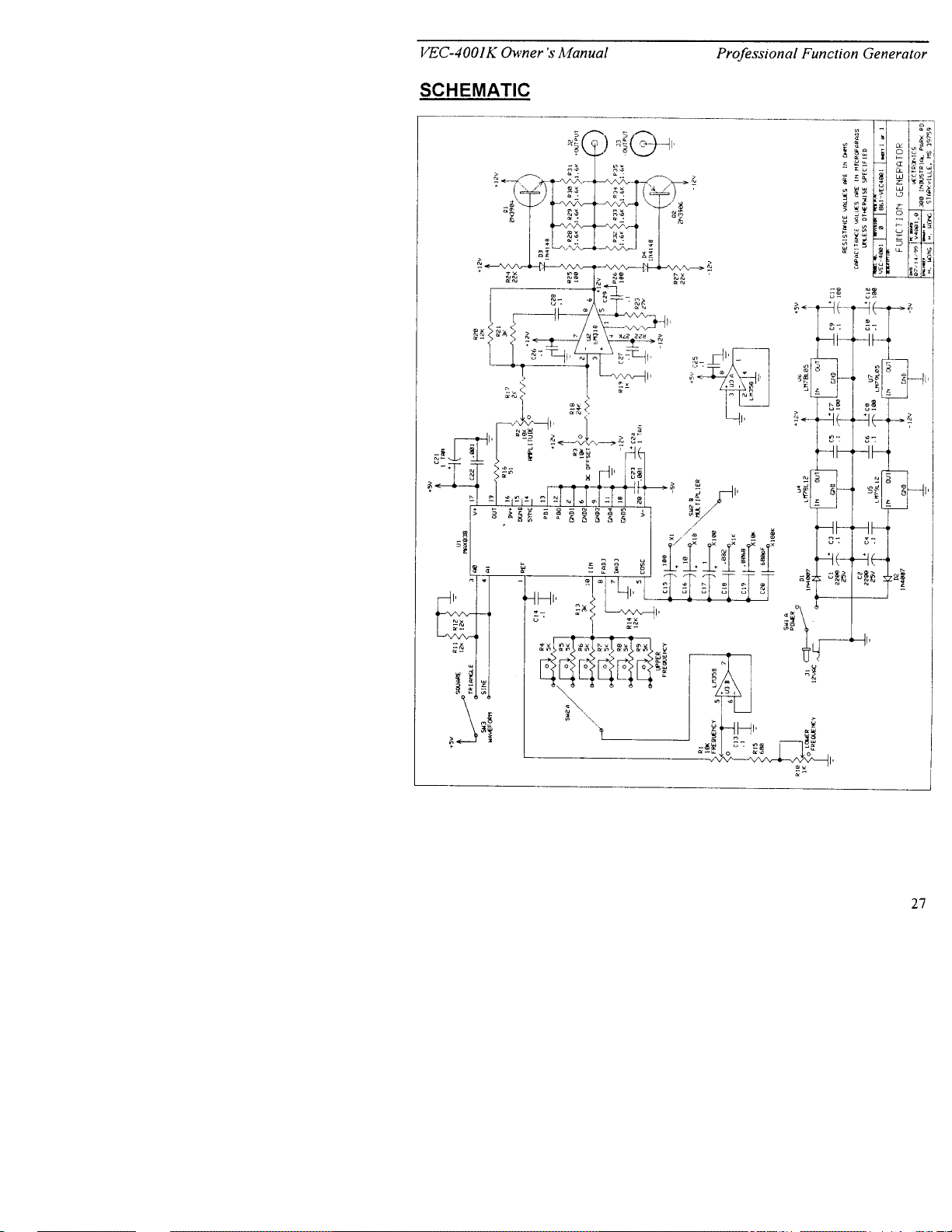
VEC-4001K Owner’s Manual Professional Function Generator
THEORY OF OPERATION AND SPECIFICATIONS
Your generator kit is built around the MAX038CPP, a special-function IC at U1
which provides sinewave, squarewave, and triangle-wave output over a wide
frequency range. Op-amp U2 buffers the generator IC's output signal and
establishes adjustable DC Offset. U3 buffers the IC's VCO reference voltage to
ensure stability. Q1/Q2 provide low-Z output with short-circuit protection. All
source voltages are regulated (U4-U7).
Typical Specifications:
Power Requirements:.......................12 VAC
Frequency Range:............................1 Hz to 1 MHz in six decade ranges
Amplitude Range:............................0 to 12 volts peak-to-peak
DC Offset Range:............................-6 volts to +6 volts
Output Impedance:..........................400 ohms, short-circuit protected
27
Page 28
Page 29
Page 30

 Loading...