

Page 1

IMPORTANT WARRANTY INFORMATION! PLEASE READ
Return Policy on Kits When Not Purchased Directly From Vectronics: Before continuing
any further with your VEC kit check with your Dealer about their return policy. If your Dealer
allows returns, your kit must be returned before you begin construction.
Return Policy on Kits When Purchased Directly From Vectronics: Your VEC kit may be
returned to the factory in its pre-assembled condition only. The reason for this stipulation is,
once you begin i nsta lli ng a nd sol deri ng pa rt s, you essenti al ly tak e over the rol e of the devic e's
manufacturer . From this point on, neither Vect ronics nor its dea lers can reas onably be held
accountab le for the qua lity or the outcome of your work. Because of this, Vectronics cannot
accept return of any kit-in-progress or completed work as a warranty item for any reason
whatsoever. If you are a new or inexperienced kit b uilder, we urge you to read the manual
carefully a nd determine whether or not you're r eady to tak e on the job. If you wish to c hange
your mind and return your ki t, you may--b ut you must do i t before you begin c ons tr uc ti on, a nd
within ten (10) working days of the time it arrives.
Vectronics Warrants: Your kit contains each item specified in the parts list.
Missing Parts: If you determine, during your pre-construction inventory, that any part is
missing, please contact Vectronics and we'll send the missing item to you free of charge.
However, before you contact Vect ronic s, please look carefully to c onf ir m you haven't misr ea d
the marking on one of the other items provided with the kit. Also, make certain an alternative
part hasn't been substituted for the item you're missing. If a specific part is no longer
available, or if Engineering has determined that an alternative component is more suitable,
Vectronics reserves the right to make substitutions at any time. In most cases, these changes
will be clearly noted in an addendum to the manual.
Defective Parts: Today's electronic parts are physically and electrically resilient, and
defective components a re r a re. However, if you disc over a n it em duri ng your pr e- c onst r uct i on
inventory that's obviously broken or unserviceable, we'll replace it. Just return the part to
Vectronics at the address below accompanied with an explanation. Upon receipt, we'll test it.
If it's defec tive and appear s unused, we'll ship you a new one right away at no charge.
Missing or Defective Parts After You Begin Assembly: Parts and materials lost or
damaged after construction begins are not covered under the terms of this warranty. However,
most parts supplied with VEC kits are relatively inexpensive and Vectronics can replace them
for a reasonable charge. Simply contact the factory with a complete description. We'll
process your order quickly and get you back on trac k.
Factory Repair After You Begin Assembly: Kits-in progress and completed kits are
specifically excluded from coverage by the Vectronics warranty. However, as a service to
customers, tec hnicia ns ar e availa ble t o evaluate a nd repai r malf unctioni ng kits for a minimum
service fee of $18.00 (½ hour rate) plus $7.00 shipping and handling (prices subject to
change). To qualify for repair service, your kit must be fully completed, unmodified, and the
printed circuit board assembled using rosin-core solder. In the event your repair will require
more than an hour to fi x (or $36.00, subject to change), our technicians will contact you in
advance by telephone b efore p erforming t he work. Def ective unit s should b e shipp ed prep aid
to:
Vectronics
1007 HWY 25 South
Starkville, MS 39759
Page 2

When shipping, pack your kit well and include the minimum payment plus shipping and
handling charges ($25.00 total). No work can be performed without pre-payment. Also,
provide a valid UPS return address a nd a day time phone number where you may be reac hed.
Page 3

Table of Contents
Introduction.....................................................................................................1
Tools and Supplies..........................................................................................1
Before You Start Building...............................................................................2
Parts List..........................................................................................................6
Parts Placement Diagram ................................................................................7
Step-By-Step Construction..............................................................................8
PC Board Inspection...............................................................................15
Testing and Alignment ....................................................................................15
Self Test..................................................................................................16
Operating Instructions.....................................................................................18
Special Functions....................................................................................21
Message Memory...................................................................................24
Morse Code Character Set......................................................................26
In Case of Difficulty........................................................................................27
Theory of Operation and Specifications..........................................................28
Circuit Description:................................................................................28
Specifications:........................................................................................28
Schematic........................................................................................................29
Enclosure.........................................................................................................30
Page 4

THIS PAGE INTENTIONALLY LEFT BLANK
Page 5

VEC-221K Instruction Manual CW Memory Keyer Kit
INTRODUCTION
Welcome to the world of effortless CW. With the VEC-221K, you’ll have a
professional sounding fist in no time! Whether you’re a Novice or seasoned
Extra, the VEC-221K CW Memory Keyer Kit has the features you’ve been
waiting for! Novices will appreciate the preset factory defaults for plug-and-play
operation. Extra’s will enjoy the advanced features: weight control from 25 to
75%, iambic A and B operation, auto or semi-auto operation, full dot-and-dash
memories, and immediate front-panel speed control from 3 to 65 WPM. The
VEC-221K uses non-volatile memory to store four messages of about 120
characters each. Because the message memories are non-volatile, it does not
require battery backup to preserve the recorded messages. The built-in sidetone
generator is ideal for CW practice sessions or for radios lacking a CW sidetone.
The sidetone is implemented as a sinewave with 5 ms rise and decay times for
removing harsh key clicks.
The VEC-221K keyer is compatible with any modern transceiver or QRP
transmitter using positive keying. The 50 volt at 100 mA keying permits the use
of many early vintage cathode-keyed transmitters. Its small size and battery
operation are ideal for QRP or Field Day activities! CW has never been so
enjoyable or effortless!
A state-of-the-art PIC16C72 microprocessor is the heart of the keyer! Learn the
basics behind embedded controllers, and how they are revolutionizing the
electronics field. The powerful PIC device permits advanced settings to be
entered from the keyer paddles, using Morse characters! The generously-sized
quality glass-epoxy PC board with silk-screened component legends and soldermasking make assembly a snap. Powered by a common 9-volt transistor radio
battery, the keyer is ready for action whenever you are!
TOOLS AND SUPPLIES
Construction Area:
area where you can easily organize and handle small parts without losing them.
An inexpensive sheet of white poster board makes an excellent construction
surface, while providing protection for the underlying table or desk. Welldiffused overhead lighting is a plus, and a supplemental high-intensity desk lamp
will prove especially helpful for close-up work. Safety is an important
consideration. Be sure to use a suitable high-temperature stand for your
soldering iron, and keep the work area free of combustible clutter.
Universal Kit-building Tools:
additional items to complete, virtually all construction projects require a work
area outfitted with the following tools and supplies:
Kit construction requires a clean, smooth, and well-lighted
Although your particular kit may require
1
Page 6

VEC-221K Instruction Manual CW Memory Keyer Kit
!
30 to 60 Watt Soldering Iron
!
High-temperature Iron Holder with Moist Cleaning Sponge
!
Rosin-core Solder (thin wire-size preferred)
!
Needle Nose Pliers or Surgical Hemostats
!
Diagonal Cutters or "Nippy Cutters"
!
Solder Sucker, Vacuum Pump, or Desoldering Braid
!
Bright Desk Lamp
!
Magnifying Glass
BEFORE YOU START BUILDING
Experience shows there are four common mistakes builders make. Avoid these,
and your kit will probably work on the first try! Here's what they are:
1. Installing the Wrong Part:
and a 10K resistor may look almost the same, but they may act very
differently in an electronic circuit! Same for capacitors--a device marked
102 (or .001 uF) may have very different operating characteristics from one
marked 103 (or .01uF).
2. Installing Parts Backwards:
capacitors to make sure the positive (+) lead goes in the (+) hole on the
circuit board. Transistors have a flat side or emitter tab to help you identify
the correct mounting position. ICs have a notch or dot at one end indicating
the correct direction of insertion. Diodes have a banded end indicating
correct polarity. Always double-check--especially before applying power to
the circuit!
3. Faulty Solder Connections:
bridges. Cold solder joints happen when you don't fully heat the connection-or when metallic corrosion and oxide contaminate a component lead or pad.
Solder bridges form when a trail of excess solder shorts pads or tracks
together (see Soldering Tips below).
4. Omitting or Misreading a Part:
Always double-check to make sure you completed each step in an assembly
sequence.
Soldering Tips:
professional soldering. Before you install and solder each part, inspect leads or
pins for oxidation. If the metal surface is dull, sand with fine emery paper until
shiny. Also, clean the oxidation and excess solder from the soldering iron tip to
ensure maximum heat transfer. Allow the tip of your iron to contact both the
Cleanliness and good heat distribution are the two secrets of
It always pays to double-check each step. A 1K
Always check the polarity of electrolytic
Inspect for cold-solder joints and solder
This is easier to do than you might think!
2
Page 7
VEC-221K Instruction Manual CW Memory Keyer Kit
lead and pad for about one second (count "one-thousand-one") before feeding
solder to the connection. Surfaces must become hot enough for solder to flow
smoothly. Feed solder to the opposite side of the lead from your iron tip--solder
will wick around the lead toward the tip, wetting all exposed surfaces. Apply
solder sparingly, and do not touch solder directly to the hot iron tip to promote
rapid melting.
Desoldering Tips:
these instructions carefully! First, grasp the component with a pair of hemostats
or needle-nose pliers. Heat the pad beneath the lead you intend to extract, and
pull gently. The lead should come out. Repeat for the other lead. Solder may
fill in behind the lead as you extract it--especially if you are working on a
double-sided b o ar d with plat e-thr o ugh hol es. Sho uld this ha pp e n, tr y heat ing the
pad again and inserting a common pin into the hole. Solder won't stick to the
pin's chromium plating. When the pad cools, remove the pin and insert the
correct component. For ICs or multi-pin parts, use desoldering braid to remove
excess solder before attempting to extract the part. Alternatively, a low-cost
vacuum-bulb or spring-loaded solder sucker may be used. Parts damaged or
severely overheated during extraction should be replaced rather than reinstalled.
Work Habits:
instructions and, in many cases, to perform new and unfamiliar tasks. To avoid
making needless mistakes, work for short periods when you're fresh and alert.
Recreational construction projects are more informative and more fun when you
take your time. Enjoy!
Sorting and Reading Resistors:
a color code (shown below). You don't have to memorize this code to work with
resistors, but you do need to understand how it works:
If you make a mistake and need to remove a part, follow
Kit construction requires the ability to follow detailed
The electrical value of resistors is indicated by
Resistor Color Code
1st Digit
2nd Digit
Multiplier
Tolerence
(gold or silver)
Black = 0 (tens)
Brown = 1 (hundreds)
Red = 2 (K)
Orange = 3 (10K)
Yellow = 4 (100K)
Green = 5 (1Meg)
Blue = 6
Violet = 7
Gray = 8
White = 9
Silver = 10%
Gold = 5%
When you look at a resistor, check its multiplier code first. Any resistor with a
black multiplier band falls between 10 and 99 ohms in value. Brown designates
a value between 100 and 999 ohms. Red indicates a value from 1000 to 9999
3
Page 8

VEC-221K Instruction Manual CW Memory Keyer Kit
ohms, which is also expressed as 1.0K to 9.9K. An orange multiplier band
designates 10K to 99K, etc. To sort and inventory resistors, first separate them
into groups by multiplier band (make a pile of 10s, 100s, Ks, 10Ks, etc.). Next,
sort each group by specific value (1K, 2.2K, 4.7K, etc.). This procedure makes
the inventory easier, and also makes locating specific parts more convenient later
on during construction. Some builders find it especially helpful to arrange
resistors in ascending order along a strip of double-sided tape.
Some VEC kits may contain molded chokes which appear, at first glance, similar
to resistors in both shape and band marking. However, a closer look will enable
you to differentiate between the two--chokes are generally larger in diameter and
fatter at the ends than resistors. When doing your inventory, separate out any
chokes and consult the parts list for specific color-code information.
Reading Capacitors:
value identification. Instead, the value, or a 3-number code, is printed on the
body.
Value Code
10 pF = 100
100 pF = 101
1000 pF = 102
.001 uF = 102*
.01 uF = 103
.1 uF = 104
As with resistors, it's helpful to sort capacitors by type, and then to arrange them
in ascending order of value. Small-value capacitors are characterized in pF (or
pico-Farads), while larger values are labeled in uF (or micro-Farads). The
transition from pF to uF occurs at 1000 pF (or .001 uF)*. Today, most
monolithic and disc-ceramic capacitors are marked with a three-number code.
The first two digits indicate a numerical value, while the last digit indicates a
multiplier (same as resistors).
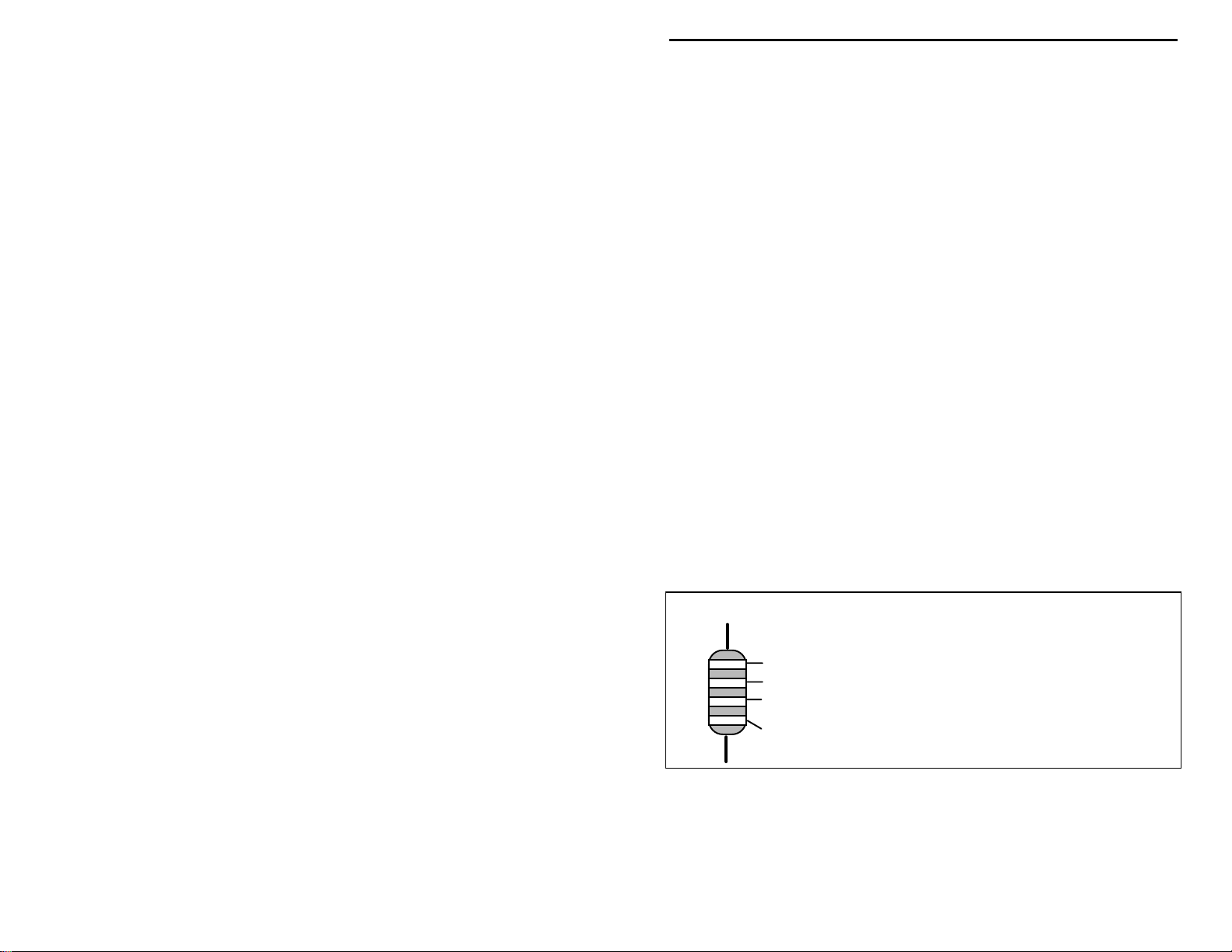
Electrolytic capacitors are always marked in uF. Electrolytics are polarized
devices and must be oriented correctly during installation. If you become
confused by markings on the case, remember the uncut negative lead is slightly
shorter than the positive lead.
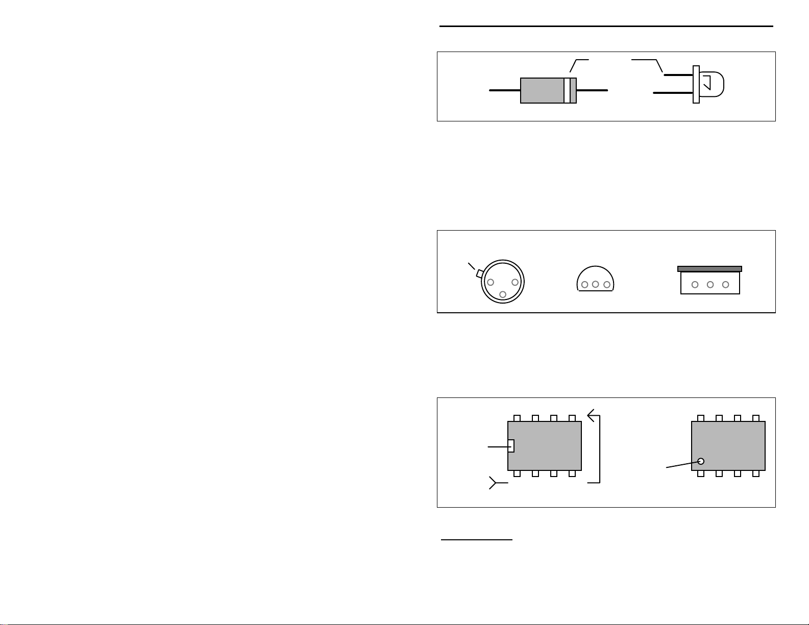
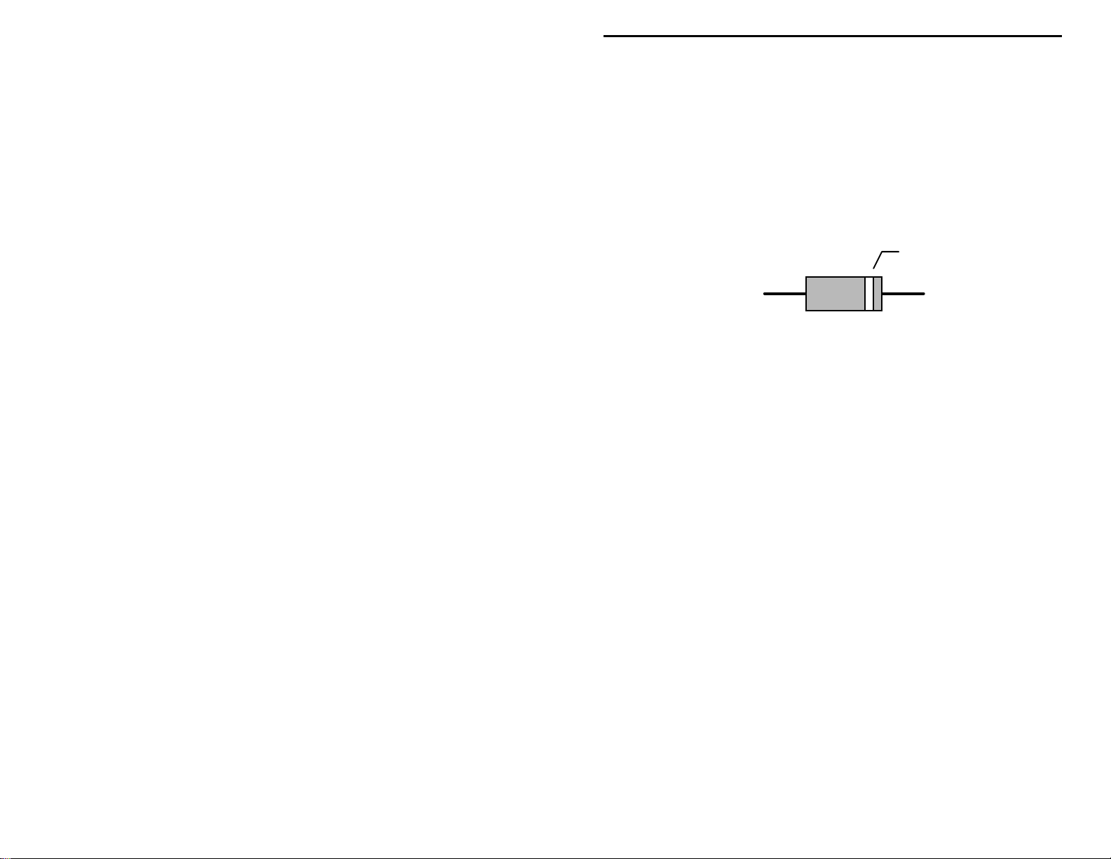
Diodes:
Always look for the banded or cathode end when installing, and follow
instructions carefully.
Diodes are also polarized devices that must be installed correctly.
Unlike resistors, capacitors no longer use a color code for
Electrolytic
1 uF
1uF
|
35V
|
+
-
Multilayer
(270 pF)
271
Ceramic Discs
(.001 uF) (.1 uF)
102
104
4
Page 9
VEC-221K Instruction Manual CW Memory Keyer Kit
Cathode
(shorter Lead)
Diode
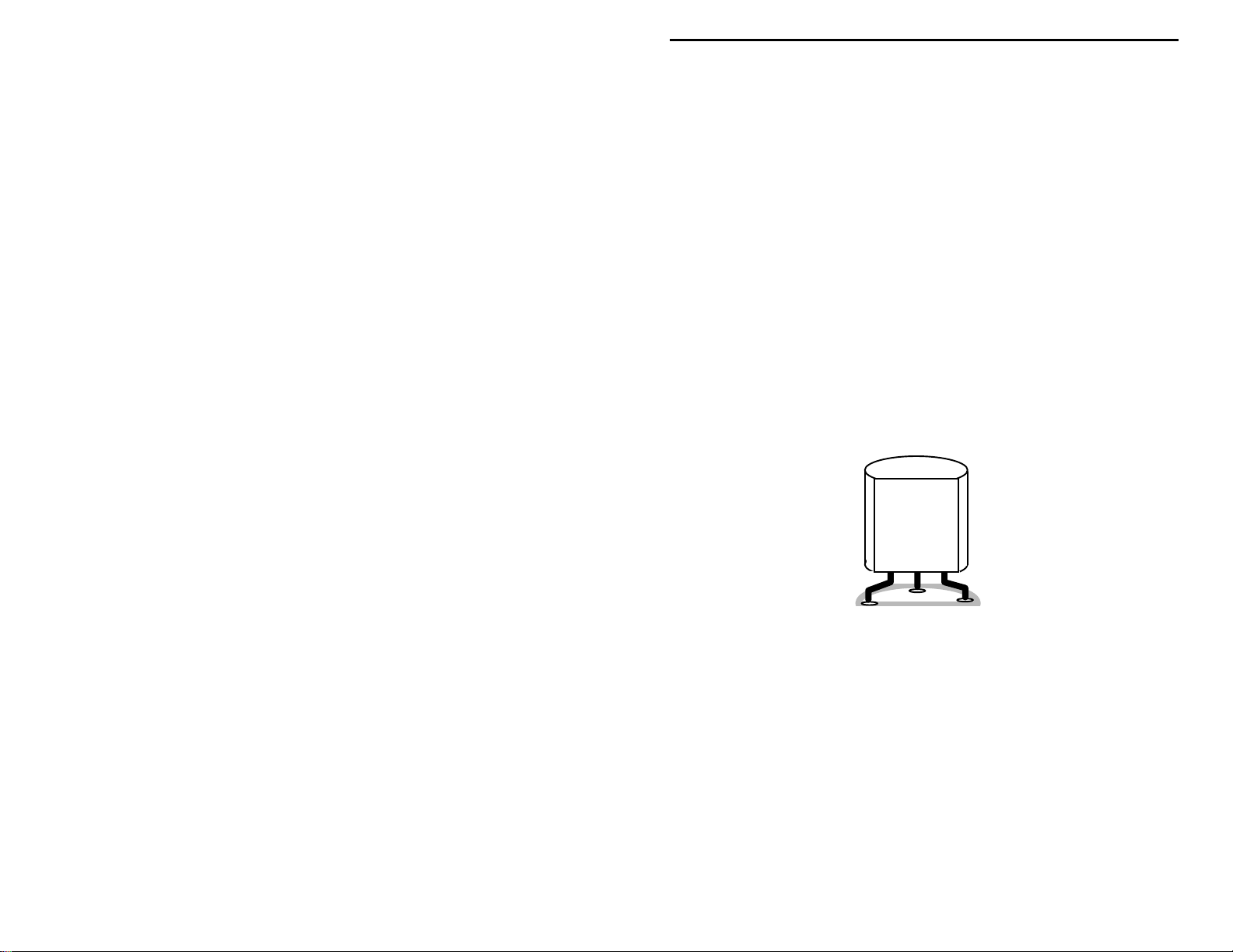
Transistors:
power is applied. Transistors in metal cases have a small tab near the emitter
lead to identify correct positioning. Semiconductors housed in small plastic
cases (TO-92) have an easily-identified flat side to identify mounting orientation.
Many specialized diodes and low-current voltage regulators also use this type
packaging. Larger plastic transistors and voltage regulators use a case backed
with a prominent metal tab to dissipate heat (T-220). Here orientation is
indicated by the positioning of the cooling tab.
If transistors are installed incorrectly, damage may result when
LED
Metal Can Device Plastic Device Tab-cooled Device
Emitter
Flat Side
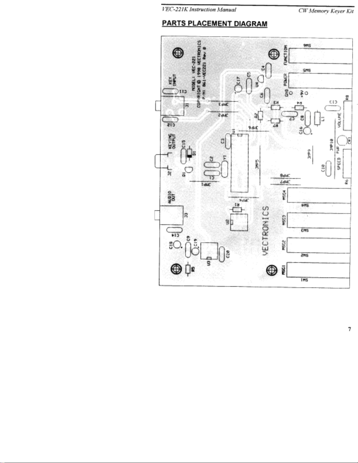
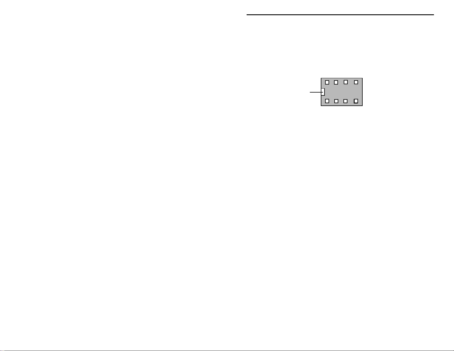
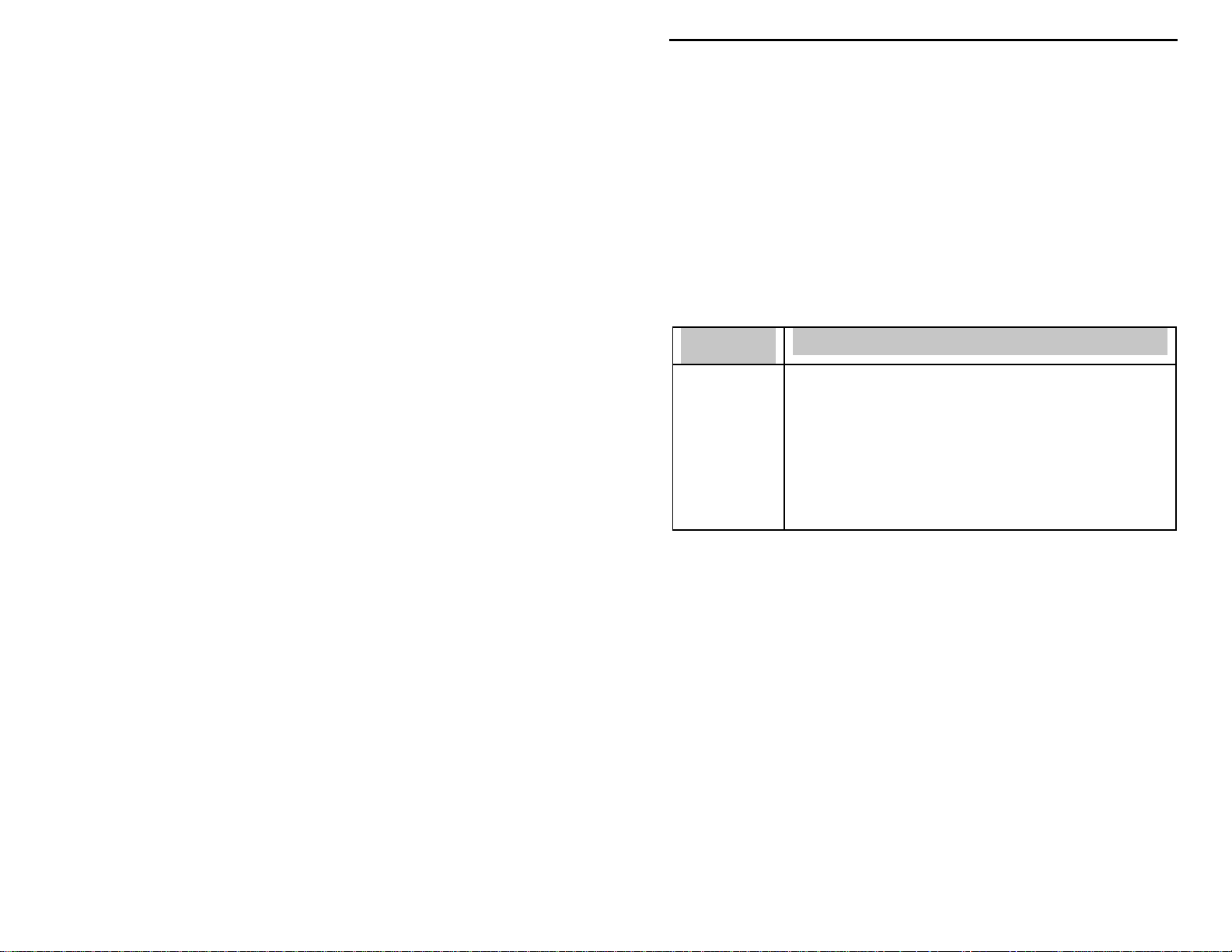
Integrated Circuits:
marking located on one end of the device. A corresponding mark will be silkscreened on the PC board and printed on the kit's parts-placement diagram. To
identify specific IC pin numbers for testing purposes, see the diagram below.
Pin numbers always start at the keyed end of the case and progress counterclockwise around the device, as shown:
Proper IC positioning is indicated by a dot or square
8 7 6 5
Metal Tab
Installation
Key
Installation
Key
1 2 3 4
Pin Numbers
PARTS LIST
Your package kit should c ontain a ll of the p arts li sted be low. Ple ase go through
the parts bag to identify and inventory each item on the checklist before you start
5
Page 10

VEC-221K Instruction Manual CW Memory Keyer Kit
building. If any par ts are missing or damaged, r efer to the warranty section of
this manual for replacement instructions. If you can't positively identify an
unfamiliar item in the bag on the basis of the information given, set it aside until
all other items are checked off. You may then be able to identify it by process of
elimination. Finally, your kit will go together more smoothly if parts are
organized by type and arranged by value ahead of time. Use this inventory as an
opportunity to sort and arrange parts so you can identify and find them quickly.
Qty Part Description Designation
"
!
1 10 ohm (brown-black-black) R5
!
4 1.5K ohm (brown-green-red) R2,R3,R4,R7
!
1 10K ohm (brown-black-orange) R1
!
2 10K ohm potentiometer R6,R8
!
2 22 pF disc ceramic (22 or 220) C1,C2
!
7 0.01 uF disc ceramic (.01 or 103) C10,C11,C12,C13,C14,C15,C20
!
7 0.1 uF disc ceramic (.1 or 104) C3,C4,C5,C6,C7,C8,C9
!
1 0.47 uF electrolytic C16
!
2 10 uF electrolytic C17,C19
!
1 100 uF electrolytic C18
!
1 Red 5 mm round LED CR1
!
1 1N4007 rectifier diode D1
!
1 2N7000 field-effect transistor Q1
!
1 PIC16C72 microcontroller IC U1
!
1 24C04 serial EEPROM IC U2
!
1 LM386 audio amplifier IC U3
!
1 78L05 +5-volt regulator U4
!
1 1000 uH inductor (brown-black-red) L1
!
1 4 MHz crystal Y1
!
2 3.5 mm stereo jack J1,J3
!
1 RCA phono jack J2
!
1 12" length of #22 buss wire For JMP1 - JMP10
!
6 DPDT push-button switch SW1 - SW6
!
2 8-pin IC socket For U2,U3
!
1 28-pin IC socket For U1
!
1 9-volt battery snap clip
!
1 nylon tie wrap
!
1 PC board for VEC-221K
!
1 VEC-221K Owner's Manual
PARTS PLACEMENT DIAGRAM
6
Page 11
Page 12
VEC-221K Instruction Manual CW Memory Keyer Kit
STEP-BY-STEP CONSTRUCTION
Before assembling your kit, please take time to read and understand the VEC kit
warranty printed on the inside cover of this manual. Also, read through the
assembly instructions to make sure the kit does not exceed your skill level. Once
you begin construction, your kit will be non-returnable. Finally, if you haven't
already done so, please verify that all parts listed in the inventory are included.
If anything is missing or broken, refer to the warranty instructions for replacing
missing or damaged parts.
Observe correct polarity when mounting components such as the electrolytic
capacitors, diode, LED, transistor and voltage regulator. If you orient capacitors
so their values face the board edges, you'll be able to read them easily when the
kit is finished. Part designators for components such as R1, C3, etc., appear on
the silk-screened legend on the component-mounting side of the printed circuit
board. These correspond to the drawing shown in the section titled "Parts
Placement Diagram". The parts are inserted on the silk-screen side of the board.
All capacitors should be installed with their bodies as close to the PC board as
possible. This is very important in RF circuits.
If you have la st-minute questions about what you need to build your kit, p lease
refer back to the section titled "Tools and Supplies" . If you're ready to begin
now, let's get started!
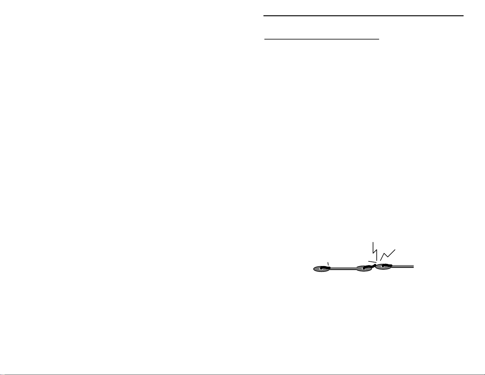
“Install”
identify, and insert the part into its mounting holes on the PC board. This
includes pre-bending or straightening leads as needed so force is not required to
seat the part. Once a component is mounted, bend each lead over to hold it in
place. Make sure trimmed leads don’t touch other pads and tracks, or a short
circuit may result:
“Solder”
leads in place, and to inspect both (or all) solder connections for flaws or solder
bridges. If no soldering problems are noted, nip off the excess protruding leads
with a sharp pair of side cutters.
Notice the directions use two sets of check boxes. Check one when a step is
complete and use the other for double-checking your work before operation.
When you are directed to install a part, this means to locate,
Good
When you are directed to solder, this means to solder the part’s
Not Good
7
Page 13
VEC-221K Instruction Manual CW Memory Keyer Kit
! !
1. Cut the 12 inches wire into ten pieces of appropriate lengths for use as
jumper wires. Use needle-nose pliers to form each one, as shown
below, making sure each rests flat on the PC board when installed:
span
! !
Prepare, install, and solder a jumper wire at JMP1.
! !
Prepare, install, and solder another jumper wire at JMP2.
! !
Prepare, install, and solder another jumper wire at JMP3.
! !
Prepare, install, and solder another jumper wire at JMP4.
! !
Prepare, install, and solder another jumper wire at JMP5.
! !
Prepare, install, and solder another jumper wire at JMP6.
! !
Prepare, install, and solder another jumper wire at JMP7.
! !
Prepare, install, and solder another jumper wire at JMP8.
! !
Prepare, install, and solder another jumper wire at JMP9.
! !
Prepare, install, and solder another jumper wire at JMP10.
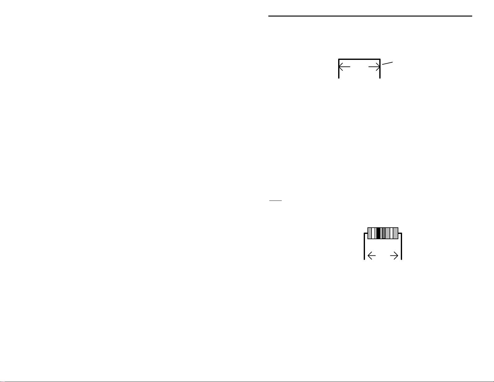
Resistor installation: The resistors packaged in this kit are all 5-percent
Note
:
tolerance ending with a fourth gold color band, only the first three bands
of the color code are needed for the following steps. All resistor leads
should be formed as shown below.
jumper wire
.4"
! !
2. Find the 10 ohm resistor (brown-black-black). Install and solder at
location R5.
! !
3. Find the four 1.5K ohm resistors (brown-green-red). Install and solder
at the following locations:
! !
R2 1.5K ohm resistor (brown-green-red)
! !
R3 1.5K ohm resistor (brown-green-red)
! !
R4 1.5K ohm resistor (brown-green-red)
! !
R7 1.5K ohm resistor (brown-green-red)
8
Page 14
VEC-221K Instruction Manual CW Memory Keyer Kit
! !
4. Find the 10K ohm resistor (brown-black-orange). Install and solder at
location R1.
! !
5. Locate the 1000 uH inductor or choke (brown-black-red). Pre-form
the leads in a similar manner as done for the resistors. Install and
solder at location L1.
! !
6. Locate the 1N4007 rectifier diode. Note that the band indicates the
cathode lead end of the device. Pre-form the leads in a similar manner
as done for the resistors. Install and solder at location D1, be sure to
observe the silk-screened marking for the cathode lead orientation!
Cathode
1N4007
! !
7. Locate the two 22 pF ceramic disc capacitors (marked 22 or 220).
Install and solder at the following locations:
! !
C1 22 pF ceramic disc capacitor (22 or 220)
! !
C2 22 pF ceramic disc capacitor (22 or 220)
! !
8. Locate the seven 0.01 uF ceramic disc capacitors (.01 or 103
marking). Install and solder at the following locations:
! !
C10 0.01 uF ceramic disc capacitor (.01 or 103)
! !
C11 0.01 uF ceramic disc capacitor (.01 or 103)
! !
C12 0.01 uF ceramic disc capacitor (.01 or 103)
! !
C13 0.01 uF ceramic disc capacitor (.01 or 103)
! !
C14 0.01 uF ceramic disc capacitor (.01 or 103)
! !
C15 0.01 uF ceramic disc capacitor (.01 or 103)
! !
C20 0.01 uF ceramic disc capacitor (.01 or 103)
! !
9. Locate the seven 0.1 uF ceramic disc capacitors (.1 or 104 marking).
Install and solder at the following locations:
! !
C3 0.1 uF ceramic disc capacitor (.1 or 104)
! !
C4 0.1 uF ceramic disc capacitor (.1 or 104)
! !
C5 0.1 uF ceramic disc capacitor (.1 or 104)
! !
C6 0.1 uF ceramic disc capacitor (.1 or 104)
9
Page 15
VEC-221K Instruction Manual CW Memory Keyer Kit
! !
C7 0.1 uF ceramic disc capacitor (.1 or 104)
! !
C8 0.1 uF ceramic disc capacitor (.1 or 104)
! !
C9 0.1 uF ceramic disc capacitor (.1 or 104)
! !
10. Locate the 0.47 uF electrolytic capacitor. Install and solder at location
C16 (observe polarity).
! !
11. Locate the two 10 uF electrolytic capacitors. Install and solder at the
following locations (observe polarity):
! !
C17 10 uF (observe polarity)
! !
C19 10 uF (observe polarity)
! !
12. Locate the 100 uF electrolytic capacitor. Install and solder at location
C18 (observe polarity).
! !
13. Locate the 78L05 +5-Vdc voltage regulator IC. Form the leads as
shown below to allow the device to fit at location U4. Make sure the
regulator is properly keyed to the silk-screened outline; if installed
incorrectly, damage to the PIC processor is certain when power is
applied. Install and solder.
78L05
! !
14. Find the 2N7000 field-effect transistor. Position the body outline to
correspond the silk-screened legend at Q1. Install and solder.
! !
15. Find the red LED. Note that the LED has a flat edge corresponding to
the shorter lead. Make sure that the LED is properly keyed to the silkscreened outline at CR1. Install the LED leads until the shouldered
stops on the leads are flush to the PC board Bend the leads so the
LED is flush with the edge of the PC board. Solder.
! !
16. Find the 4 MHz crystal. Install and solder at location Y1.
! !
17. Locate the two 8-pin IC sockets. Note that the socket is “keyed”, and
should be installed with its key aligned to the silk-screened outline on
10
Page 16
VEC-221K Instruction Manual CW Memory Keyer Kit
the PC board. Install and solder the sockets at the following locations.
Make sure key is orientated with board legend.
! !
U2 8-pin IC socket (observe key or i entation)
! !
U3 8-pin IC socket (observe key or i entation)
8 7 6 5
Installation
Key
1 2 3 4
Pin Numbers
! !
18. Install and solder the 28-pin IC socket at location U1. Make sure key
is orientated with board legend.
! !
19. Locate the two 3.5 mm stereo jacks. Install and solder at the following
locations:
! !
J1 3.5 mm stereo jack
! !
J3 3.5 mm stereo jack
! !
20. Find the RCA phono jack. Install and solder at location J2.
! !
21. Locate the six push-button switches. The leads should be fully seated,
and the switch body level to the board. Install and solder at the
following locations:
! !
SW1 push-button switch
! !
SW2 push-button switch
! !
SW3 push-button switch
! !
SW4 push-button switch
Top view of socket
! !
SW5 push-button switch
! !
SW6 push-button switch
! !
22. Switches SW1, SW2, SW3, SW4 and SW6 must be changed from
latching to momentary operation. Follow these directions carefully to
avoid damaging these switches! Set switch so shaft is latched in the
fully extended position. Using a pair of long-nose pliers, carefully lift
the latching clip's end near the switch body (away from the shaft) out
11
Page 17

VEC-221K Instruction Manual CW Memory Keyer Kit
of the switch assembly, and set it to the side of the switch body as
shown below. Be careful not to remove the end under the spring.
! !
23. The front-panel controls are mounted next. Before installing these
parts, inspect the potentiometer supplied with your kit. If the pins are
located on the front side of the pot, use the front set of mounting holes
on the PC board for installation. If the pins are on the rear, use the
rear set of mounting holes (see below). Also, using side cutters,
remove the key tab from the side of each pot prior to installation.
Rear pins use rear holes.
Nip off tab.
! !
24. Install a 10K ohm potentiometer at R6. Insert the potentiometer leads
until the shouldered stops on all three leads are flush to the PC board.
Solder the three leads.
! !
25. Install the other 10K ohm potentiometer at R8, following the
procedures used for R6. Solder.
! !
26. Locate the 9-volt battery clip. Install and solder the free end of the
black lead to the negative (GND) termination point on the PC board.
! !
27. The remaining red battery clip lead should be installed and soldered to
the positive (+9V) termination point on the PC board.
12
Front pins use front holes.
Nip off tab.
Page 18
VEC-221K Instruction Manual CW Memory Keyer Kit
y
! !
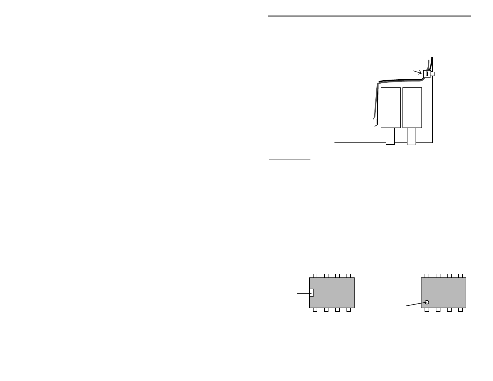
28. The nylon tie wrap should be used to firmly attach the battery clip
wires to the support hole on the PC board. Use the hole located
closest to the e dge of the PC board. Pull the ti e snug and trim excess.
Nylon tie-wrap
SW2
red
black
+
9V
GND
SW1
Important Note:
However, if you are working in a carpeted area, it's always a good idea to touch
a metal ground before handling semiconductors.
! !
29. Locate the PIC16C72. Align its key (see below) with the socket key
U1, U2 and U3 have good immunity to static discharge.
for U1. Be sure that all 28 pins are freely entering the socket holes,
and apply firm pressure to fully seat the IC.
! !
30. Locate the 24C04 EEPROM. Align its key (see below) with the
socket key for U2. Be sure that all 8 pins are freely entering the socket
holes, and apply firm pressure to fully seat the IC.
! !
31. Locate the LM386 audio amplifier. Align its key (see below) with the
socket key for U3. Be sure that all 8 pins are freely entering the socket
holes, and apply firm pressure to fully seat the IC.
8 7 6
Installation
Key
Installation
Ke
1 2 3 4
Pin Numbers
13
Page 19

VEC-221K Instruction Manual CW Memory Keyer Kit
The IC body has a small notch, or key, molded at one end, indicating pin
Note
:
1. A small dimple-like body-molding is often found adjacent to pin 1.
Some IC packages may include both key indicators.
At this point, your kit is finished and it's time to take a well-earned break! When
you come back, be prepared to give your work a close "quality control"
inspection before moving on to the testing and alignment section.
PC Board Inspection:
Before applying power to your kit, give it a thorough QC (quality control)
inspection. This will help you find inadvertent assembly errors that might
prevent the keyer from working or cause damage to sensitive parts. Follow this
procedure:
!
Compare parts locations against the parts-placement diagram. Was each
part installed where it is supposed to be? Was the correct value used? Start
at one side of the board and work your way across in an organized pattern.
!
Inspect the solder side of the board for cold-solder joints and solder bridges
between tracks or pads. Use a magnifying glass to obtain a clear view of the
track area. If you suspect a solder bridge, hold the board in front of a bright
light for a better view. All joints should be smooth and shiny, indicating
good solder wetting and flow. Resolder any beaded or dull-appearing
connections.
Important Note:
two, it will be easier if you have the right tools. One very convenient item for
freeing soldered-in parts is a "solder sucker". This consists of a suction bulb or
a spring loaded vacuum pump that draws molten solder away from the pad and
lead. Alternatively, you may use "solder wick". If you suspect you've damaged a
component during removal, it's better to replace the part than risk reusing it!
If you find a construction error and need to remove a part or
Now that assembly and inspection is completed, you're ready to begin the testing
and alignment phase of construction.
TESTING AND ALIGNMENT
The following items will be needed for testing:
!
9-volt alkaline transistor battery.
!
Keyer paddles (iambic preferred), terminated with 3.5 mm stereo plug.
Wired dot-to-tip and dash-to-ring.
!
4- to 32-ohm headphones or monitor speaker, terminated with 3.5 mm stereo
or mono plug.
14
Page 20

VEC-221K Instruction Manual CW Memory Keyer Kit
Actuate push-button switches SW1 to SW6 a few times and note the latching
action. The switches will toggle from off to on; the on condition exists when the
shaft remains partially recessed; off when the shaft is fully extended.
!
Set Power switch SW5 to off.
!
Attach the paddle plug to jack J1 (Key Input) on the PC board.
!
Attach a monitor speaker or headphones to jack J3 (Audio Out.)
!
Connect a fresh 9-volt battery to the battery clip.
!
Perform the self-test described below.
Self Test
A self-test routine is used to check the functions of the unit. This routine checks
the paddles, the push-button switches, the knob, the non-volatile memory and the
audio circuitry. During the self-test, you may stop the test by turning off the
unit; however, this should NOT be done during the memory test or the memory
could be corrupted. This self-test can be completed in approximately one
minute.
Performing the self-test will reset the unit to its factory default settings.
Note
:
Here is the self-test procedure:
1. Turn off the unit.
2. Turn the Speed control R6 to full clockwise position.
3. Set the Volume control R8 to a comfortable listening level (midrange).
4. Squeeze the paddle while turning the power on by pressing the Power switch
SW5. The test begins by sending a copyright message
VECTRONICS VX.XX"
. This is the test of the audio circuitry. Release the
"(c) 199X
paddles before this message completes.
5. The LED should be off after the copyright message is finished. For the
entire test, the LED should blink once after each operation. If the LED
blinks continuously, the unit fails the test and a Morse code message is sent
to indicate the nature of the failure.
6. Press and release the dot level (connected to the tip of the plug).
7. Press and release the dash level (connected to the ring of the plug).
8. Press and release the Message 1 switch SW1.
9. Press and release the Message 2 switch SW2.
10. Press and release the Message 3 switch SW3.
15
Page 21
VEC-221K Instruction Manual CW Memory Keyer Kit
11. Press and release the Message 4 switch SW4.
12. Press and release the Function switch SW6.
13. Turn the Speed control R6 to full counter-clockwise position.
14. Turn the Speed control R6 to full clockwise position.
15. The unit then tests its non-volatile memory. This step will reset the unit to
its factory default values.
16. If the unit is okay,
"PASS"
is repetitively sent to the speaker. If there is a
problem, a failure message is sent, indicating that you did not follow the
correct order or the unit failed the test. These messages are shown below.
17. Once you have confirmed that the audio is okay, turn the unit off.
Failure
Message
DH FAIL
DT FAIL
EE FAIL
FN FAIL
M1 FAIL
M2 FAIL
M3 FAIL
M4 FAIL
SP FAIL
Dash level is shorted or improperly connected.
Dot level is shorted or improperly connected.
Non-volatile memory circuitry is improperly connected.
Function switch is shorted or improperly connected.
Message 1 switch is shorted or improperly connected.
Message 2 switch is shorted or improperly connected.
Message 3 switch is shorted or improperly connected.
Message 4 switch is shorted or improperly connected.
Speed control is faulty.
Meanings
Now that the self-test is completed, you're ready to continue the testing and
alignment phase of construction.
!
Preset Volume control R8 to midrange.
!
Preset Speed control R6 about 30% clockwise from the full counter-
clockwise stop.
!
Turn the keyer on using Power switch SW5.
!
Press and hold the dot paddle—you should hear a stream of “dits” from the
monitor speaker.
!
Press and hold the dash paddle—you should hear a stream of “dahs” from
the monitor speaker.
!
While generating a continuous stream of “dits” or “dahs”, verify that
adjusting Volume control R8 varies the monitor sidetone level.
!
While generating a continuous stream of “dits” or “dahs”, verify that
adjusting Speed control R6 va ries the sending rate.
16
Page 22

VEC-221K Instruction Manual CW Memory Keyer Kit
!
If your paddle is iambic, squeeze both paddles—this should produce a
continuous strea m of a l ternating “dits” and “dahs”.
!
Activate Function switch SW6. The keyer should verify that the function
mode has been entered by sending a Morse character “F” (di-di-dah-dit).
!
Enter the Morse character for the letter “S” (di-di-dit) via the paddles. The
keyer should respond with two beeps, indicating an invalid command.
!
Activate Function switch SW6. The keyer should verify that the function
mode has been entered by sending a Morse character “F” (di-di-dah-dit).
!
Enter the Morse character for the letter “R” (di-dah-dit) via the paddles. The
keyer will respond with a single beep indicating a valid command entry.
(This command reverses the action of the dot and dash paddles.)
!
Try your dot and dash paddles—the paddle action should be reversed.
!
Turn the unit off. Note that the reversed paddle orientation will resume
when power is reapplied. This indicates the function command is saved into
the non-volatile memory and ready to be used the next time without having
to set it again.
This completes the testing phase of the VEC-221K keyer. No alignment is
needed.
OPERATING INSTRUCTIONS
Dits, dahs, dots and dashes?
composed of strings of dots and dashes, the visual image conveyed when
viewing Morse CW characters on the printed page. Experienced CW operators
tend to think of CW characters as a sound, and hear dahs instead of dashes, and
dits instead of dots when listening to CW characters. Both terms will be used
interchangeably in the following text.
Determining keyer speed:
generated in a five-second p eriod. The number o f dashes roughly equals your
CW sending speed .
Enclosure:
to provide your own enclosure, allow room for the battery, and perhaps the
sidetone monitor speaker. The optional Vectronics VEC-221KC enclosure is
custom made for the VEC-221K keyer, and includes knobs, push-buttons, feet
and decals.
Power requireme nts:
source. An alkaline battery will give long service, but always remember to turn
the keyer power switch off when the keyer is not being used.
An enclosure will protect the keyer from damage. If you are going
Beginners often t hink of CW character s as being
Hold the dash lever and count the number of dashes
The keyer is designed to operate from a 9-volt DC battery
17
Page 23

VEC-221K Instruction Manual CW Memory Keyer Kit
Experienced builders may opt to power the VEC-221K from an external power
source. The absolute maximum DC supply voltage is limited to 12 Vdc by the
LM386 specifications. Keyers damaged by over-voltage conditions will not be
honored under the terms of the
Warranty
.
Keyer paddles:
Most popular paddles will work well with the VEC-221K. Full
enjoyment of the VEC-221K’s features requires paddles that are capable of
iambic operation. We recommend the Vectronics iambic paddles as being a
good value. Iambic paddles can be recognized by the totally independent
operation of the Dit (or “Dot”) and Dah (or “Dash”) paddles. Some CW
operators refer to iambic paddles as “squeeze paddles”.
The paddles should be equipped with a three-wire interconnecting cable
terminated in a 3.5 mm stereo jack. Miniature shielded and balanced
microphone cable is ideal for this. The common return is connected to the
longest “ring” (shaft) of the stereo jack. The Dah paddle connection is made to
the jack terminal for the smaller insulated ring. The Dit paddle is connected to
the jack tip connection. If your paddles are equipped with a ¼” stereo jack, a
suitable stereo adapter is available at most electronic or hi-fi shops. Reversed
paddle wiring can be corrected by a function entry, more on this later. The
paddles are connected to J1 on the VEC-221K.
Tip (dit)
Common
Ring (dah)
3.5mm stereo jack. Refer to the connector
packaging for wiring terminal details.
Linear controls:
There are two linear controls. Potentiometer R8 sets the
sidetone monitoring level. The second control, potentiometer R6, sets the CW
speed over a range of 3 wpm (words-per-minute) to 65 wpm. This is for good
reason, these are the controls that are most frequently adjusted.
Sidetone operation:
The sidetone is tone keyed by the CW keyer. This permits
you to monitor your keying and provides the aural “feedback” to assist in
sending good CW. Many transceivers already provide for internal CW sidetone
monitoring. If your transmitter does not have built-in sidetone monitoring
provisions, the VEC-221K will generate a sidetone for you. Either a monitor
speaker (4 to 32 ohms) or headphones equipped with a 3.5 mm stereo or mono
18
Page 24

VEC-221K Instruction Manual CW Memory Keyer Kit
jack should be attached to J3 to monitor the CW sidetone. Adjust potentiometer
R8 (sidetone level) to a comfortable listening level.
Factory defaults status:
turned on by depressing Power switch SW5, the unit is ready for operation. A
microprocessor program “subroutine” loads several operating parameters into
the keyer at power up. These parameters are the same as the last time you turn
the unit off, many of them may be changed to suit your preferences—more on
this later. Commands entered via the Function switch are stored in non-volatile
memory.
At factory default settings, the keyer assumes standard paddle wiring, that is dit
key to tip and dah key to the ring of the 3.5 mm jack. Iambic operation is set to
mode “A”. The sidetone frequency is set to 701 Hz. The CW weight is set to
50%, the standard 1:3 dit to dah ratio. The keyer is in the automatic mode.
If CW opera tion is a new experience fo r you, consider runni ng the keyer in its
basic default configuration until you become comfortable with its feel and
operation. Feel free to learn the more advanced features at your own pace.
Factory default settings after the self-test:
1. 701 Hz sidetone
2. Standard weight (50%, dot-dash-space ratio of 1:3:1)
3. Iambic A
4. Automatic
5. Standard paddle wiring (dot = tip, dash = ring)
6. Serial number = 0001
7. Leading zeros sent as "O" (dah-dah-dah)
8. Other zeros sent as "0" (dah-dah-dah-dah-dah)
9. Nines sent as "9" (dah-dah-dah-dah-dit)
As soon as power is supplied and the VEC-221K
Transmitter keying:
need a cable to connect between the keyer and the CW keying jack of your radio.
The operation instructions for your set should show what sort of connector is
needed and its location on your radio. Many modern transceivers use RCA
phono jacks for connecting accessories, in those cases ready-made cables for
home entertainment devices may be used between the VEC-221K and radio.
Keyer output specs:
modern solid-state transceivers and QRP transmitters meet this requirement.
Always check the owner’s manual before attaching the keyer to a radio. The
VEC-221K will key positive voltages to 50 Vdc maximum. Keying current is
limited to 100 mA maximum. Exceeding these limits may damage keying
transistor Q1.
The keyer output is through RCA phono jac k J2. You will
The keyer is de signed for
positive keying output
. Most
19
Page 25

VEC-221K Instruction Manual CW Memory Keyer Kit
Use with vintage sets:
be compatible with the VEC-221K. If the transmitter uses grid-block keying (a
negative key voltage), it can not be used with the VEC-221K. An example of a
grid-block keyed transmitter is the Heathkit DX60. Check the ARRL handbooks
for circuit s for adapti ng keyers to grid-b lock keying.
Vintage novice transmitters commonly used cathode keying, a combination of
high current and high voltage. The Heathkit DX40 used cathode keying, for
example. In general, most cathode-keyed transmitters should be compatible with
the VEC-221K keying circuit, so long as the 50 Vdc and 100 mA limits are not
exceeded.
Dot-and-dash memories and iambic keying:
making sending CW easi er. T he memor y allows the user to ke y a dot b efo re the
completion of a dash, and vice-versa. This feature maybe checked by setting the
keyer to the lowest speed and tapping first the dash lever and then the dot lever
before the completion of the dash. The keyer will generate both the dash and the
dot with perfect spacing. Test the dash memory in a similar manner. First tap
the dot lever and quickly tap the dash lever. The keyer will send the dot
followed by the dash, again with perfect character spacing.
Iambic paddles allow both paddles (or levers) to be depressed at the same.
Pressing (squeezing) both paddles simultaneously will generate a continuous
stream of alternating dots and dashes. The first paddle contacted determines
whether a dot or dash occurs first. CW characters such as "C", "K", "Q" and
"R" are very easily generated with iambic paddles.
Early tube transmitters and hybrid transceivers may not
The dot and dash memories
Non-volatile memory:
number, the keyer settings, and the four message memories. Because it is nonvolatile, it does not require battery backup to preserve the memory.
Special Functions
All programmable special functions are saved in non-volatile memory.
Note
:
These settings are restored at power on.
Automatic mode :
send high-speed code. T he bug would automatic ally send a string of dits when
the dot paddle was depressed and held. Bugs did not generate strings of dashes,
the dash had to be depressed once to generate each individual “dah”. The VEC221K normally operates in the fully automatic mode. However, it may be set for
“semi-automatic” operation, to emulate the sound and feel of a mechanical bug.
Weight:
operators prefer slightly different ratios; and the VEC-221K weight is adjustable
from 25 to 75% of a dot to suit those preferences. The factory default is 50%, or
3:1 dash-to-dot ratio.
20
A 3:1 ratio between dit’s and dah’s is considered to be optimum. Some
The non-volatile memory is used to store the serial
Early telegraphers used a mechanical device called a bug to
Page 26
VEC-221K Instruction Manual CW Memory Keyer Kit
Sidetone frequency:
sidetone may be programmed from approximately 300 to 1000 Hz to suit
individual tastes. There are two ways of setting the sidetone frequency.
Reverse:
paddle is shared by both left and right handed operators.
Iambic modes A and B:
iambic "A" mode.
Serial number:
Only three digits are sent for numbers less than 1000--use leading zeros when
appropriate. The serial number is automatically post-incremented each time it is
sent (9999 will increment to 0001, skipping 0000 since it is not used) and is
updated in the non-volatile memory when the message is finished. The factory
default is 0001.
Zeros and nines:
ways. The factory defaults are leading zeros as "O" (dah-dah-dah), other zeros
as "0" (dah-dah-dah-dah-dah), and nines as "9" (dah-dah-dah-dah-dit).
Using the Function switch:
preferences. To set or change a setting, depress the Function switch. The keyer
acknowledges by sending the Morse character for the letter "F" (di-di-dah-dit).
Keyer functions are entered via the keyer paddles. If an invalid character is
entered, the keyer responds with two beeps. Multiple functions may not be
entered at one time. That is, each function must be individually entered and
preceded by pressing the Function switch. A valid entry is acknowledged by a
single beep. The transmitter key line is disabled during programming. The
function mode maybe exited at any time by pressing the Function switch. The
keyer confirms the exit with two beeps.
Reverses the sense of the left and right paddles. Useful when the
The factory default sidetone is about 701 Hz. The
Either mode may be selected. Factory default is
A four digits serial number can be embedded within a message.
Zeros and nines in t he serial number can b e sent in differe nt
The Function switch customizes the keyer to your
Command
Character
A
I#
Function
utomatic−toggles between automatic and semi-automatic (bug)
A
mode.
ambic−sets iambic mode A or B, where # represents A or B.
I
21
Page 27

VEC-221K Instruction Manual CW Memory Keyer Kit
####
N
umber−sets the seri al number. You must enter four numbe rs,
N
most significant digit first. All numbers must be in the proper
Morse code format. For example, the number "1" must be "didah-dah-dah-dah" and the number "0" must be "dah-dah-dahdah-dah". The serial number can be set from 0000 to 9999
(0000 will be converted to 0001).
P##
R
T
W##
X
###
Z
itch−sets the sidetone frequency to approximately ##0 Hz,
P
where ## represents two digits in the range of 30 to 99.
everse−reverses the sense of the dot and dash paddles.
R
one−sets the sidetone frequency in the range of approximately
T
300 to 1000 Hz. Press the dash paddle to raise the sidetone
frequency; press the dot paddle lowers. Squeeze both paddles
exits. Notice an alternating series of dots and dashes are sent to
the sidetone monitor to assist in the setting of the desired
sidetone fre quency.
eight−sets the code weighting to ## percent, where ##
W
represents two digits in the range of 25 to 75. Weighting is
independent of the speed.
mit (tune)−gives continuous key-down for adjusting transmitter
X
or antenna tuner. Tapping either paddle exits tune mode and
releases the key line.
eros and nines−sets the way zeros and nines in the serial
Z
number are sent. The first # sets whether to send the leading
zeros as "0", "O", "T" or not at all by setting # to the double
dash character "=" (dah-di-di-di-dah). The second # sets
whether the other zeros are sent as "0", "O" or "T". The last #
sets whether the nines are sent as "9" or "N". For example,
"ZO09" will send the leading zeros as "O" (dah-dah-dah), the
other zeros as "0" (dah-dah-dah-dah-dah), and the nines as "9"
(dah-dah-dah-dah-dit).
Message Memory
The Message buttons are used to record and play your message. To record a
message, press and hold the corresponding Message button until the keyer plays
"GO" (dah-dah-dit dah-dah-dah) in Morse code and the LED flashes. You may
now key in the message of your choice. As you pause after every word, the
keyer will play a "W" (di-dah-dah) over the sidetone speaker to show that it is
22
Page 28
VEC-221K Instruction Manual CW Memory Keyer Kit
inserting a word break (uses one unit of memory). If you make a mistake
entering a word, you can back up over it by briefly pressing and releasing the
same Message button. The keyer will erase the last word, then play the word
before it (if any) to let you know where you stopped. If deleting the first word of
the message, the keyer will play "GO" instead. At the end of your message,
press and hold the same Message button until the keyer sends an end of message
character "+" (di-dah-di-dah-dit) and the LED stops flashing. If you try to save
more characters than you have memory, the keyer will automatically end your
message and send you an end of message character. To play a message,
momentarily press the cor r esp ond ing M essa ge b utt on. On-go ing message ca n be
stopped by tapping either paddle or pressing a Message button to send another
message. The speed cannot be changed during message sending and message
recording. Also, the output keying circuit is disabl ed during recording.
The messages are stored in non-volatile memory: message 1 has 120 units of
memory and the other three messages have 128 units of memory each. Each
normal character uses one unit of memory; only the rarely used 7-, 8- and 9element (dots and dashes) characters require two units of memory. Characters
with more than nine elements are ignored. When there are ten or less units of
memory in the message remaining, the LED will flash faster to let you know the
memory is running low.
Note
A straight key cannot be used to record the message.
:
Embedded Commands:
While in the message recording mode you may use embedded commands for
special features. To use an embedded command simply store the multi-character
embedded command code within your message.
Embedded
Command
/D
ecrement−decrements the serial number. Serial number 0001
D
Represents
will decrement to 9999, skipping 0000 since it is not used. This
feature allows a serial number to be sent twice in a message.
Example:
UR RST 559 559 SN /N /D SN /N
23
Page 29

VEC-221K Instruction Manual CW Memory Keyer Kit
/G#
/L
/N
mmss
/P
ap−inserts a gap of # standard intra-character spaces into the
G
message, where # is a digit in the range of 1 to 9 (0 can be used
but not practical). Invalid numeral code will automatically
default to zero. This command is used to exaggerate intercharacter and word spacing.
oop−creates a message loop (message repeat). Note that any
L
character recorded after
Example:
umber−inserts a contest serial number, in the range of 001 to
N
BEACON AA5CS 5 W /L
"/L"
will not be sent.
9999, into the message. Only three digits are sent for numbers
less than 1000--use leading zeros when appropriate. The serial
number is automatically post-incremented each time it is sent
(9999 will increment to 0001, skipping 0000 since it is not used)
and is updated in the non-volatile memory when the message is
finished. The serial number is set to the same one as before
when power on. If a different serial number is desired, it must
be set using the paddle-entered Number function.
Example:
ause−inserts a timed pause of mm minutes and ss seconds into
P
YOU ARE CONTACT NR /N
the message. Four numbers must fol low "/P". Invalid numeral
code will automatically default to zero.
Example:
TIMEOUT 1 HR 40 MIN 39 SEC /P9999
TIMEOUT 1 HOUR /P6000 TIMEOUT 1.5 MIN /P0090
/S
pace−inserts an extra standard word space into the message.
S
This command yields the same result as "/G7" but uses one less
unit of memo ry.
//
/#
Slash character−stores the slash character "/" into the message.
Message call−inserts message number # into the current
message, where # is a digit from 1 to 4.
Morse Code Character Set 1
A di-dah
B dah-di-di-dit
C dah-di-dah-dit
D dah-di-dit
E dit
F di-di-dah-dit
G dah-dah-dit
−
N dah-dit
•
−
•••
−•−
•
−
Q dah-dah-di-dah
••
R di-dah-dit
•
••−•
−−
T dah
•
24
−
O dah-dah-dah
P di-dah-dah-dit
S di-di-dit
−−−
•−−•
−−•−
•−•
•••
−
•
Page 30

VEC-221K Instruction Manual CW Memory Keyer Kit
H di-di-di-dit
I di-dit
J di-dah-dah-dah
K dah-di-dah
L di-dah-di-dit
M dah-dah
1 di-dah-dah-dah-dah
2 di-di-dah-dah-dah
3 di-di-di-dah-dah
4 di-di-di-di-dah
5 di-di-di-di-dit
Period [.] di-dah-di-dah-di-dah
Comma [,] dah-dah-di-di-dah-dah
Question Ma rk or
Request for Repetition [?] di-di-dah-dah-di-dit
Fraction Bar [/] dah-di-di-dah-dit
End of Message or Cross [+] di-dah-di-dah-dit
End of Work di-di-di-dah-di-dah
Double Dash, Pause or Break [=] dah-di-di-di-dah
Semicolon [;] dah-di-dah-di-dah-dit
Colon [:] dah-dah-dah-di-di-dit
Apostrophe ['] di-dah-dah-dah-dah-dit
Quotation Ma rk ["] di-dah-di-di-dah-dit
Hyphen or Dash [-] dah-di-di-di-di-dah
Underline [_] di-di-dah-dah-di-dah
Dollar Sign [$] di-di-di-dah-di-di-dah
Left Parenthesis [(] dah-di-dah-dah-dit
Right Parenthesis [)] dah-di-dah-dah-di-dah
Wait di-dah-di-di-dit
Understood di-di-di-dah-dit
Starting Signal dah-di-dah-di-dah
Error di-di-di-di-di-di-di-dit
Paragraph [¶] di-dah-di-dah-di-dit
Invitation to Transmit dah-di-dah
1.
FCC test requirement consists the 26 letters, the 10 numerals, the period, the comma, the question mark, AR, SK, BT and DN.
U di-di-dah
••••
V di-di-di-dah
••
−−−
W di-dah-dah
•
−•−
X dah-di-di-dah
Y dah-di-dah-dah
•−••
−−
Z dah-dah-di-dit
−−−−
6 dah-di-di-di-dit
•
−−−
7 dah-dah-di-di-dit
••
−−
8 dah-dah-dah-di-dit
•••
−
9 dah-dah-dah-dah-dit
••••
0 dah-dah-dah-dah-dah
•••••
−
••
−
•••
−−
•
−••−
−•−−
−−
••
−
••••
−−
•••
−−−
••
−−−−
•
−−−−−
−
•−•−•
−−••−−
••−−••
−••−
•
•−•−•
−
•••−•
−
−
•••
−•−•−
•
−−−
•••
−−−−
•
•
•−••−•
−
−
••••
−
••−−•
−
•••−••
−•−−
•
−•−−•−
•−•••
•••−•
−•−•−
••••••••
•−•−••
−•−
K
AAA
MIM
IMI
DN
AR
SK
BT
KR
OS
WG
AF
DU
IQ
SX
KN
KK
AS
SN
KA
HH
AL
IN CASE OF DIFFICULTY
Only high-quality components and proven circuit designs are used in Vectronics
kits. In very rare instances is a defective component the source of a problem.
Replacement of defective parts is covered in the
Warranty
section. Nine ty-five
percent of the kits returned for factory repair are due to soldering problems or
parts in the wrong locations. We advise repeating the assembly instructions
step-by-step, looking for mistakes or soldering problems. Be especially wary of
electrolytic capacitors and semiconductors. Kit builders often miss obvious
25
Page 31

VEC-221K Instruction Manual CW Memory Keyer Kit
mistakes. What is needed is a “fresh” set of eyes. Enlist a friend to go over your
work.
Always check the obvious! Is the battery dead or weak? Is the power switch on?
Check the keying cable and paddle cable for intermittent or broken wires. Note
that the solder connections for the various jacks may fail due to stress from
frequent insert ion and removal o f plugs.
Trouble shooting guide:
Performing the self-test will isolate the problems in most cases.
No sidetone, but keying line actuates:
from pin 13 of U1. Look for the sidetone signal at R2, R3, R4, C13, pin 3 of
U3, pin 5 of U3, and both sides of C18 to isolate problem stage. Set scope for
AC coupling, 100 mV (or higher, as needed) per-division. Pin 6 of U3 should
show 9 Vdc. Pin 5 of U3 should measure about 4.5 Vdc with no tone (use scope
or VOM).
Dot or Dash characters not being generated:
going logic leve l at pin 28 of U1. Dash l evel should produce low-going logic
level at pin 2 7 of U 1. Che ck pi n 12 o f U1 for high-going CW signal . Check for
5 Vdc on pins 1 and 20 of U1. Set scope for DC coupling, 1 volt-per-division.
Sidetone okay, but keyline remains low:
from pin 12 of U1 when paddles are actuated. Set scope for DC coupling, 1
volt-per-division. Presence of signal indicates possible failure of Q1 or D1.
Keyer dead:
U1. Loss of 5 volts may indicate failure of U4 voltage regulator.
Sidetone distorted, erratic operation:
keyer; use an enclosure and shielded leads.
Can’t enter function mode:
U1.
Can’t enter message mode:
logic low on pins 21, 22, 23 and 24 of U1, respectively.
LED not lit:
screened outline. Check for 5 volts at R7 and a logic low on pin 18 of U1.
Check for 9 volts at pin 6 of U3. Check for 5 volts at pin 20 of
Pressing SW6 should put a logic low on pin 25 of
Pressing SW1, SW2, SW3 and SW4 should put a
Check the LED to make sure it is properly keyed to the silk-
Use a scope to view the sidetone signal
Dot lever should produce low-
Check for high-goi ng logic signal
Weak battery. There is RF getting into
Keyer gives error beeps on function entry:
formed, with proper timing. Invalid command prefix or suffix.
Code characters must be perfectly
THEORY OF OPERATION AND SPECIFICATIONS
26
Page 32

VEC-221K Instruction Manual CW Memory Keyer Kit
Circuit Description:
The VEC-221K features the powerful PIC16C72 microcontroller. This
integrated circuit contains the programming and basic power of a microprocessor
chip. CW speed is set via R6, a 10K-ohm potentiometer, that controls the
voltage input to pin 2 of U1 (PIC chip). Pin 2 is an analog-to-digital input for
the PIC processor. Programming subroutines scan the digitized setting of R6,
and adjust the speed accordingly.
Keyer paddle activation is also sensed by the PIC chip. All dot-and-dash
memories, iambic operations, and sidetone generation and sidetone frequency
are under the control of the PIC16C72 device.
The message memories and parameter settings are stored in the 24C04
EEPROM, a non-volatile memory IC that does not require battery backup to
preserve the recorded messages and settings.
Power to the PIC controller is regulated at 5 volts by 78L05 (U4), a low-power
5-Vdc regulator IC. The sidetone signal from the processor is filtered by R2-C6,
R3-C7, R4-C8 and L1-C16 to form a sinewave signal, which is amplified by U3,
a linear audio amplifier IC. U3 is powered directly from the 9-volt battery.
Transistor Q1 is a silicon-gate TMOS switching FET, and is used to key the
transmitter. The maximum FET ratings are 50 Vdc at 100 mA.
Specifications:
Voltage requirement........................Internal 9-volt transistor battery
Keyer speed.....................................Typically 3 to 65 WPM
Sidetone level..................................50 mW max., adjustable
Sidetone frequency..........................701 Hz default, adjustable 300 to 1000 Hz.
Keying limit.....................................Positive keying. 50 volts at 100 mA max.
CW generation.................................Iambic A or B, Automatic or Semi-auto
Memory...........................................Dot-Dash memory
Weight.............................................50% default, adjustable 25 to 75 percent
Message memories ..........................4 messages, about 120 characters each
SCHEMATIC
27
Page 33

Page 34

VEC-221K Instruction Manual CW Memory Keyer Kit
ENCLOSURE
Vectronics has designed a matching enclosure just for your VEC-221K CW
Memory Keyer Kit. The matching enclosure is an all metal box which includes
knobs, hardware, decals, and rubber feet.
Enclosure Model: VEC-221KC.
To install your receiver in the VEC-221KC matching enclosure follow these
instructions (read
Find the front and rear panel decal; separate using scissors. Put the rear
1.
panel decal on first. This is done by:
chassis.
decal on the rear panel without securing it completely.
all
instructions before beginning ... take your time):
Remove all debris and oil from the
a.)
Remove the crack and peel to expose the adhesive.
b.)
c.)
Gently rub the
d.)
alignment circles with your finger--if the circles are centered in the enclosure
holes (also check the corner alignment marks) secure the decal by rubbing
and removing all air bubbles.
adjust the decal accordingly, then secure.
TM
Exacto
holes.
Next, install the two L-brackets on the chassis using two of the 3/16" screws.
2.
knife, to cut away the unused edges and cut out the component
Repeat procedure for the front panel.
g.)
If the alignment circles are not centered,
e.)
Use a penknife, or small
f.)
The longer side of the L-bracket must be connected to the chassis using the
two holes centered on each edge of the enclosure. Refer to the diagram on
the next page for location and orientation.
Install the four 1/2" mounting screws next. Insert the screws, from the
3.
bottom, through the two holes close to each rear corner of the chassis.
Place the four 3/16" round spacers on the mounting screws.
4.
Now insert the PC board. This must be done by:
5.
washers from R6 and R8.
Insert the front of the PC board at an angle,
b.)
Remove the nuts and
a.)
then push down on the rear of the board. Make sure the mounting screws
align with the mounting holes in the PC board before pushing.
Use the four hex nuts to secure the PC board. Be certain all appropriate
6.
components are centered with the enclosure holes before tightening. Put the
washers and nuts--removed from R6 and R8--back on and tighten.
Find the knobs and switch caps. Align the switch cap with SW1 and push it
7.
on. If it is difficult to push on, then rotate it 90° and try again. Repeat for
SW2 through SW6. Now put the kno bs on R6 and R8. You may need to
loosen the set screw. Align appropriately then tighten the set screw.
The top should now be installed. Use the two remaining 3/16" screws for
8.
securing the top to the L-brackets.
Place the four rubber feet on the bottom of the enclosure at the corners.
9.
Place the
c.)
28
Page 35

 Loading...