

Page 1

VEC-201K Owner's Manual CW Keyer Kit
CW - Keyer
VEC-201
Page 2

VEC-201K Owner's Manual CW Keyer Kit
IMPORTANT WARRANTY INFORMATION! PLEASE READ
Return Policy on Kits When Not Purchased Directly From Vectronics: Before continuing any
further with your VEC kit check with your Dealer about their return policy. If your Dealer allows
returns, your kit must be returned before you begin construction.
Return Policy on Kits When Purchased Directly From Vectronics: Your VEC kit may be re-
turned to the factory in its pre-assembled condition only. The reason for this stipulation is, once
you begin installing and soldering parts, you essentially take over the role of the device's manufac-
turer. From this point on, neither Vectronics nor its dealers can reasonably be held accountable
for the quality or the outcome of your work. Because of this, Vectronics can not accept return of
any kit-in-progress or completed work as a warranty item for any reason whatsoever. If you are a
new or inexperienced kit builder, we urge you to read the manual carefully and determine
whether or not you're ready to take on the job. If you wish to change your mind and return your
kit, you may – but you must do it before you begin construction, and within ten (10) working
days of the time it arrives.
Vectronics Warrants: Your kit contains each item specified in the parts list.
Missing Parts: If you determine, during your pre-construction inventory, that any part is missing,
please contact Vectronics and we'll send the missing item to you free of charge. However, before
you contact Vectronics, please look carefully to confirm you haven't misread the marking on one
of the other items provided with the kit. Also, make certain an alternative part hasn't been substi-
tuted for the item you're missing. If a specific part is no longer available, or if Engineering has de-
termined that an alternative component is more suitable, Vectronics reserves the right to make
substitutions at any time. In most cases, these changes will be clearly noted in an addendum to
the manual.
Defective Parts: Today's electronic parts are physically and electrically resilient, and defective
components are rare. However, if you discover an item during your pre-construction inventory
that's obviously broken or unserviceable, we'll replace it. Just return the part to Vectronics at the
address below accompanied with an explanation. Upon receipt, we'll test it. If it's defective and ap-
pears unused, we'll ship you a new one right away at no charge.
Missing or Defective Parts After You Begin Assembly: Parts and materials lost or damaged
after construction begins are not covered under the terms of this warranty. However, most parts
supplied with VEC kits are relatively inexpensive and Vectronics can replace them for a reason-
able charge. Simply contact the factory with a complete description. We'll process your order
quickly and get you back on track.
Factory Repair After You Begin Assembly: Kits-in progress and completed kits are specifically ex-
cluded from coverage by the Vectronics warranty. However, as a service to customers, technicians
are available to evaluate and repair malfunctioning kits for a minimum service fee of $18.00 (½
hour rate) plus $7.00 shipping and handling (prices subject to change). To qualify for repair serv-
ice, your kit must be fully completed, unmodified, and the printed circuit board assembled using
rosin-core solder. In the event your repair will require more than an hour to fix (or $36.00, subject
to change), our technicians will contact you in advance by telephone before performing the work.
Defective units should be shipped prepaid to:
Vectronics
300 Industrial Park Road
Starkville, MS 39759
When shipping, pack your kit well and include the minimum payment plus shipping and handling
charges ($25.00 total). No work can be performed without pre-payment. Also, provide a valid UPS
return address and a day time phone number where you may be reached.
Page 3

VEC-201K Owner's Manual CW Keyer Kit
TABLE OF CONTENTS
Introduction ............................................................................................................... 2
Tools and Supplies ..................................................................................................... 2
Before You Start Building ........................................................................................... 3
Parts List .................................................................................................................... 5
Parts Placement Diagram ........................................................................................... 6
Step-By-Step Assembly ............................................................................................... 6
PC Board Inspection ................................................................................................... 11
Testing and Alignment ................................................................................................ 11
Operating Instructions ............................................................................................... 12
Special Functions ....................................................................................................... 14
In Case Of Difficulty ................................................................................................... 15
Trouble shooting guide ............................................................................................... 15
Theory of Operation and Specifications ....................................................................... 16
Specifications ............................................................................................................. 16
Schematic .................................................................................................................. 17
Enclosure ................................................................................................................... 18
1
Page 4

VEC-201K Owner's Manual CW Keyer Kit
INTRODUCTION
Welcome to the world of effortless CW, with the VEC-201K you’ll have a professional sounding fist
in no time! Whether you’re a Novice or seasoned Extra, the VEC-201K CW Keyer Kit has the fea-
tures you’ve been waiting for! Novices will appreciate the preset power-up defaults for plug-and-
play operation. Extra’s will enjoy the advanced features: Weight control from 25 to 75%, Iambic A
and B operation, auto or semi-auto operation, full dot-and-dash memories, and immediate front-
panel speed control from 3 to 65 WPM. The built-in sidetone generator is ideal for CW practice
sessions or for radios lacking a CW sidetone.
The VEC-201K keyer is compatible with any modern transceiver or QRP transmitter using positive
keying. The 50-volt at 100-mA keying permits the use of many early vintage cathode-keyed trans-
mitters. Its small size and battery operation are ideal for QRP or Field Day activities! CW has
never been so enjoyable or effortless!
A state-of-the-art PIC12C67x microprocessor is the heart of the keyer! Learn the basics behind em-
bedded controllers, and how they are revolutionizing the electronics field. The powerful PIC device
permits advanced settings to be entered from the keyer paddles, using Morse characters! The gen-
erously-sized quality glass-epoxy PC board with silk-screened component legends and solder
masking make assembly a snap. Powered by a common 9-volt transistor radio battery, the keyer
is ready for action whenever you are! The microprocessor even senses inactivity, putting the keyer
into a battery conserving sleep mode!
TOOLS AND SUPPLIES
Construction Area: Kit construction requires a clean, smooth, and well-lighted area where you
can easily organize and handle small parts without losing them. An inexpensive sheet of white
poster board makes an excellent construction surface, while providing protection for the underly-
ing table or desk. Well diffused overhead lighting is a plus, and a supplemental high-intensity
desk lamp will prove especially helpful for close-up work. Safety is an important consideration. Be
sure to use a suitable high-temperature stand for your soldering iron, and keep the work area free
of combustible clutter.
Universal Kit-building Tools: Although your particular kit may require additional items to com-
plete, virtually all construction projects require a work area outfitted with the following tools and
supplies:
30 to 60 Watt Soldering Iron
High-temperature Iron Holder with Moist Cleaning Sponge
Rosin-core Solder (thin wire-size preferred)
Needle Nose Pliers or Surgical Hemostats
Diagonal Cutters or "Nippy Cutters"
“Bulb-type” Solder Sucker, Spring-loaded Vacuum Pump or Desoldering Braid
Bright Desk Lamp
Magnifying Glass
Tweezers
2
Page 5

VEC-201K Owner's Manual CW Keyer Kit
BEFORE YOU START BUILDING
There are four common mistakes builders make. Avoid these, and your kit will probably work on
the first try! Here's what they are:
1. Installing the Wrong Part: It always pays to double-check each step. A 1K and a 10K resistor
may look almost the same, but they may act very differently in an electronic circuit! Same for
capacitors – a device marked 102 (or .001 µF) may have very different operating characteristics
from one marked 103 (or .01 µF).
2. Installing Parts Backwards: Always check the polarity of electrolytic capacitors to make sure
the positive (+) lead goes in the (+) hole on the circuit board. Transistors have a flat side or
emitter tab to help you identify the correct mounting position. ICs have a notch or dot at one
end indicating the correct direction of insertion. Diodes have a banded end indicating correct
polarity. Always double-check – especially before applying power to the circuit!
3. Faulty Solder Connections: Inspect for cold-solder joints and solder bridges. Cold solder
joints happen when you don't fully heat the connection – or when metallic corrosion and oxide
contaminate a component lead or pad. Solder bridges form when a trail of excess solder shorts
pads or tracks together (see Solder Tips below).
4. Omitting or Misreading a Part: This is easier to do than you might think! Always double-
check to make sure you completed each step in an assembly sequence.
Soldering Tips: Cleanliness and good heat distribution are the two secrets of professional solder-
ing. Before you install and solder each part, inspect leads or pins for oxidation. If the metal sur-
face is dull, sand with fine emery paper until shiny. Also, clean the oxidation and excess solder
from the soldering iron tip to ensure maximum heat transfer. Allow the tip of your iron to contact
both the lead and pad for about one second (count "one-thousand-one") before feeding solder to
the connection. Surfaces must become hot enough for solder to flow smoothly. Feed solder to the
opposite side of the lead from your iron tip – solder will wick around the lead toward the tip, wet-
ting all exposed surfaces.
Desoldering Tips: If you make a mistake and need to remove a part, follow these instructions
carefully! First, grasp the component with a pair of hemostats or needle-nose pliers. Heat the pad
beneath the lead you intend to extract, and pull gently. The lead should come out. Repeat for the
other lead. Solder may fill in behind the lead as you extract it – especially if you are working on a
double-sided board with plate-through holes. Should this happen, try heating the pad again and
inserting a common pin into the hole. Solder won't stick to the pin's chromium plating. When the
pad cools, remove the pin and insert the correct component. For ICs or multiple-pin parts, use
desoldering braid to remove excess solder before attempting to extract the part. Alternatively, a
low cost vacuum-bulb or spring-loaded solder sucker may be used. Parts damaged or severely
overheated during extraction should be replaced rather than reinstalled.
Work Habits: Kit construction requires the ability to follow detailed instructions and, in many
cases, to perform new and unfamiliar tasks. To avoid making needless mistakes, work for short
periods when you're fresh and alert. Recreational construction projects are more informative and
more fun when you take your time. Enjoy!
Sorting and Reading Resistors: The electrical value of resistors is indicated by a color code
(shown below). You don't have to memorize this code to work with resistors, but you do need to
understand how it works:
Resistor Code
1st Digit
2nd Digit
Multiplier
Tolerence
(gold or silver)
Black
Brown
Red
Orange
Yellow
Green
=
0 (tens) Blue
=
1 (hundreds) Violet
=
2 (K) Gray
=
3 (10K) White
=
4 (100K) Silver
=
5 (1Meg) Gold
3
=
=
=
=
=
=
6
7
8
9
10 %
5 %
Page 6

VEC-201K Owner's Manual CW Keyer Kit
When you look at a resistor, check its multiplier code first. Any resistor with a black multiplier
band falls between 10 and 99 ohms in value. Brown designates a value between 100 and 999
ohms. Red indicates a value from 1000 to 9999 ohms, which is also expressed as 1.0K to 9.9K. An
orange multiplier band designates 10K to 99K, etc. To sort and inventory resistors, first separate
them into groups by multiplier band (make a pile of 10s, 100s, Ks, 10Ks, etc.). Next, sort each
group by specific value (1K, 2.2K, 4.7K, etc.). This procedure makes the inventory easier, and also
makes locating specific parts more convenient later on during construction. Some builders find it
especially helpful to arrange resistors in ascending order along a strip of double-sided tape.
Reading Capacitors: Unlike resistors, capacitors no longer use a color code for value identifica-
tion. Instead, the value, or a 3-number code, is printed on the body.
Value
10 pF
100 pF
1000 pF
.001 µF
.01µF
.1 µF
As with resistors, it's helpful to sort capacitors by type, and then to arrange them in ascending or-
der of value. Small-value capacitors are characterized in pF (or pico-Farads), while larger values
are labeled in µF (or micro-Farads). The transition from pF to µF occurs at 1000 pF (or .001 µF*).
Today, most monolithic and disc-ceramic capacitors are marked with a three-number code. The
first two digits indicate a numerical value, while the last digit indicates a multiplier (same as resis-
tors).
Electrolytic capacitors are always marked in µF. Electrolytics are polarized devices and must be
oriented correctly during installation. If you become confused by markings on the case, remember
the uncut negative lead is slightly shorter than the positive lead.
Diodes: Diodes are also polarized devices that must be installed correctly. Always look for the
banded or cathode end when installing, and follow instructions carefully.
=
=
=
=
=
=
Code
100
101
102
102*
103
104
Transistors: If transistors are installed incorrectly, damage may result when power is applied.
Transistors in metal cases have a small tab near the emitter lead to identify correct positioning.
Semiconductors housed in small plastic cases (TO-92) have an easily-identified flat side to identify
mounting orientation. Many specialized diodes and low-current voltage regulators also use this
type packaging. Larger plastic transistors and voltage regulators use a case backed with a promi-
nent metal tab to dissipate heat (T-220). Here orientation is indicated by the positioning of the
cooling tab.
4
Page 7

VEC-201K Owner's Manual CW Keyer Kit
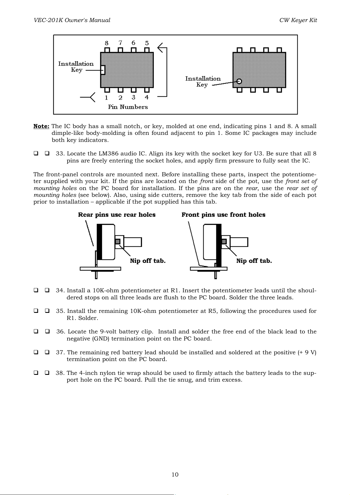
Integrated Circuits: Proper IC positioning is indicated by a dot or square marking located on one
end of the device. A corresponding mark will be silk-screened on the PC board and printed on the
kit's parts-placement diagram. To identify specific IC pin numbers for testing purposes, see the di-
agram below. Pin numbers always start at the keyed end of the case and progress counterclock-
wise around the device, as shown:
PARTS LIST
Your kit should contain all of the parts listed below. Please go through the parts bag to identify
and inventory each item on the checklist before you start building. If any parts are missing or
damaged, refer to the warranty section of this manual for replacement instructions. If you can't
positively identify an unfamiliar item in the bag on the basis of the information given, set it aside
until all other items are checked off. You may then be able to identify it by process of elimination.
Finally, your kit will go together more smoothly if parts are organized by type and arranged by val-
ue ahead of time. Use this inventory as an opportunity to sort and arrange parts so you can iden-
tify and find them quickly.
Qty Part Description Designation VEC P/N
5
0.1 µF disc ceramic capacitor
(labeled: .1 or 104)
3
10 µF electrolytic capacitor
5
0.01 µF disc ceramic capacitor
(labeled: .01 or 103)
1
220 µF electrolytic capacitor
1
1N4007 rectifier diode
2
3.5 mm stereo jack
1
RCA phono jack
1
2N7000 field-effect transistor
2
10K ohm potentiometer
2
15K ohm resistor
(code: brown-green-orange)
1
470 ohm resistor
(code: yellow-violet-brown)
1
10 ohm resistor
(code: brown-black-black)
2
DPDT push-action switch
1
78L05 5-volt regulator
1
PIC12C671 micro-controller IC
1
LM386 audio amplifier IC
2
8-pin IC sockets
1
9-volt battery clip with cord
1
VEC-201 circuit board
1
4-inch nylon tie wrap
1
Owner's Manual
C1, C2, C8, C9, C12
C3, C10, C11
C4, C5, C6, C7, C14
C13
D1
J1, J2
J3
Q1
R1, R5
R2,R3
R4
R6
SW1, SW2
U1
U2
U3
(For U2, U3)
200-3100
270-5100-1
200-2100
270-6220-1
300-4007
601-5005
600-0011
305-7000
153-4100-1
100-4150
100-2470
100-1100
504-0022
307-7805L
328-12671-1
324-0386
625-0008
730-3005
861-VEC201
745-2149
952-VEC201K
5
Page 8

VEC-201K Owner's Manual CW Keyer Kit
PARTS PLACEMENT DIAGRAM
STEP-BY-STEP ASSEMBLY
Before assembling your kit, please take time to read and understand the VEC kit warranty printed
on the inside cover of this manual. Also, read through the assembly instructions to make sure the
kit does not exceed your skill level. One you begin construction, your kit will be non-returnable.
Finally, if you haven't already done so, please verify that all parts listed in the inventory are in-
cluded. If anything is missing or broken, refer to the warranty instructions for replacing missing
or damaged parts.
Observe correct polarity when mounting components such as the electrolytic capacitors, diode,
transistor and voltage regulator. If you orient capacitors so their values face the board edges,
you'll be able to read them easily when the kit is finished. Part designators for components such
as R1, C3 etc., appear on the silk-screened legend on the component-mounting side of the printed
circuit board. These correspond to the drawing shown in the "Parts Placement Diagram" section of
this manual. The parts are inserted on the silk-screen side of the board. All capacitors should be
installed with their bodies as close to the PC board as possible; this is very important in RF cir-
cuits.
If you have last-minute questions about what you need to build your kit, please refer back to the
section titled "Before You Begin". If you're ready to begin now, here we go!
“Install” When you are directed to install a part, this means to locate, identify and insert the
part into its mounting holes on the PC board. This includes prebending or straightening leads as
needed so force is not required to seat the part. Once a component is mounted, bend each lead
over to hold it in place. Make sure trimmed leads don’t touch other pads and tracks, or a short
circuit may result:
6
Page 9

VEC-201K Owner's Manual CW Keyer Kit
“Solder” When you are directed to solder, this means to solder the part’s leads in place, and to in-
spect both (or all) solder connections for flaws or solder bridges. If no soldering problems are
noted, nip off the excess protruding leads with a sharp pair of side cutters.
Notice the directions use two sets of check boxes. Check one when a step is complete and use the
other for double-checking your work before operation.
Locate the five .01 µF ceramic disk capacitors (marked .01 or 103). Install and solder at the follow-
ing locations:
1. C4 .01 µF ceramic disk capacitor (.01 or 103)
2. C5 .01 µF ceramic disk capacitor (.01 or 103)
3. C6 .01 µF ceramic disk capacitor (.01 or 103)
4. C7 .01 µF ceramic disk capacitor (.01 or 103)
5. C14 .01 µF ceramic disk capacitor (.01 or 103)
Locate the five .1 µF ceramic disc capacitors (.1 or 104 marking). Install and solder at the follow-
ing locations:
6. C1 .1 µF (.1 or 104)
7. C2 .1 µF (.1 or 104)
8. C8 .1 µF (.1 or 104)
9. C9 .1 µF (.1 or 104)
10. C12 .1 µF (.1 or 104)
Resistor installation: The resistors packaged in this kit are all 5-percent tolerance ending with a
fourth gold color band, only the first three bands of the color code are needed for the following
steps. All resistor leads should be formed as shown below. Save the leads you cut off for upcoming
steps.
11. Find the 470-ohm resistor (yellow-violet-brown-gold). Install and solder at location R4.
12. Find the 10-ohm resistor (brown-black-black). Install and solder at location R6.
Find the two 15K ohm resistors (brown-green-orange). Install and solder at the following locations:
13. R2 15K ohm (brown-green-orange)
14. R3 15K ohm (brown-green-orange)
7
Page 10

VEC-201K Owner's Manual CW Keyer Kit
Select three scrap resistor lead ends for use as jumper wires, as shown below. Use needle-nose
pliers to form each one, making sure each rests flat on the PC board when installed:
14. Prepare, install and solder a wire jumper at JMP1.
15. Prepare, install and solder a second wire jumper at JMP2.
16. Prepare, install and solder a third wire jumper at JMP3.
Locate the 1N4007 silicon rectifier diode. Note that the band indicates the cathode lead end of the
device. Pre-form the leads in a similar manner as done for the resistors.
17. Install and solder the 1N4007 diode at location D1, be sure to observe the silk–
screened marking for the cathode lead orientation!
Locate the three 10-µF electrolytic capacitors. Install and solder at the following locations (observe
polarity):
18. C3 10 µF observe polarity markings.
19. C10 10 µF observe polarity markings.
20. C11 10 µF observe polarity markings.
21. Locate the 220-µF electrolytic capacitor, install and solder at location C13 (observe po-
larity).
Locate the 78L05 5 VDC voltage regulator. Form the leads as shown below to allow the device to
fit at location U1.
22. Install and solder the 78L05 at location U1.
23. Find the 2N7000 field-effect transistor. Position the body outline to correspond the
silk-screened legend at Q1. Install and solder.
24. Locate a push-action DPDT switch. Install at location SW1. The leads should be fully
seated, and the switch body level to the board. Solder.
8
Page 11

VEC-201K Owner's Manual CW Keyer Kit
25. Install the remaining push-action DPDT switch at location SW2. The leads should be
fully seated, and the switch body level to the board. Solder.
26. Switch SW2 must be changed from latching to momentary operation. Follow these di-
rections carefully to avoid damaging these switches! Set switch so shaft is latched in the
fully extended position. Using a pair of long-nose pliers, carefully lift the latching clip's
end near the switch body (away from the shaft) out of the switch assembly, and set it
to the side of the switch body as in the following diagram. Be careful not to remove the
end under the spring.
Locate the two 3.5 mm stereo jacks. Install and solder at the following board locations:
27. J1 3.5 mm stereo jack
28. J2 3.5 mm stereo jack
29. Find the RCA phono jack. Install and solder at location J3.
Locate the two 8-pin DIP integrated IC sockets. Note that the socket is “keyed” and should be in-
stalled with its key aligned to the silk-screened outline on the PC board.
30. Install and solder an 8-pin IC socket at location U2. Make sure key is orientated with
board legend.
31. Install and solder an 8-pin IC socket at location U3. Make sure key is orientated with
board legend.
32. Locate the PIC 12C671. Align its key (see following diagram)with the socket key for U2.
Be sure that all 8 pins are freely entering the socket holes, and apply firm pressure to
fully seat the IC.
9
Page 12
VEC-201K Owner's Manual CW Keyer Kit
Note: The IC body has a small notch, or key, molded at one end, indicating pins 1 and 8. A small
dimple-like body-molding is often found adjacent to pin 1. Some IC packages may include
both key indicators.
33. Locate the LM386 audio IC. Align its key with the socket key for U3. Be sure that all 8
pins are freely entering the socket holes, and apply firm pressure to fully seat the IC.
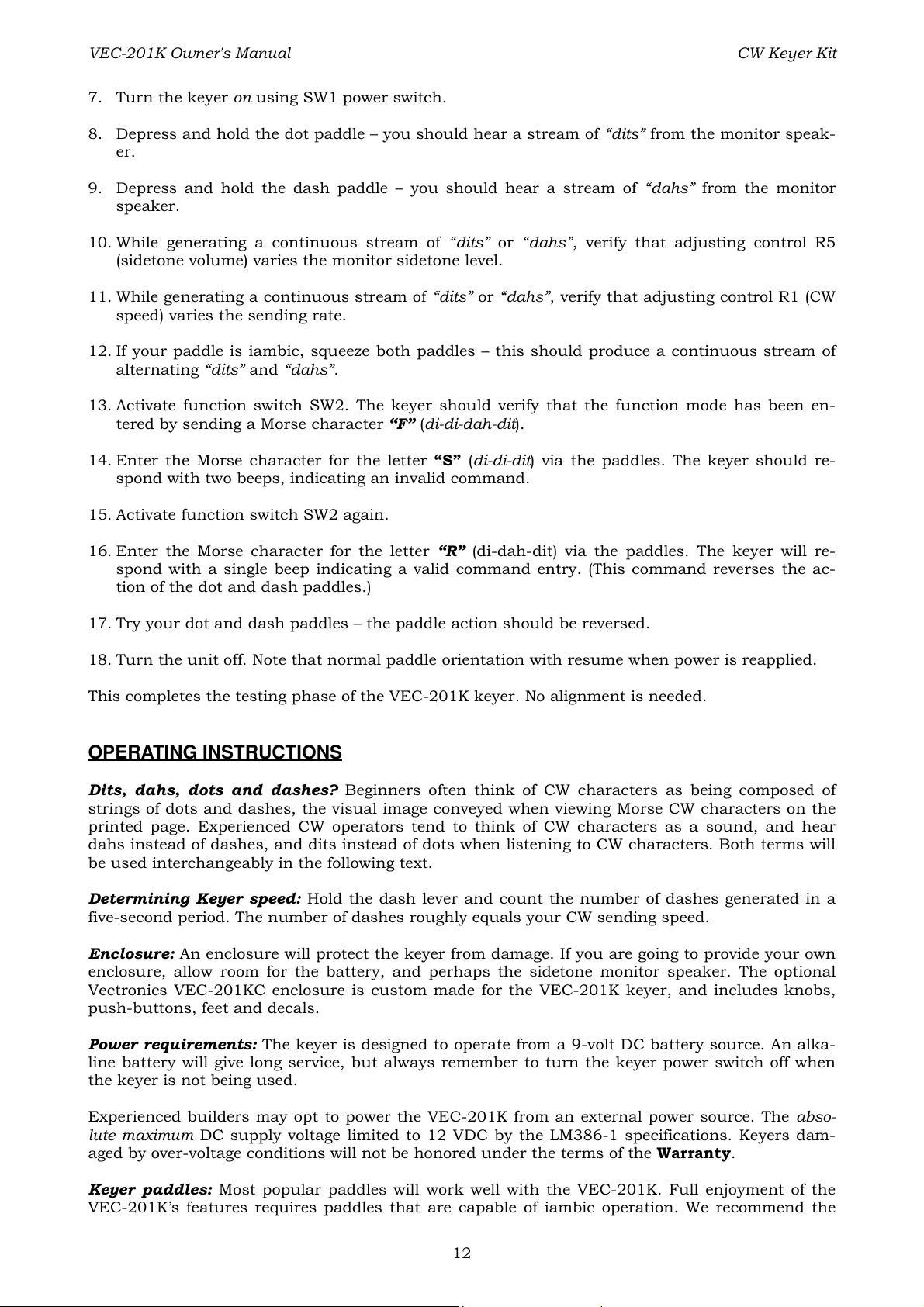
The front-panel controls are mounted next. Before installing these parts, inspect the potentiome-
ter supplied with your kit. If the pins are located on the front side of the pot, use the front set of
mounting holes on the PC board for installation. If the pins are on the rear, use the rear set of
mounting holes (see below). Also, using side cutters, remove the key tab from the side of each pot
prior to installation – applicable if the pot supplied has this tab.
34. Install a 10K-ohm potentiometer at R1. Insert the potentiometer leads until the shoul-
dered stops on all three leads are flush to the PC board. Solder the three leads.
35. Install the remaining 10K-ohm potentiometer at R5, following the procedures used for
R1. Solder.
36. Locate the 9-volt battery clip. Install and solder the free end of the black lead to the
negative (GND) termination point on the PC board.
37. The remaining red battery lead should be installed and soldered at the positive (+ 9 V)
termination point on the PC board.
38. The 4-inch nylon tie wrap should be used to firmly attach the battery leads to the sup-
port hole on the PC board. Pull the tie snug, and trim excess.
10
Page 13

VEC-201K Owner's Manual CW Keyer Kit
PC Board Inspection:
Before applying power to your kit, give it a thorough QC (quality control) inspection.
Compare parts locations against the parts-placement diagram. Was each part installed where
it is supposed to be? Was the correct value used? Start at one side of the board and work your
way across in an organized pattern.
Inspect the solder side of the board for cold-solder joins and solder bridges between tracks or
pads. Use a magnifying glass to obtain a clear view of the track area. If you suspect a solder
bridge, hold the board in front of a bright light for a better view. All joints should be smooth
and shiny, indicating good solder wetting and flow. Resolder any suspect connections.
Now that assembly and inspection is completed, you're ready to begin the testing and alignment
phase of construction.
TESTING AND ALIGNMENT
The following items will be needed for testing:
9-volt alkaline transistor battery.
Keyer paddles (iambic preferred), terminated with 3.5 mm stereo plug. Wired dot-to-tip, dash-
to-ring.
4 to 32-ohm headphones or monitor speaker, terminated with 3.5 mm plug.
Actuate push-action switch SW1 a few times and note the latching action. The switch will toggle
from off to on; the on condition exists when the shaft remains partially recessed; off when the
shaft is latched fully extended.
1. Set Power Switch SW1 to off.
2. Attach the paddle plug to jack J1 (key input) on the PC board.
3. Attach a monitor speaker or headphones to jack J2 (sidetone audio out.)
4. Preset control R5 (sidetone volume) to midrange.
5. Preset control R1 (speed) about 30% clockwise from the full counterclockwise stop.
6. Connect a fresh 9-volt battery to the battery clip.
11
Page 14
VEC-201K Owner's Manual CW Keyer Kit
7. Turn the keyer on using SW1 power switch.
8. Depress and hold the dot paddle – you should hear a stream of “dits” from the monitor speak-
er.
9. Depress and hold the dash paddle – you should hear a stream of “dahs” from the monitor
speaker.
10. While generating a continuous stream of “dits” or “dahs”, verify that adjusting control R5
(sidetone volume) varies the monitor sidetone level.
11. While generating a continuous stream of “dits” or “dahs”, verify that adjusting control R1 (CW
speed) varies the sending rate.
12. If your paddle is iambic, squeeze both paddles – this should produce a continuous stream of
alternating “dits” and “dahs”.
13. Activate function switch SW2. The keyer should verify that the function mode has been en-
tered by sending a Morse character “F” (di-di-dah-dit).
14. Enter the Morse character for the letter “S” (di-di-dit) via the paddles. The keyer should re-
spond with two beeps, indicating an invalid command.
15. Activate function switch SW2 again.
16. Enter the Morse character for the letter “R” (di-dah-dit) via the paddles. The keyer will re-
spond with a single beep indicating a valid command entry. (This command reverses the ac-
tion of the dot and dash paddles.)
17. Try your dot and dash paddles – the paddle action should be reversed.
18. Turn the unit off. Note that normal paddle orientation with resume when power is reapplied.
This completes the testing phase of the VEC-201K keyer. No alignment is needed.
OPERATING INSTRUCTIONS
Dits, dahs, dots and dashes? Beginners often think of CW characters as being composed of
strings of dots and dashes, the visual image conveyed when viewing Morse CW characters on the
printed page. Experienced CW operators tend to think of CW characters as a sound, and hear
dahs instead of dashes, and dits instead of dots when listening to CW characters. Both terms will
be used interchangeably in the following text.
Determining Keyer speed: Hold the dash lever and count the number of dashes generated in a
five-second period. The number of dashes roughly equals your CW sending speed.
Enclosure: An enclosure will protect the keyer from damage. If you are going to provide your own
enclosure, allow room for the battery, and perhaps the sidetone monitor speaker. The optional
Vectronics VEC-201KC enclosure is custom made for the VEC-201K keyer, and includes knobs,
push-buttons, feet and decals.
Power requirements: The keyer is designed to operate from a 9-volt DC battery source. An alka-
line battery will give long service, but always remember to turn the keyer power switch off when
the keyer is not being used.
Experienced builders may opt to power the VEC-201K from an external power source. The abso-
lute maximum DC supply voltage limited to 12 VDC by the LM386-1 specifications. Keyers dam-
aged by over-voltage conditions will not be honored under the terms of the Warranty.
Keyer paddles: Most popular paddles will work well with the VEC-201K. Full enjoyment of the
VEC-201K’s features requires paddles that are capable of iambic operation. We recommend the
12
Page 15

VEC-201K Owner's Manual CW Keyer Kit
Vectronics iambic paddles as being a good value. Iambic paddles can be recognized by the totally
independent operation of the Dit (or “Dot”) and Dah (or “Dash”) paddles. Some CW operators refer
to iambic paddles as “squeeze paddles”.
The paddles should be equipped with a three-wire interconnecting cable terminated in a 3.5 mm
stereo jack. Miniature shielded and balanced microphone cable is ideal for this. The common re-
turn is connected to the longest “ring” (shaft) of the stereo jack. The Dah paddle connection is
made to the jack terminal for the smaller insulated ring. The Dit paddle is connected to the jack
tip connection. If your paddles are equipped with a ¼” stereo jack, a suitable stereo adapter is
available at most electronic or Hi-Fi shops. Reversed paddle wiring can be corrected by a function
entry, more on this later. The paddles are connected to J1 on the VEC-201K.
3.5 mm stereo jack. Refer to the connector
packaging for wiring terminal details.
Linear controls: There are two linear controls. Potentiometer R5 sets the sidetone monitoring lev-
el. The second control, potentiometer R1, sets the CW speed over a range of 3 WPM (words-per-mi-
nute) to 65 WPM. This is for good reason, these are the controls that are most frequently adjusted.
Sidetone operation: The sidetone is tone keyed by the CW keyer. This permits you to monitor
your keying and provides the aural “feedback” to assist in sending good CW. Many transceivers al-
ready provide for internal CW sidetone monitoring. If your transmitter does not have built-in side-
tone monitoring provisions, the VEC-201K will generate a sidetone for you. Either a monitor
speaker (4 to 32 ohms) or headphones equipped with a 3.5 mm jack should be attached to J1 to
monitor the CW sidetone. Adjust potentiometer R5 (sidetone level) to a comfortable listening level.
Default initial status: As soon as power is supplied and the VEC-201K turned on by depressing
power switch SW1, the unit is ready for operation. A microprocessor program “subroutine” loads
several operating parameters into the keyer at power up. These parameters are based on standard
operating practices, many of them may be changed to suit your preferences – more on this later.
Commands entered via the function switch are cleared when the power is removed.
Initially, the keyer assumes standard paddle wiring, that is dit key to the tip, and dah key to the
ring of the 3.5 mm jack. Iambic operation is set to mode “A”. The sidetone frequency is set to 727
Hz. The CW weight is set to 50 %, yielding the standard 1:3 dit to dah ratio. The keyer is in the
automatic mode.
If CW operation is a new experience for you, consider running the keyer inits basic power-up con-
figuration until you become comfortable with its feel and operation. Feel free to learn the more ad-
vanced features at your own pace.
Default settings at power on:
1. 727 Hz sidetone.
2. Standard weight (50%, dot-dash-space ratio of 1:3:1)
3. Iambic A
4. Automatic
5. Standard paddle wiring (dot = tip, dash = ring)
13
Page 16

VEC-201K Owner's Manual CW Keyer Kit
Transmitter keying: The keyer output is through RCA phono jack J2. You will need a cable to
connect between the keyer and the CW keying jack of your radio. The operation instructions for
your set should show what sort of connector is needed and its location on your radio. Many mod-
ern transceivers use RCA phono jacks for connecting accessories, in those cases ready-made ca-
bles for home entertainment devices may be used between the VEC-201K and radio.
Keyer output specs: The keyer is designed for positive keying output. Most modern solid-state
transceivers and QRP transmitters meet this requirement. Always check the owner’s manual be-
fore attaching the keyer to a radio. The VEC-201K will key positive voltages to 50 VDC maximum.
Keying current is limited to 100 mA maximum. Exceeding these limits may damage keying tran-
sistor Q1.
Use with vintage sets: Early tube transmitters and hybrid transceivers may not be compatible
with the VEC-201K. If the transmitter uses grid-block keying (a negative key voltage), it can not be
used with the VEC-201K. An example of a grid-block keyed transmitter is the Heathkit DX60.
Check the ARRL handbooks for circuits for adapting keyers to grid-block keying.
Vintage novice transmitters commonly used cathode keying, a combination of high current and
high voltage. The Heathkit DX40 used cathode keying, for example. In general, most cathode-
keyed transmitters should be compatible with the VEC-201K keying circuit, so long as the 50
VDC and 100 mA limits are not exceeded.
Dot-and-dash memories and Iambic keying: The dot and dash memories make sending CW
easier. The memory allows the user to key a dot before the completion of a dash, and vica-versa.
This feature maybe checked by setting the keyer to the lowest speed and tapping first the dash
lever and then the dot lever before the completion of the dash. The keyer will generate a dash dot
with perfect spacing. Test the dash memory in a similar manner. First tap the dot lever, and be-
fore releasing quickly tap the dash lever. The keyer will send the dot followed by the dash, again
with perfect character spacing.
Iambic paddles allow both paddles (or levers) to be depressed at the same. Depressing (squeezing)
both paddles simultaneously will generate a continuous stream of alternating dots and dashes.
The first paddle contacted determines whether a dot or dash occurs first. CW characters such as
C, K, Q and R are very easily generated with iambic paddles.
Special Functions
Note: All programmable special functions are lost when the VEC-201K is turned off. The default
settings are restored at power on.
Automatic mode: Early telegraphers used a mechanical device called a bug to send high-speed-
code. The bug would automatically send a string of dits when the dot paddle was depressed and
held. Bugs did not generate strings of dashes, the dash had to be depressed once to generate each
individual “dah”. The VEC-201K normally operates in the fully automatic mode. However, it may
be set for “semi-automatic” operation, to emulate the sound and feel of a mechanical bug.
Weight: A 3:1 ratio between dit’s and dah’s is considered to be optimum. Some operators prefer
slightly different ratios; and the VEC-201K weight is adjustable from 25 to 75 % to suit those pref-
erences. The power-on default is 50 %, or 3:1.
Sidetone frequency: The default sidetone is about 727 Hz. The sidetone may be programmed
from 300 to 1000 Hz to suit individual tastes.
Reverse: Reverses the sense of the left and right paddles. Useful when the paddle is shared by
both left and right handed operators.
Iambic modes A and B: Either mode may be selected. A mode is default.
Using the function switch: The function switch customizes the keyer to your preferences. To set
or change a setting, depress the function switch. The keyer acknowledges by sending the Morse
CW character for the letter F (di-di-dahdit).
14
Page 17
VEC-201K Owner's Manual CW Keyer Kit
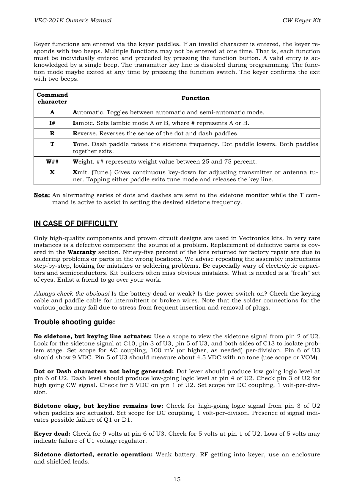
Keyer functions are entered via the keyer paddles. If an invalid character is entered, the keyer re-
sponds with two beeps. Multiple functions may not be entered at one time. That is, each function
must be individually entered and preceded by pressing the function button. A valid entry is ac-
knowledged by a single beep. The transmitter key line is disabled during programming. The func-
tion mode maybe exited at any time by pressing the function switch. The keyer confirms the exit
with two beeps.
Command
character
A Automatic. Toggles between automatic and semi-automatic mode.
I# Iambic. Sets Iambic mode A or B, where # represents A or B.
R Reverse. Reverses the sense of the dot and dash paddles.
T Tone. Dash paddle raises the sidetone frequency. Dot paddle lowers. Both paddles
together exits.
W## Weight. ## represents weight value between 25 and 75 percent.
X Xmit. (Tune.) Gives continuous key-down for adjusting transmitter or antenna tu-
ner. Tapping either paddle exits tune mode and releases the key line.
Note: An alternating series of dots and dashes are sent to the sidetone monitor while the T com-
mand is active to assist in setting the desired sidetone frequency.
Function
IN CASE OF DIFFICULTY
Only high-quality components and proven circuit designs are used in Vectronics kits. In very rare
instances is a defective component the source of a problem. Replacement of defective parts is cov-
ered in the Warranty section. Ninety-five percent of the kits returned for factory repair are due to
soldering problems or parts in the wrong locations. We advise repeating the assembly instructions
step-by-step, looking for mistakes or soldering problems. Be especially wary of electrolytic capaci-
tors and semiconductors. Kit builders often miss obvious mistakes. What is needed is a “fresh” set
of eyes. Enlist a friend to go over your work.
Always check the obvious! Is the battery dead or weak? Is the power switch on? Check the keying
cable and paddle cable for intermittent or broken wires. Note that the solder connections for the
various jacks may fail due to stress from frequent insertion and removal of plugs.
Trouble shooting guide:
No sidetone, but keying line actuates: Use a scope to view the sidetone signal from pin 2 of U2.
Look for the sidetone signal at C10, pin 3 of U3, pin 5 of U3, and both sides of C13 to isolate prob-
lem stage. Set scope for AC coupling, 100 mV (or higher, as needed) per-division. Pin 6 of U3
should show 9 VDC. Pin 5 of U3 should measure about 4.5 VDC with no tone (use scope or VOM).
Dot or Dash characters not being generated: Dot lever should produce low going logic level at
pin 6 of U2. Dash level should produce low-going logic level at pin 4 of U2. Check pin 3 of U2 for
high going CW signal. Check for 5 VDC on pin 1 of U2. Set scope for DC coupling, 1 volt-per-divi-
sion.
Sidetone okay, but keyline remains low: Check for high-going logic signal from pin 3 of U2
when paddles are actuated. Set scope for DC coupling, 1 volt-per-divison. Presence of signal indi-
cates possible failure of Q1 or D1.
Keyer dead: Check for 9 volts at pin 6 of U3. Check for 5 volts at pin 1 of U2. Loss of 5 volts may
indicate failure of U1 voltage regulator.
Sidetone distorted, erratic operation: Weak battery. RF getting into keyer, use an enclosure
and shielded leads.
15
Page 18

VEC-201K Owner's Manual CW Keyer Kit
Can’t enter function mode: Depressing SW2 should put a logic low on pin 5 of U2.
Keyer gives error beeps on function entry: Code characters must be perfectly formed, with
proper timing. Invalid command prefix or suffix.
THEORY OF OPERATION AND SPECIFICATIONS
Theory of operation:
The VEC-201K features the powerful PIC12C67x microcontroller. This tiny eight-pin integrated
circuit contains the programming and basic power of a microprocessor chip. CW speed is set via
R1, a 10K-ohm potentiometer, that controls the voltage input to pin 7 of U2 (PIC chip). Pin 7 is an
analog-to-digital input for the PIC processor. Programming subroutines scan the digitized setting
of R1, and adjust the speed accordingly.
Keyer paddle activation is also sensed by the PIC chip. All dot-and-dash memories, Iambic opera-
tions and sidetone generation and sidetone frequency are under the control of the PIC12C67x de-
vice.
Power to the PIC controller is regulated at 5 volts by IC U1, a low-power 5-VDC regulator IC. The
sidetone signal from the processor is amplified by U3, a linear audio amplifier IC. U3 is powered
directly from the 9-volt battery. Transistor Q1 is a silicon-gate TMOS switching FET, and is used
to key the transmitter. The maximum FET ratings are 50 VDC at 100 mA.
Specifications:
Voltage requirements ..................... Internal 9-volt transistor battery
Keyer speed ................................... Typically 3 to 65 WPM
Sidetone level ................................ 50 mW max., adjustable
Sidetone frequency ........................ 727 Hz default, adjustable 300 to 1000 Hz
Keying limits ................................. Positive keying. 50 volts at 100 mA max.
CW generation ............................... Iambic A or B, Automatic or Semi-automatic
Memory ......................................... Dot Dash memory
Weight ........................................... 50 % default, adjustable 25 to 75 percent
16
Page 19

VEC-201K Owner's Manual CW Keyer Kit
17
Page 20

VEC-201K Owner's Manual CW Keyer Kit
ENCLOSURE
Vectronics has designed a matching enclosure just for your VEC-201K CW Keyer Kit. The match-
ing enclosure is an all metal box which includes knobs, hardware, decals, and rubber feet. Enclo-
sure Model Number: VEC-201KC.
To install your keyer in the VEC-201KC matching enclosure follow these instructions (read all in-
structions before beginning ... take your time):
1. Find the front panel decal and rear panel decal; separate using scissors. Be sure to leave ex-
cess decal material around the edges. Put the rear panel decal on first. This is done by: a.) Re-
move all debris and oil from the chassis. This should be done using a piece of cloth and alco-
hol. b.) Remove the crack and peel to expose the adhesive. c.) Place the decal on the rear panel
without securing it completely. d.)Gently rub the alignment circles with your finger – if the
circles are centered in the enclosure holes (also check the corner alignment marks) secure the
decal by rubbing and removing all air bubbles. e.) If the alignment circles are not centered, ad-
just the decal accordingly then secure. f.) Use a pen knife, or small ExactoTM knife, to cut
away the unused edges (cut from the adhesive side) and cut out the component holes (cut
from the description side). g.) Repeat this procedure for the front panel.
2. Next, install the two L-brackets on the chassis using two of the 3/16" screws. The longer side
of the L-bracket must be connected to the chassis using the two holes centered on each edge
of the enclosure. Refer to the diagram on the next page for location and orientation.
3. Install the two 1/2" mounting screws next. Insert the screws, from the bottom, through the
two holes relatively close to each rear corner of the chassis.
4. Place the two 3/16" round spacers on the mounting screws.
5. Now insert the PC board. This must be done by: a.) Remove the nut and washer from R1 and
R5. b.) Insert the front of the PC board at an angle so the controls enter their respective holes.
c.) Push down on the rear of the board. Make sure the mounting screws align with the mount-
ing holes in the PC board before pushing.
6. Use the two hex nuts to secure the PC board. Be certain all appropriate components are cen-
tered with the enclosure holes before tightening. Put the washers and nuts – removed from R1
and R5 – back on and tighten.
7. Find the knobs and switch caps. Align the red switch cap with SW1 and push it on. If it is dif-
ficult to push on, then rotate it 90° and try again. Repeat for SW2 using the black switch cap.
Now put the knobs on R1 and R5. You may need to loosen the set screw. Align appropriately
then tighten the set screws.
8. Locate the piece of double-sided tape. This is to be used for holding the 9-volt battery clip in
place. Locate a place on the underside of the top cover where the battery will not interfere with
any components. Peel off the backing of the tape and stick it to the chosen location, then in-
stall the battery clip.
9. The top should be installed next. Use the two remaining 3/16" screws for securing the top to
the L-brackets. Make sure the L-brackets are aligned properly.
10. Finally, place the four rubber feet on the bottom of the enclosure at the corners.
18
Page 21

VEC-201K Owner's Manual CW Keyer Kit
19
 Loading...