

Page 1
VEC-1856 Instruction Manual 6 Meter Ground Plane Antenna
VEC-1856 6 METER GROUND PLANE ANTENNA
INTRODUCTION
The VEC-1856 Ground Plane Antenna features a DC grounded element and a ground
isolated radial system for improved performance.
The ground isolated radial system, unique to the VEC-1856 antenna, reduces undesirable
feedline and supporting structure radiation by eliminating common mode current paths.
This unique system improves transmission by producing a much cleaner pattern with
more signal at desired angles, and also reduces conducted noise reaching the antenna over
the outside of the feedline or antenna support. It also insures that the length of the
feedline or support does not change the antenna's resonant frequency or SWR.
The VEC-1856 is easily cut for the desired area of the six meter band. A rugged low
impedance air insulated matching stub provides convenient adjustment of base impedance
(a normal ground plane is much less than 50 ohms) allowing adjustment to a perfect 1:1
SWR. Power capability is 1000 watts RF continuous.
CHOOSING A LOCATION FOR THE ANTENNA
WARNING: Improper installation and assembly can be
hazardous! Read these instructions thoroughly
before attempting to assemble, install or operate
this product! Always mount this antenna so that
it is out of the reach of adults as well as
children. High power transmitting devices produce
voltages that can cause severe burns or other
injuries.
For the best performance on receiving and transmitting, mount this antenna in a clear
location at least a few feet above or 20 feet away from buildings, towers, feedlines, utility
wires, and other antennas. While your own ingenuity and particular circumstances will
determine the final mounting method, we will pass along some rules that can not be
neglected.
Never mount this antenna in a location that will permit unsuspecting people to come in
contact with the radials or any other part of the antenna.
Never mount this antenna where a mechanical failure might allow the antenna to contact
power lines or other utility wires.
Always ground the feed line at the point where it enters a building to a good earth ground
for lightning protection.
1
Page 2

VEC-1856 Instruction Manual 6 Meter Ground Plane Antenna
This antenna should be mounted on a rigid support. The mounting clamp supplied with
this antenna accepts masts between one and 1.5 inches outside diameter.
Tools required for assembly are:
• Hacksaw or Tubing Cutter
• 1-Phillips screwdriver
• 3/8" open end wrench
• 7/16" open end wrench
PARTS LIST
Note: All screws and nuts are stainless steel.
As you unpack this antenna, you should find the following items. Before attempting to
install this antenna, check the parts bag to insure that all hardware is accounted for. In the
event anything is missing, please contact Vectronics immediately.
1 VEC-1856 Instruction Manual
1 Antenna Base assembly
Parts Bag:
2 10-32 x 1" Phillips head bolts
2 10-32 stainless nuts
4 10-32 lock washers
1 10-32 nut
1 4-40 Phillips head screw
1 4-40 kep nut
2 2 1/2" x 1 3/4" Stainless steel plates
2 2 1/2" x 1 1/4" Fiberglass plates
1 U bolt assembly (2 nuts and 2 washers included)
2 plastic bushings
1 1/4" endcap
Rod Pack:
4 59 5/8" radials
1 54 3/4" radiator
1 Matching hairpin stub
2
Page 3
VEC-1856 Instruction Manual 6 Meter Ground Plane Antenna
ASSEMBLY PROCEDURE
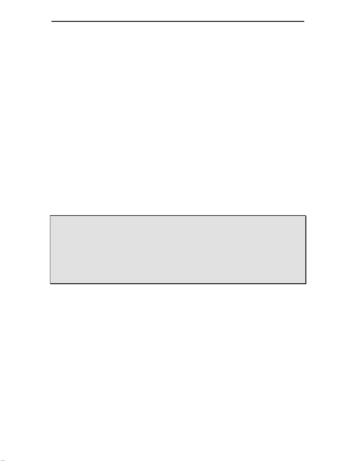
Locate the base of the antenna (Figure 1) to begin the assembly.
Figure 1 Antenna base.
Step 1:
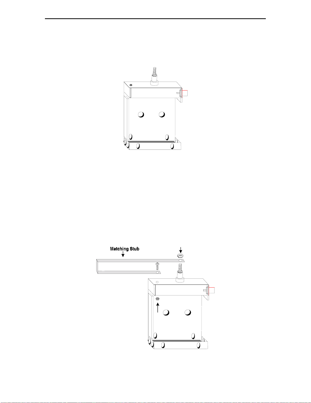
To attach the matching hairpin stub to the antenna base (Refer to Figure 2):
A. Place the longer end of the matching stub through the 10-32 screw that extends
through the ceramic insulating post on top of the antenna base. Thread the 10-32 nut
on the 10-32 screw and tighten with a 3/8" open end wrench. Do not over tighten..
B. Locate the hole on the top of the base and insert the 4-40 screw through the holes on
the short end of the matching stub and the antenna base. From the inside of the base,
thread the 4-40 kep nut on the screw and tighten. To tighten, hold the screw with the
1-Phillips screwdriver and hand tighten the nut.
.
Figure 2 Antenna base with Matching Stub attachment.
3
Page 4

VEC-1856 Instruction Manual 6 Meter Ground Plane Antenna
Step 2:
Insert a radial through the two rear most holes on the left and right sides of the bottom of
the base. Refer to Figure 3 and the holes labeled A. Push the radial through both holes
until one end extends 1/4 inch pass the second hole. Repeat this step for the two front
holes (labeled B) so that the two radials are protruding in opposite directions. Refer to
Figure 4 for an illustration of the radial assembly.
Step 3:
Insert a radial through the two left holes located on the front and rear of the base. Refer
to Figure 3 and the holes labeled C. Push the radial through both holes until one end
extends 1/4 inch pass the second hole. Repeat this step for the two holes on the right
(labeled D) so that the two radials are protruding in opposite directions (see Figure 4).
Figure 3 Antenna base with holes labeled.
: The two radials that are placed in holes A and B are inserted in the base before the
Note
radials that are placed in holes C and D.
4
Page 5

VEC-1856 Instruction Manual 6 Meter Ground Plane Antenna
Step 4:
Insert the plastic bushings into each of the 1/2" round holes in the back of the antenna
base. The bushings are to remain flush with the base on both sides. See Figure 4.
Figure 4 Antenna base with radial assembly.
Step 5:
With the radials in place, stack the two st ainless steel pl ates together and place them over
the radials in t he bottom of the antenna base. See Figure 5. Place one lock washer on
each of the 10-32 Phillips head bolts. Secure the elements by inserting the 10-32 bolts
through the bottom of the base then through the plates. Thread the lock washers and 1032 stainless nuts on the bolts. Tighten by using the Phillips screwdriver to hold the bolts
and the 3/8" open end wrench to tighten the kep nuts.
5
Page 6

VEC-1856 Instruction Manual 6 Meter Ground Plane Antenna
Figure 5 Antenna base with stainless steel plate assembly shown.
Step 6:
To install the antenna to your mast:
A. Remove the nuts, washers and saddle from the U bolt. See Figure 6.
Figure 6 U bolt assembly.
B. Place the U bolt around the mast (not included) and install the saddle on the U bolt.
Be sure the saddle is in the correct position to "bite" into the mast.
C. Slide one of the fiberglass plates on the U bolt until it is against the saddle. Insert the
U bolt through the plastic bushings on the back of the base. Be sure the plastic
bushings remain in place. See Figure 7.
6
Page 7

VEC-1856 Instruction Manual 6 Meter Ground Plane Antenna
Figure 7 U bolt assembly with fiberglass plates.
D. Install the other fiberglass plate through the U bolt from the front of the antenna base.
Place the lock washers over the U bolt and hand thread the nuts on the bolt. Tighten
the nuts securely with the 7/16" open end wrench to ensure that the antenna does not
slip. Do not over tighten. See Figure 8.
Figure 8 Final antenna assembly.
7
Page 8

VEC-1856 Instruction Manual 6 Meter Ground Plane Antenna
TUNING THE ANTENNA
After the antenna base with radials has been secured to the mast, refer to Chart 1 to tune
the antenna to the desired frequency. Locate the radiator. This is the 54 3/4" hollow tube
that is threaded on the inside at one end. The radiator length is factory set for 50 Mhz.
To tune the antenna to other frequencies, cut the radiator with a hacksaw or tubing cutter.
Do not cut the radi ator at the threaded end! Once t he radiator has been cut the change is
permanent!
Chart 1 Cutting measurements for tuning between 50 and 54 Mhz.
FREQUENCY RADIATOR LENGTH CUT LENGTH
50 Mhz 54 3/4 INCHES 0 INCHES
51 Mhz 52 7/8 INCHES 1 7/8 INCHES
52 Mhz 51 INCHES 3 3/4 INCHES
53 Mhz 49 1/8 INCHES 5 5/8 INCHES
54 Mhz 47 1/4 INCHES 7 1/2 INCHES
After cutting the radiator for the desired frequency, place the 1/4" endcap over the end
that is not threaded. This will prevent the antenna radiator from becoming filled with rain
water. Attach the radiator to the antenna base by hand threading the radiator over the 1032 screw on the top of the base as shown in Figure 9.
Figure 9 Antenna with radiator attached.
After cutting the radiator to the correct length, adjust for lowest SWR by squeezing or
spreading the center of the matching stub.
8
Page 9

VEC-1856 Instruction Manual 6 Meter Ground Plane Antenna
BALUN
In order to prevent unwanted radiation from the feedline, we suggest installing a balun at
the feedpoint. This need not be an elaborate or expensive addition--you can make a
simple and effective choke-type balun using the feedline itself. Below are three examples
of how to do this:
1. Form a 5-turn coil (about 3 to 6" in diameter) of coax just below the feedpoint using
about 6' of cable. Tape the coils together tightly with electrical tape and secure them
to the mast.
2. Install a 5" total length of 43 mix ferrite core on the feedline at the feedpoint. Be sure
to secure your feedline to the mast with electrical tape to provide stress relief at the
feedpoint.
3. Using a metallic mast, from the feedpoint keep the coax 3 to 4" from the mast for 50".
Use an insulator (PVC pipe) if necessary. Below the 50" air spaced length tape the
coax to the mast and keep the coax taped against the mast for at least three feet.
TECHNICAL ASSISTANCE
If you have any problem with this unit first check the appropriate section of this manual.
If the manual does not reference your problem or your problem is not solved by reading
the manual, you may call Vectronics at 601-323-5800. You will be best helped if you
have your unit, manual and all information on your station handy so you can answer any
questions the technicians may ask.
You can also send questions by mail to Vectronics, 1007 HWY 25 South, Starkville, MS
39759; or by Facsimile (FAX) to 601-323-6551. Send a complete description of your
problem, an explanation of exactly how you are using your unit, and a complete
description of your station.
9
 Loading...