

Page 1

IMPORTANT WARRANTY INFORMATION! PLEASE READ
Return Policy on Kits When Not Purchased Directly From Vectronics: Before continuing
any further with your VEC kit check with your Dealer about their return policy. If your Dealer
allows returns, your kit must be returned before you begin construction.
Return Policy on Kits When Purchased Directly From Vectronics: Your VEC kit may be
returned to the factory in its pre-assembled condition only. The reason for this stipulation is,
once you begin i nsta lli ng a nd sol deri ng pa rt s, you essenti al ly tak e over the rol e of the devic e's
manufacturer . From this point on, neither Vect ronics nor its dea lers can reas onably be held
accountab le for the qua lity or the outcome of your work. Because of this, Vectronics cannot
accept return of any kit-in-progress or completed work as a warranty item for any reason
whatsoever. If you are a new or inexperienced kit b uilder, we urge you to read the manual
carefully a nd determine whether or not you're r eady to tak e on the job. If you wish to c hange
your mind and return your ki t, you may--b ut you must do i t before you begin c ons tr uc ti on, a nd
within ten (10) working days of the time it arrives.
Vectronics Warrants: Your kit contains each item specified in the parts list.
Missing Parts: If you determine, during your pre-construction inventory, that any part is
missing, please contact Vectronics and we'll send the missing item to you free of charge.
However, before you contact Vect ronic s, please look carefully to c onf ir m you haven't misr ea d
the marking on one of the other items provided with the kit. Also, make certain an alternative
part hasn't been substituted for the item you're missing. If a specific part is no longer
available, or if Engineering has determined that an alternative component is more suitable,
Vectronics reserves the right to make substitutions at any time. In most cases, these changes
will be clearly noted in an addendum to the manual.
Defective Parts: Today's electronic parts are physically and electrically resilient, and
defective components a re r a re. However, if you disc over a n it em duri ng your pr e- c onst r uct i on
inventory that's obviously broken or unserviceable, we'll replace it. Just return the part to
Vectronics at the address below accompanied with an explanation. Upon receipt, we'll test it.
If it's defec tive and appear s unused, we'll ship you a new one right away at no charge.
Missing or Defective Parts After You Begin Assembly: Parts and materials lost or
damaged after construction begins are not covered under the terms of this warranty. However,
most parts supplied with VEC kits are relatively inexpensive and Vectronics can replace them
for a reasonable charge. Simply contact the factory with a complete description. We'll
process your order quickly and get you back on trac k.
Factory Repair After You Begin Assembly: Kits-in progress and completed kits are
specifically excluded from coverage by the Vectronics warranty. However, as a service to
customers, tec hnicia ns ar e availa ble t o evaluate a nd repai r malf unctioni ng kits for a minimum
service fee of $18.00 (½ hour rate) plus $7.00 shipping and handling (prices subject to
change). To qualify for repair service, your kit must be fully completed, unmodified, and the
printed circuit board assembled using rosin-core solder. In the event your repair will require
more than an hour to fi x (or $36.00, subject to change), our technicians will contact you in
advance by telephone b efore p erforming t he work. Def ective unit s should b e shipp ed prep aid
to:
Vectronics
300 Industrial Pa rk Road
Starkville, MS 39759
Page 2

When shipping, pack your kit well and include the minimum payment plus shipping and
handling charges ($25.00 total). No work can be performed without pre-payment. Also,
provide a valid UPS return address a nd a day time phone number where you may be reac hed.
Page 3

VEC-1604K Owner's Manual Portable CD Amplifier Kit
INTRODUCTION
General Information:
hall ambiance and bone-rattling realism to private listening. However, there are
times when headphone isolation and dangling cords makes it difficult to carry on
a conversation, share the music, hear the phone ring, or perform other activities.
This great little CD amp helps you get beyond that limitation, extending the
usefulness of your player and turning it into a mini-stereo system. Use it in your
dorm room, at the beach, on the patio, in the workshop--anywhere a full-sized
stereo can't be found! Circuitry uses two high-quality amplifier ICs--just like
those used in car stereo systems. You'll love the full-bodied sound this project
delivers!
Circuitry:
ICs (one per channel). Each IC provides both a pre-amp and power amp to
boost weak headphone level signals up to robust speaker levels. Volume for
each channel is controlled individually to maintain stereo balance, while tone is
set by a single control. Use a 12-volt battery, automotive electrical system, or
AC power-adapter--and DC source from 12 to 24 Volts--to run your amp.
Works with any 8 to 16-Ohm speaker system capable of handling at least 4
Watts RMS per channel.
Your VEC-1604K uses two (2) TDA1013 4-Watt monolithic audio
Personal CD players are famous for bringing concert-
TOOLS AND SUPPLIES
Construction Area:
area where you can easily organize and handle small parts without losing them.
An inexpensive sheet of white poster board makes an excellent construction
surface, while providing protection for the underlying table or desk. Diffused
overhead lighting is a plus, and a supplemental high-intensity desk lamp is
especially helpful for close-up work. Safety is always important! Use a suitable
high-temperature stand for your soldering iron, and keep the work area free of
clutter.
Kit construction requires a clean, smooth, and well-lighted
Universal Kit-building Tools:
kit beyond common items normally used for bench construction. We
recommend the following:
!
Soldering Iron (grounded-tip and temperature-controlled preferred)
!
High-temperature Iron Holder with Cleaning Sponge
!
Solder, 60/40 or 37/63 with rosin or "no-clean" flux (.031" dia. is good
size).
!
Needle Nose Pliers or Surgical Hemostats
No special tools are required to complete this
1
Page 4

VEC-1604K Owner's Manual Portable CD Amplifier Kit
!
Diagonal Cutters or "Nippy Cutters"
!
Solder Sucker (squeeze or vacuum pump type), or Desoldering Braid
!
Bright Desk Lamp
!
Magnifying Glass
BEFORE YOU START BUILDING
Experience shows there are four common mistakes builders make. Avoid these,
and your kit will probably work on the first try! Here's what they are:
1. Installing the Wrong Part:
and a 10K resistor may look almost the same, but they may act very
differently in an electronic circuit! Same for capacitors--a device marked
102 (or .001 uF) may have very different operating characteristics from one
marked 103 (or .01uF).
2. Installing Parts Backwards:
capacitors to make sure the positive (+) lead goes in the (+) hole on the
circuit board. Transistors have a flat side or emitter tab to help you identify
the correct mounting position. ICs have a notch or dot at one end indicating
the correct direction of insertion. Diodes have a banded end indicating
correct polarity. Always double-check--especially before applying power to
the circuit!
3. Faulty Solder Connections:
bridges. Cold solder joints happen when you don't fully heat the connection-or when metallic corrosion and oxide contaminate a component lead or pad.
Solder bridges form when a trail of excess solder shorts pads or tracks
together (see Solder Tips below).
4. Omitting or Misreading a Part:
Always double-check to make sure you completed each step in an assembly
sequence.
Soldering Tips:
professional soldering. Before you install and solder each part, inspect leads or
pins for oxidation. If the metal surface is dull, sand with fine emery paper until
shiny. Also, clean the oxidation and excess solder from the soldering iron tip to
ensure maximum heat transfer. Allow the tip of your iron to contact both the
lead and pad for about one second (count "one-thousand-one") before feeding
solder to the connection. Surfaces must become hot enough for solder to flow
smoothly. Feed solder to the opposite side of the lead from your iron tip--solder
will wick around the lead toward the tip, wetting all exposed surfaces. Apply
Cleanliness and good heat distribution are the two secrets of
It always pays to double-check each step. A 1K
Always check the polarity of electrolytic
Inspect for cold-solder joints and solder
This is easier to do than you might think!
2
Page 5
VEC-1604K Owner's Manual Portable CD Amplifier Kit
solder sparingly, and do not touch solder directly to the hot iron tip to promote
rapid melting.
Desoldering Tips:
these instructions carefully! First, grasp the component with a pair of hemostats
or needle-nose pliers. Heat the pad beneath the lead you intend to extract, and
pull gently. The lead should come out. Repeat for the other lead. Solder may
fill in behind the lead as you extract it--especially if you are working on a
double-sided b o ar d with plat e-thr o ugh hol es. Sho uld this ha pp e n, tr y heat ing the
pad again and inserting a common pin into the hole. Solder won't stick to the
pin's chromium plating. When the pad cools, remove the pin and insert the
correct component. For ICs or multi-pin parts, use desoldering braid to remove
excess solder before attempting to extract the part. Alternatively, a low-cost
vacuum-bulb or spring-loaded solder sucker may be used. Parts damaged or
severely overheated during extraction should be replaced rather than reinstalled.
Work Habits:
instructions and, in many cases, to perform new and unfamiliar tasks. To avoid
making needless mistakes, work for short periods when you're fresh and alert.
Recreational construction projects are more informative and more fun when you
take your time. Enjoy!
Sorting and Reading Resistors:
a color code (shown below). You don't have to memorize this code to work with
resistors, but you do need to understand how it works:
If you make a mistake and need to remove a part, follow
Kit construction requires the ability to follow detailed
The electrical value of resistors is indicated by
Resistor Color Code
Blue = 6
Violet = 7
Gray = 8
White = 9
Silver = 10%
Gold = 5%
1st Digit
2nd Digit
Multiplier
Tolerence
(gold or silver)
Black = 0 (tens)
Brown = 1 (hundreds)
Red = 2 (K)
Orange = 3 (10K)
Yellow = 4 (100K)
Green = 5 (1Meg)
When you look at a resistor, check its multiplier code first. Any resistor with a
black multiplier band falls between 10 and 99 ohms in value. Brown designates
a value between 100 and 999 ohms. Red indicates a value from 1000 to 9999
ohms, which is also expressed as 1.0K to 9.9K. An orange multiplier band
designates 10K to 99K, etc. To sort and inventory resistors, first separate them
into groups by multiplier band (make a pile of 10s, 100s, Ks, 10Ks, etc.). Next,
sort each group by specific value (1K, 2.2K, 4.7K, etc.). This procedure makes
the inventory easier, and also makes locating specific parts more convenient later
3
Page 6
VEC-1604K Owner's Manual Portable CD Amplifier Kit
on during construction. Some builders find it especially helpful to arrange
resistors in ascending order along a strip of double-sided tape.
Reading Capacitors:
Unlike resistors, capacitors no longer use a color code for
value identification. Instead, the value, or a 3-number code, is printed on the
body.
Value Code
10 pF = 100
100 pF = 101
1000 pF = 102
.001 uF = 102*
.01 uF = 103
.1 uF = 104
Multilayer
(270 pF)
271
Ceramic Discs
(.001 uF) (.1 uF)
102
104
Electrolytic
1 uF
1uF
|
35V
|
+
-
As with resistors, it's helpful to sort capacitors by type, and then to arrange them
in ascending order of value. Small-value capacitors are characterized in pF (or
pico-Farads), while larger values are labeled in uF (or micro-Farads). The
transition from pF to uF occurs at 1000 pF (or .001 uF)*. Today, most
monolithic and disc-ceramic capacitors are marked with a three-number code.
The first two digits indicate a numerical value, while the last digit indicates a
multiplier (same as resistors).
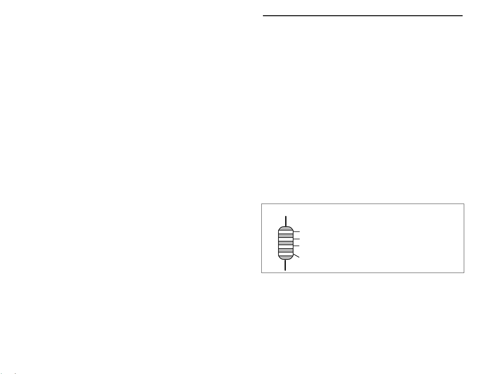
Electrolytic capacitors are always marked in uF. Electrolytics are polarized
devices and must be oriented correctly during installation. If you become
confused by markings on the case, remember the uncut negative lead is slightly
shorter than the positive lead.
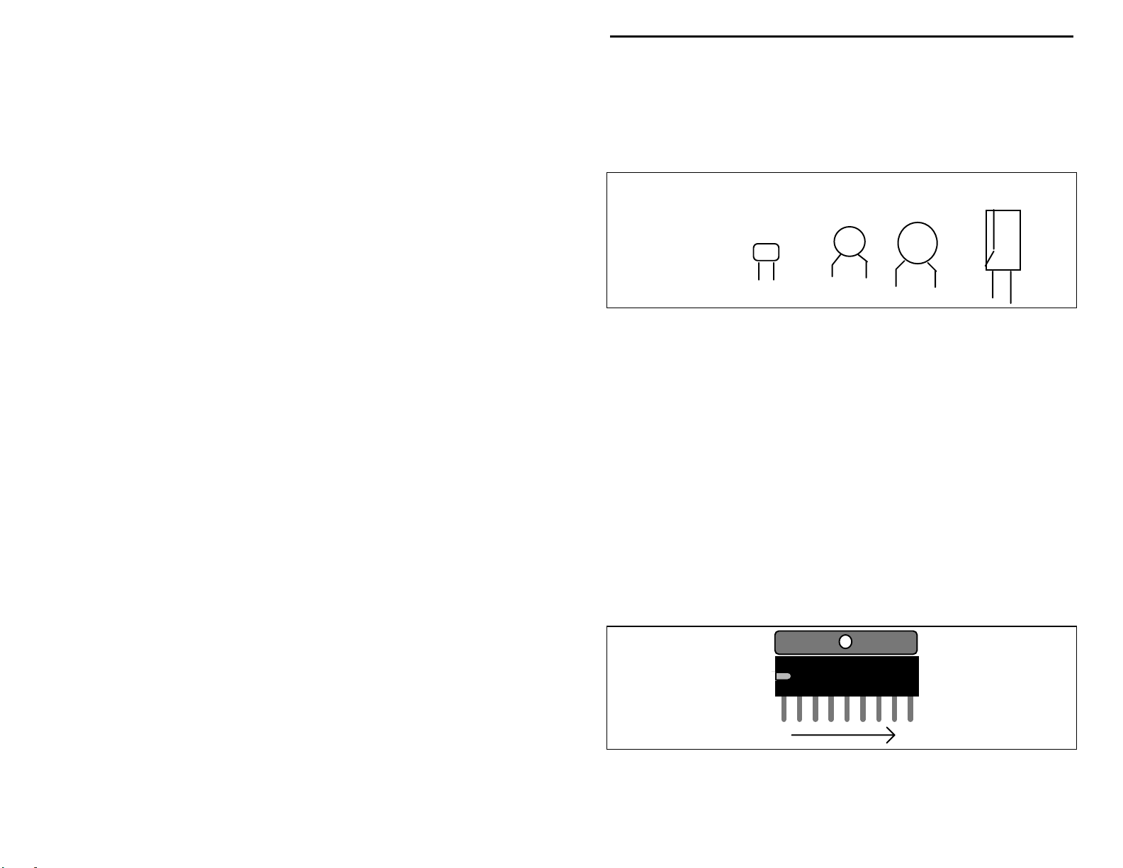
Integrated Circuits:
Proper IC positioning is indicated by a dot or square
marking located on one end of the device. A corresponding mark will be silkscreened on the PC board and printed on the kit's parts-placement diagram. To
identify specific IC pin numbers for testing purposes, see the diagram below.
Pin numbers always begin at "1" at the keyed end of the case and progress along
the device, as shown:
TDA1013B
19
4
Page 7

VEC-1604K Owner's Manual Portable CD Amplifier Kit
PARTS LIST
Your kit should contain all of the parts listed below. Please identify and
inventory each item on the checklist before you start building. If any parts are
missing or damaged, refer to the manual's warranty section for replacement
instructions. If you can't positively identify an unfamiliar item on the basis of the
information given, set it aside until all other items are checked off. You may
then be able to identify it by process of elimination. Finally, your kit will go
together more smoothly if parts are organized by type and arranged by value
ahead of time. Use this inventory as an opportunity to sort and arrange parts so
you can identify and find them quickly.
"
Qty Part Description Designation VEC P/N
!
2 1.5 ohm resistor (brn-grn-gold) R9,R10 100-0150
!
2 1K ohm resistor (brn-blk-red) R11,R12 100-3100
!
2 5.1K ohm resistor (grn-brn-red) R4,R6 100-3510
!
2 51K ohm resistor (grn-brn-org) R3,R5 100-4510
!
2 100K ohm resistor (brn-blk-yel) R7,R8 100-5100
!
2 10K potentiometer (B10K) R1,R2 153-4100-1
!
1 500K dual potentiometer (B504) R13 153-5500-12
!
3 .1 uF disc ceramic capacitor (104) C7,C8,C13 200-3100-1
!
2 10 uF electrolytic capacitor C9,C10 270-5100-1
!
2 470 uF electrolytic capacitor C11,C12 270-6470-1
!
2 .0068 uF multilayer capacitor C1,C3 220-1680
!
2 .047 uF multilayer capacitor C2,C4 220-2470
!
2 .33 uF multilayer capacitor C5,C6 220-3330B
!
1 TDA1013B IC U1,U2 324-1013
!
1 DPDT push-button switch SW2 504-2022
!
3 3.5mm stereo jack J1,J2,J3 601-5005
!
1 2.1mm coaxial-type jack J4 601-6121B
!
1 2" length of insulated wire (red) 871-2400-1200
!
2 12" length of insulated wire 871-2422-0200
!
1 VEC-1604 pc board 861-VEC1604
!
1 Owner's manual 925-VEC1604K
5
Page 8

Page 9

VEC-1604K Owner's Manual Portable CD Amplifier Kit
! !
1. Install a 1.5 ohm resistor at R9 and solder.
! !
2. Install a 1.5 ohm resistor at R10 and solder.
Find two (2) 1K resistors (brown-black-red).
! !
3. Install a 1K resistor at R11 and solder.
! !
4. Install a 1K resistor at R12 and solder.
Find two (2) 5.1K resistors (green-brown-red).
! !
5. Install a 5.1K resistor at R4 and solder.
! !
6. Install a 5.1K resistor at R6 and solder.
Find two (2) 51K resistors (green-brown-orange).
! !
7. Install a 51K resistor at R3 and solder.
! !
8. Install a 51K resistor at R5 and solder.
Find two (2) 100K resistors (brown-black-yellow).
! !
9. Install a 100K resistor at R7 and solder.
! !
10. Install a 100K resistor at R8 and solder.
This completes installation of the 10 fixed-value resistors (three variable
resistors will be installed later). Take a moment to confirm each one is
positioned in the right location on the PC board.
Now is a good time to install JMP1. Use a clipped resistor lead to make this
jumper.
! !
11. Install a jumper wire at JMP1. The wire should lay on top of the text
"JMP1".
Next, we'll install the kit's 13 capacitors--starting with the disc-ceramic types.
Find three (3) .1 uF disc ceramic capacitors (marked 104).
! !
12. Install a .1 uF capacitor at C7 and solder.
! !
13. Install a .1 uF capacitor at C8 and solder.
! !
14. Install a .1 uF capacitor at C13 and solder.
There are 6 multilayer capacitors provided with your kit. A multilayer capacitor
is similar to a surface-mount "chip" capacitor, except that it has a lead spotwelded onto each end of the capacitor body. Multilayers are very small and take
up less space than other capacitor types. However, lead welds may fail if the
device is over-stressed during installation or removal. For this reason, never use
7
Page 10

VEC-1604K Owner's Manual Portable CD Amplifier Kit
force to seat a multilayer capacitor into the PC board. If the spacing isn't right,
pre-form the leads to the correct spacing before installation!
Find two (2) .0068 uF multilayer capacitors (marked 682).
! !
15. Install a .0068 uF capacitor at C1 and solder.
! !
16. Install a .0068 uF capacitor at C3 and solder.
Find two (2) .047 uF multilayer capacitors (marked 473).
! !
17. Install a .047 uF capacitor at C2 and solder.
! !
18. Install a .047 uF capacitor at C4 and solder.
Find two (2) .33 uF multilayer capacitors (marked 334).
! !
19. Install a .33 uF capacitor at C5 and solder.
! !
20. Install a .33 uF capacitor at C6 and solder.
This completes installation of the 6 multilayer caps.
The last (4) capacitors in your kit are electrolytic.
polarized and must be installed the correct way in order to work.
capacitor's plus (+) mounting holes are noted on both the circuit board and parts
placement diagram. If the markings on the capacitor body are unclear, the plus
(+) lead is always the longer of the two.
Find two (2) 10 uF electrolytic capacitors. Identify the (+) lead on each.
! !
21. Install a 10 uF capacitor at C9 and solder.
! !
22. Install a 10 uF capacitor at C10 and solder.
Find two (2) 470 uF electrolytic capacitors. Identify the (+) lead on each.
! !
23. Install a 470 uF capacitor at C11 and solder.
! !
24. Install a 470 uF capacitor at C12 and solder.
This completes installation of all capacitors. Before moving on to the next phase
of construction, check the polarity of each electrolytic one more time to confirm
all four are installed correctly.
The front-p anel controls (volume & tone ) are mounted next. Before installing
these parts, inspect the type of potentiometer supplied with your kit. If the pins
are located on the front side of the pot, use the front set of mounting holes on the
PC board for installation. If the pins are on the rear, use the rear set of
mounting holes (see the following diagram). Also, using side cutters, remove the
key tab from the side of each pot prior to installation.
Electrolytic caps are
Each
8
Page 11

VEC-1604K Owner's Manual Portable CD Amplifier Kit
Rear pins use rear holes.
Nip off tab.
Find two (2) 10K potentiometers (marked B10K or B103K). Inspect for pin
location (as described previously) and locate the appropriate mounting holes on
the PC board.
! !
25. Install a 10K pot at R1 and solder.
! !
26. Install a 10K pot at R2 and solder.
Find the dual-section 500K pot (marked B504K). No alternative pin locations
are provided for this style control.
! !
27. Install the dual-section 500K pot at R13 and solder.
Your kit contai ns a miniature DPDT switch. Some versions require installation
of a plastic clip-on support at the front of the switch body. This piece relieves
stress on the pins and ensures level seating during installation. If your parts kit
contains this piece, install as shown:
Front pins use front holes.
Nip off tab.
Your switch should also have a red cap supplied with it. Install this on the pushbutton shaft. Once the switch is prepared for installation:
! !
28. Install the DPDT mini switch at SW2 and solder.
The two last PC board mounted components are the AF amplifier ICs, U1 and
U2. Find these devices (marked TDA1013B). Before installing, inspect both
carefully and straighten any bent or crooked pins. Use extreme care during IC
pin insertion and move slowly. It's easy to miss a mounting hole and fold a pin
underneath the body.
9
Page 12

VEC-1604K Owner's Manual Portable CD Amplifier Kit
! !
29. Find a TDA1013B and identify its keyed end. Now, find the mounting
holes for U1 and identify the keyed end on the silkscreen pattern.
Align U1 so it corresponds with the silkscreen pattern and insert,
checking carefully that all 9 pins enter their respective mounting holes.
Solder all 9 pins.
! !
30. Repeat the above procedure, installing a TDA1013B at U2. Solder all
9 pins.
Installing the amplifier's power and audio connectors involves point-to-point
wiring, where you'll prepare and install installed wires connecting the jacks to
the PC board. Find the hookup wire provided with your kit. After cutting each
wire to its specified length, prepare it for installation by removing 1/4" of
insulation from each end.
Locate a 12" length of insulated wire:
! !
31. Cut and prep a 2-1/2" length of insulated wire. Install one end at
GND4 and solder.
! !
32. Cut and prep a 3" length of insulated wire. Install one end at GND3
and solder.
! !
33. Cut and prep a 4" length of insulated wire. Install one end at GND2
and solder.
! !
34. Cut and prep a 2" length of insulated wire. Install one end at GND1
and solder.
! !
35. Locate the 2" length of red wire. Install one end at PWR and solder.
Locate three (3) 3.5-mm stereo jacks. Find the common (or GND) terminal
using the following diagram. Follow the installation detail when connecting
leads to jacks.
Bottom View
Ring
Tip
Common (GND)
Wrap lead-end around pin
and solder in place.
The first connector you'll install is the Left-Channel Speaker Jack:
! !
36. Find the 2-1/2" insulated wire connected to GND4. Solder the free
end to the common or GND tab on a 3.5-mm stereo jack.
! !
37. Cut and prep a 2-1/2" length of insulated wire. Connect one end to LOUT and solder.
10
Page 13

VEC-1604K Owner's Manual Portable CD Amplifier Kit
! !
38. Connect the free end of the insulated wire from L-OUT to the TIP tab
on the jack.
Next, install the Right-Channel Speaker Jack:
! !
39. Find the 3" length of insulated wire connected to GND3. Solder the
free end to the common or GND tab on a 3.5-mm stereo jack.
! !
40. Cut and prep a 4" length of insulated wire. Connect one end to ROUT and solder.
! !
41. Connect the free end of the insulated wire from R-OUT to the TIP tab
on the jack.
Finally, install the CD-Player Stereo Input connector.
! !
42. Find the 4" length of insulated wire connected to GND2. Solder the
free end to the common or GND tab on the last 3.5-mm stereo jack.
! !
43. Cut and prep a 3-1/2" length of insulated wire. Connect one end to LIN and solder.
! !
4 4. Connect the free end of the insulated wire from L-IN to the TIP tab
and solder.
! !
45. Cut and prep a 2" length of insulated wire . Connect one end to R-IN
and solder.
! !
46. Connect the free end of the insulated wire from R-IN to the RING tab
and solder (see diagram).
If you have the companion VEC-1604KC cabinet kit, you'll mount the 2.1-mm
power jack in the panel prior to connecting the power leads to from the PC
board. If you plan to install your kit in a different box, go ahead and install the
power jack at this time so you can test your unit. The power jack has three
solder tabs on the back, as shown below:
red (+)
black (-)
! !
47. Find the 2" red wire connected to PWR. Connect the free end to the
(+) tab of the power jack, as shown. Solder.
! !
48. Find the 2-1/2" length of insulated wire connected to GND1. Connect
the free end to the (-) tab of the power jack, as shown. Solder.
11
Page 14

VEC-1604K Owner's Manual Portable CD Amplifier Kit
This concludes assembly of your VEC-1604K CD-Player Amplifier kit. Check
your work thoroughly before proceeding to the Testing and Alignment section
of the manual.
TESTING AND ALIGNMENT
There's no internal alignment required with this kit. To test the circuit board for
proper operation prior to installation in a cabinet, connect as shown:
Vol
Tone
RL
Power Source
Pwr
Off/On
+ 12-24 Volts
Left
Right
CD
Player
Speakers
8-16 Ohms
Speaker and CD Player Connections:
Input
Speaker output jacks require plugs
configured for monaural wiring. Be sure to wire stereo speakers in phase with
(+) to tip, (-) to common or ground. The CD Player Input jack requires a stereo
plug configured for normal stereo wiring:
Speaker
3.5 mm Stereo or mono plug
Sleeve
Tip
Ring (N.C.)
+ -
3.5 mm Stereo plug only
Sleeve
Tip (L)
Ring (R)
Right Channel
Left Channel
Common
When conducting initial tests, start with all volume controls set at minimum to
prevent the speakers from blasting when turning your unit on. The volume
controls on your CD player and amp will interact. Usually its best to adjust the
player so that full volume setting on your amp correspond with maximum
undistorted output.
Important Note:
Experience shows heatsinks are not generally needed for casual listening.
However, if you operate your amplifier at high volume levels for extended
periods of time or connect it to 4-Ohm speakers, IC1 and IC2 may overheat. If
this occurs, you may add a heatsink easily by cutting a single 3" x 1-1/2" piece of
Your amplifier ICs are not outfitted with external heatsinks.
12
Page 15

VEC-1604K Owner's Manual Portable CD Amplifier Kit
aluminum and bolting it to the tabs of IC1 and IC2. Space your mounting holes
1.65" apart and use 4-40 mounting hardware.
1.65"
Power Connections:
may obtain extras at Radio Shack under part number RS 274-1567. Wire (+) to
the center terminal and (-) to the sleeve.
The power jack requires as standard 2.1 mm plug. You
-
+
-
+
Important Note:
lead connections. To avoid the possibility of damaging your amp, always
double-check your power connection lead polarity before applying power.
Your amplifier isn't protected against reverse-polarity power
Power Supply
OPERATING INSTRUCTIONS
Operation of your amplifier is simple. Connect the speakers and CD player as
directed, and adjust controls for your listening preference. For more complete
set-up and operating instructions, refer back to the previous section.
IN CASE OF DIFFICULTY
Before seeking outside assistance, check the list below for a possible solution:
Does not turn on:
make sure lead polarity is correct (red to +, black to GND). Make sure power
switch is "on".
Check operating voltages.
No Sound:
shorts or open leads.
Check battery condition, snap clip, and power leads. Also,
Check all cables to and from your amp. Look for wiring errors,
13
Page 16

VEC-1604K Owner's Manual Portable CD Amplifier Kit
Sound Distorted:
result. Also, operating voltage may be too low or battery condition poor.
Finally, speakers may be damaged or unable to handle power provided by your
amp.
Insufficient Volume:
drive may be available for your amplifier. Also, check speaker wiring.
Insufficient Bass Response:
If these checks fail to uncover the problem, repeat the "QC" check one more
time. Service records show that, for most malfunctioning kits, outright
component failure is relatively rare. In most cases, the culprit is a misplaced
part, reverse-polarized capacitor, improperly installed IC, or a faulty solder
connection. If, despite your best effort, you cannot solve the problem, kit repair
services are available through V ectronics. See the warranty on the inside front
cover for complete instructions.
Check CD Player volume. If this is too high, distortion may
Check CD Player volume. If this is too low, insufficient
Check speaker phasing.
THEORY OF OPERATION AND SPECIFICATIONS
Referring to the schematic, your VEC-1604K amplifier uses two (2) identical
pre-amp/power-amp ICs--one for each channel. For the left channel, volume is
controlled via a voltage divider (potentiometer R1). The divider output feeds a
fixed attenuator (R3, R4) to further reduce headphone level signals from the CD
player. A bridge-type tone control consisting of R13, C1, and C2 provides
adjustable attenuation of bass frequencies prior to amplification. U1 then boosts
the AF signal and provides power amplification for speaker-level output. Output
is single-ended with DC isolation provided by coupling capacitor C11. Snubber
circuit R9, C5 prevents high-frequency oscillation due to reactive speaker loads.
R12 provides a "safety" load to prevent over-voltage damage if no speaker is
connected. Vcc-line filtering is electronic, using R8 and C9 to establish the
proper LF time constant. Right channel circuitry is identical to the left.
14
Page 17

Page 18

VEC-1604K Owner's Manual Portable CD Amplifier Kit
ENCLOSURE
To install your CD amp in the VEC-1604KC matching enclosure follow these
instructions
1.
Find the front panel decal and trim. Be sure to leave excess decal material
2.
Install the 2.1mm power jack. Find the two 3/8” small screws and the
3.
Now insert the PC board. This must be done by:
4.
Install the three 3.5mm stereo jacks into the respective holes. This must be
5.
Find the knobs. Now put the knobs on R1, R2, and R13. You may need to
6.
Next, solder the red power (PWR) and black ground (GND1) wires to the power
(read all instructions before beginning ... take your time)
around the edges. Put the front panel decal on. This is done by:
debris and oil from the face plate. This should be done using a piece of cloth
and alcohol.
the decal on the front panel without securing it completely.
alignment circles with your finger--if the circles are centered in the enclosure
holes (also check the corner alignment marks) secure the decal by rubbing and
removing all air bubbles.
decal accordingly, then secure.
cut away the unused edges (cut from the adhesive side) and cut out the
component holes (cut from the description side).
appropriate nuts. Insert the jack so that the mounting holes line up, and tighten
the nuts onto the screws.
washers from R1, R2, and R13.
controls enter their respective holes.
potentiometers and tighten. Ensure that the switch is aligned properly.
done by:
output (J2), right output (J3), and stereo input (J1) jacks are inserted into the
correct positions.
loosen the set screw. Align appropriately then tighten the set screws.
jack as shown in the following illustration.
b.)
Remove the crack and peel to expose the adhesive.
e.)
If the alignment circles are not centered, adjust the
f.)
Use a penknife, or small Exacto
a.)
Remove the nuts and
b.)
Insert the front of the PC board so the
c.)
Place the washers and nuts onto the
a.)
Remove the nuts from J1, J2, and J3.
c.)
Place the nuts onto the three jacks and tighten.
b.)
:
a.)
Remove all
c.)
Place
d.)
Gently rub the
TM
knife, to
Ensure that the left
red (+)
black (-)
7.
Install the face plate into the plastic enclosure. Find the four 3/8” black
mounting screws. Insert the screws into the four mounting holes on the face
plate and tighten.
8.
Finally, place the four rubber feet on the bottom of the enclosure at the corners.
16
Page 19

 Loading...