

Page 1
Page 2

IMPORTANT WARRANTY INFORMATION! PLEASE READ
Return Policy on Kits When Not Purchased Directly From Vectronics: Before continuing
any further with your VEC kit check with your Dealer about their return policy. If your Dealer
allows returns, your kit must be returned before you begin construction.
Return Policy on Kits When Purchased Directly From Vectronics: Your VEC kit may be
returned to the factory in its pre-assembled condition only. The reason for this stipulation is,
once you begin installing and soldering parts, you essentially take over the role of the device's
manufacturer. From this point on, neither Vectronics nor its dealers can reasonably be held
accountable for the quality or the outcome of your work. Because of this, Vectronics cannot
accept return of any kit-in-progress or completed work as a warranty item for any reason
whatsoever. If you are a new or inexperienced kit builder, we urge you to read the manual
carefully and determine whether or not you're ready to take on the job. If you wish to change
your mind and return your kit, you may--but you must do it before you begin construction, and
within ten (10) working days of the time it arrives.
Vectronics Warrants: Your kit contains each item specified in the parts list.
Missing Parts: If you determine, during your pre-construction inventory, that any part is
missing, please contact Vectronics and we'll send the missing item to you free of charge.
However, before you contact Vectronics, please look carefully to confirm you haven't misread
the marking on one of the other items provided with the kit. Also, make certain an alternative
part hasn't been substituted for the item you're missing. If a specific part is no longer
available, or if Engineering has determined that an alternative component is more suitable,
Vectronics reserves the right to make substitutions at any time. In most cases, these changes
will be clearly noted in an addendum to the manual.
Defective Parts: Today's electronic parts are physically and electrically resilient, and
defective components are rare. However, if you discover an item during your pre-construction
inventory that's obviously broken or unserviceable, we'll replace it. Just return the part to
Vectronics at the address below accompanied with an explanation. Upon receipt, we'll test it.
If it's defective and appears unused, we'll ship you a new one right away at no charge.
Missing or Defective Parts After You Begin Assembly: Parts and materials lost or
damaged after construction begins are not covered under the terms of this warranty. However,
most parts supplied with VEC kits are relatively inexpensive and Vectronics can replace them
for a reasonable charge. Simply contact the factory with a complete description. We'll
process your order quickly and get you back on track.
Factory Repair After You Begin Assembly: Kits-in progress and completed kits are
specifically excluded from coverage by the Vectronics warranty. However, as a service to
customers, technicians are available to evaluate and repair malfunctioning kits for a minimum
service fee of $18.00 (½ hour rate) plus $7.00 shipping and handling (prices subject to
change). To qualify for repair service, your kit must be fully completed, unmodified, and the
printed circuit board assembled using rosin-core solder. In the event your repair will require
more than an hour to fix (or $36.00, subject to change), our technicians will contact you in
advance by telephone before performing the work. Defective units should be shipped prepaid
to: Vectronics
300 Industrial Park Road
Starkville, MS 39759
Page 3

When shipping, pack your kit well and include the minimum payment plus shipping and
handling charges ($25.00 total). No work can be performed without pre-payment. Also,
provide a valid UPS return address and a day time phone number where you may be reached.
Page 4

Table of Contents
INTRODUCTION .............................................................. 1
VECTRONICS SOLDERING COURSE LESSONS.......... 2
LESSON 1
Solder Alloys And Wire....................................................................... 2
LESSON 2
Kinds of Flux ....................................................................................... 6
LESSON 3
Soldering--Health and Safety ............................................................... 11
LESSON 4
Soldering Irons..................................................................................... 13
LESSON 5
Soldering Iron Tips .............................................................................. 19
LESSON 6
Tip and Iron Maintenance .................................................................... 21
LESSON 7
Soldering Applications......................................................................... 24
LESSON 8
Component Handling and Preparation ................................................. 32
LESSON 9
Desoldering for Repair or Replacement............................................... 36
VECTRONICS SOLDERING COURSE QUIZZES ........... 39
Lesson 1 Solder Alloys and Wire....................................................... 39
Lesson 2 Kinds of Flux ...................................................................... 40
Lesson 3 Soldering Health and Safety................................................ 41
Lesson 4 Soldering Irons.................................................................... 42
Lesson 5 Soldering Iron Tips ............................................................. 43
Lesson 6 Iron and Tip Maintenance................................................... 44
Lesson 7 Soldering Applications........................................................ 45
Lesson 8 Component Handling and Preparation ................................ 46
Lesson 9 Desoldering for Repair and Replacement ........................... 47
Answers to quizzes............................................................................... 48
i
Page 5

VECTRONICS SOLDER COURSE LAB .......................... 49
Parts List .............................................................................................. 49
Parts Placement Diagram ..................................................................... 50
Step-By-Step Assembly Instructions.................................................... 50
Operating Instructions.......................................................................... 60
In Case of Difficulty............................................................................. 60
Theory of Operation............................................................................. 61
Specifications ....................................................................................... 61
Schematic............................................................................................. 62
ii
Page 6

INTRODUCTION
Like technology itself, the art and science of soldering has advanced a great deal
over the years. This course covers all the latest tools, techniques, and materials
you'll need for "through-hole" style PC board assembly and repair. By the time
you complete it, you'll be ready to tackle a wide range of jobs on the bench and
in the field.
Before you begin work, take a few minutes to browse through the course manual.
As you will see, this course contains three main sections. In the first main
section, you'll find nine short and detailed lessons that cover topics like solders
and fluxes, product safety, soldering irons, circuit boards, component handling,
and much more. The next section contains quizzes to reinforce the material
you've read in each lesson. Be sure to use this section; it can be a valuable study
aid.
In last section of this course, you'll find step-by-step instructions for the
laboratory portion of the course. This exercise requires a well-lighted and
uncluttered workspace along with some basic soldering tools and materials.
Make a list of the items you'll need to complete the lab, and round them up ahead
of time.
To avoid "information overload", limit reading to one lesson per study session.
The more carefully you work, the more you'll remember later on--when it really
counts.
1
Page 7
VECTRONICS SOLDERING COURSE LESSONS
LESSON 1
Solder Alloys And Wire
A few short years ago, choosing the right type of solder was easy--you bought
"rosin core" for electronics and "acid core" for plumbing. These days, it's a little
more complex! Distributors now offer a wide range of solder alloys, wire sizes,
core types, and fluxes--not to mention many supplemental soldering aids and
chemicals. While all of these options let you select products especially matched
to every job, the choices can get confusing. In this session, we'll survey a range
of solder products used for electronic bench work--and look at how to use them
safely.
Properties and Characteristics of Common Solder Alloys: Over time, solder
has proven to be the most efficient and economical way to connect individual
electronic components together into complex patterns of circuitry. To find out
why it works so well, we'll start with a definition. The McGraw-Hill Electronics
Dictionary defines "solder" this way:
Solder (1.) An alloy that can be melted at a fairly low temperature, for joining
metals which have much higher melting point. An alloy of lead and tin in
approximately equal proportions is the solder most often used for making
permanent joints in electronic circuits.
Solder is unique because it's a solid at room temperature, but melts easily to
bond with other metals. Once cool, it provides a strong mechanical joint to hold
components in place, and it provides a low-resistance electrical path for
efficient electrical flow. Best of all, the soldering process is reversible. If you
want to replace a component or move a wire later on, you can do it. Little
wonder soldering is the process of choice for a wide range of assembly tasks
ranging from the laboratory bench to the manufacturing production-line!
The Three States of Solder: Solder does more than simply "melt" as it gets
hot. Solder alloys exhibit three distinct physical states during the heating and
cooling process. These are:
Solid State: At room temperature, solder behaves as a "frozen" metal--it's solid
and mechanically stable. The exact temperature where solder begins to "thaw"
depends upon the mixture of metals in the alloy. Most electronic solders change
state at between 360 and 420 degrees F.
2
Page 8

Plastic State
: As solder begins to "melt", it first changes into a pasty, unstable,
soft material. If a cooling solder joint is vibrated or moved while in the plastic
state, the resulting connection will appear dull, grainy, and the joint may
fracture. To prevent fractures, most electronic solders are specially formulated
to minimize their "plastic-state" temperature range. This makes the transition
from a liquid to a solid more rapid.
Liquidous State: As temperature rises, solder changes from a plastic paste to a
thick, syrupy, molten liquid. This is called the liquidous state. When solder is in
the liquidous state, it can flow, "wet", and adhere to many electrically conductive
metals such a copper, tin, silver, and brass. However, electronic solders don't
adhere to all conductive metals. It won't stick to aluminum, for example. The
metals it adheres to are called solderable metals.
Composition of Solder Alloys: We've said that most solder alloys consist of
near-equal mixtures of tin and lead. Normally, pure tin melts at 450-degrees F
and pure lead melts at 621 degrees F. However, when we combine the two into
an alloy, the melting point becomes lower. The actual temperature depends
upon percentage of tin to lead--as measured by weight. The two alloys used
most commonly for electronic solder are:
60/40 Alloy: Solder containing 60% tin and 40% lead begins to melt at around
374 degrees F with a plastic range of 13 degrees F. This mix provides a
relatively low melting point, which helps to limit thermal stress on sensitive
electronic components. The 60/40 alloy also provides superior wetting on
solderable metals. "Wetting" refers to liquidous solder's ability to spread over
the surface of another metal and adhere to it. In addition to superior wetting,
60/40 solder has a moderate ability to bridge short gaps between metal surfaces.
"Gapping" is especially useful for assembly jobs where contact between
conductive surfaces may be loose or incomplete.
63/37 Solder: Solder containing a mixture of 63% tin and 37% lead begins to
melt at around 364 degrees F--slightly lower than the 60/40 alloy. The 63/37
alloy is unique because it has an extremely narrow plastic-state temperature
range--only a degree or two. Because of this characteristic, the transition from a
liquidous state to a solid state is virtually instantaneous. Alloys that "set" this
quickly during cooling are called eutectic (you-tech-tic) solders. The 63/37 alloy
exhibits less gapping and less movement from contraction during cooling.
Both alloys are extremely popular for general-purpose hand soldering. The
60/40 alloy generally works better for single-sided circuit board assembly, handwiring, larger connector installations, and any other application where superior
wetting or moderate gapping is beneficial. The 63/37 alloy works better for
assembling crowded multi-layer PC boards and for making surface-mount
repairs. These are applications where gapping could cause unwanted short-
3
Page 9
circuits and where joint contraction might move tiny surface-mount parts out of
position during cooling. As a rule, however, either type may be used
interchangeably for most bench applications.
Specialty Solders: In addition to the popular 60/40 and 63/37 alloys,
electronics distributors now offer a variety of specialty solders. Specialty
solders have unique properties that are well matched to specific electronic
applications. Here are some of the more popular types:
2% Silver Solder: This lead/tin/silver alloy provides a somewhat higher melting
point, improved conductivity, and increased strength over 60/40 and 63/37
solders. The 2% alloy works well where added joint durability is needed, or in
applications where high operating temperatures and strong electrical currents
may work together to melt conventional solders.
Low-Temperature Solder: This alloy melts at a significantly lower temperature
than 63/37 or 60/40, reducing the risk of thermal damage to unusually heatsensitive electronic components. The most popular low-temp formula combines
a mix of 43% tin, 43% lead, and 14% bismuth into an alloy that melts at 295-325
degrees F. Some low-temperature solders are highly toxic, so be sure to read
instructions carefully before using them.
Lead-free Solder: Lead is a toxic substance that accumulates in the body.
Because of this, leaded solders can't be used in some applications or handled by
people who are medically at-risk for lead contamination. As an alternative,
Tin/antimony solder alloys provide a low-toxicity bond for electronic
applications where environmental protection or medical safety is important. A
tin/silver alloy may also fulfill this requirement.
Commonly Available Forms of Solder
Wire solder comes in a variety of standard diameters and core configurations.
Most have one or more hollow cores filled with flux. Flux is an essential
chemical agent used to free metal surfaces of oxides during heating. Dispensing
flux via a hollow core in the solder wire controls the delivery rate and ensures
uniform flux dispersion over the connection.
Solder Wire Size: Standard wire diameters for solder range from a thick .125inch (11 gauge) wire to a hair-fine .010-inch (31 gauge) wire. Here is a list of
standard solder diameters shown:
Diameter Gauge
.125" 11
.093" 13
.062" 16
Diameter
4
Gauge
Page 10
.050" 18
Single Core
Multi-Core
Solid
.040" 19
.031" 21
.025" 23
.020" 25
.015" 28
.010" 31
As you can see, there's a lot of them! However, most distributors carry only a
few of the more popular sizes. As a rule of thumb, solder manufacturers
recommend using the largest wire size with the highest flux percentage practical
to ensure good iron tinning and adequate flux delivery. In general, when solder
wire is too large for the job, you'll have difficulty controlling how much melted
solder is applied to the joint. When the wire is too small, you'll have difficulty
feeding enough solder onto the connection with a single well-controlled hand
movement.
In practice, many technicians like to keep a roll of .020-inch 63/37 for intricate
surface-mount work and a roll of .031 or .040-inch 60/40 for general bench use.
Large high-power component assembly require a thicker solder--.062-inch for
example--to provide rapid coverage of the joint area. Ultimately, the ideal wire
size depends on the task and on your personal preference.
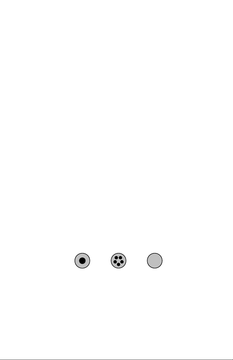
Type of Core: In addition to the ten standard wire diameters, solders also come
in three core types--single core, multi-core, and solid core. Single-core solder
has one hollow cavity at its center filled with flux. Multi-core solder has several
smaller-diameter flux cavities clustered around the center. The manufacturers of
multi-core products claim better flux dispersion, but--in practice--both single and
multi-cores work acceptably well. Solid-core solder has no flux cavity. When
using solid-core solders, you must apply a flux paste to connections by hand
using a brush or syringe.
Size of Core: Not all flux cores are the same size. The core-size of wire solder
is especially important because it controls the amount of flux delivered to each
connection. Core size may be specified as a number (Kester No. 66), a generic
name ("regular"), or a flux percentage (3.3%). Flux percentage is based on the
weight of the flux as compared to the weight of 60/40 alloy. Three
"manufacturer's standard" core sizes are shown below:
5
Page 11
Regular
Medium
Small
3.3%
No. 66
2.2%
No. 56
1.1%
No. 50
For general bench work and field repairs, "regular-core " (3.3%) solder delivers
the most flux, providing the fastest chemical action and best preparation of metal
surfaces. For hand assembly operations where metals are highly solderable and
surfaces pre-cleaned, 2.2% or even 1.1% solder will do the job--and leave less
residue behind for clean-up.
It's always important to check core size when you select a roll of solder. Solder
wires with low flux delivery may perform poorly on unprepared surfaces, and
may also cause your iron to "de-wet". De-wetting (or loss of tinning) is a
condition where solder no longer adheres to the tip because there isn't enough
flux available to keep it free of oxides. If forced use solder with a medium or
small core for general bench work, apply supplemental flux to each connection
before heating. This will protect your iron and to ensure adequate joint
preparation.
LESSON 2
Kinds of Flux
Flux is essential for successful hand-soldering. However, not all fluxes have the
same chemical composition or working characteristics. Different formulations
do the job in slightly different ways. In this section, we'll take a closer look at
what flux does, and cover the various types of flux in common use for hand
soldering.
How Flux Works: When exposed to air, most "raw" solderable metals quickly
attract oxygen molecules and form a layer of oxide. Once oxide forms, the
surface is rendered chemically "passive". This means no molecular bonding
sites are available for combining with other metals! If you apply solder to a
passive oxidized surface, it will bead up into a ball and pull away--much like
water on a freshly waxed automobile (Figure-A). This process is called
retraction. Solder retracts because there are no bonding sites on the surface
where it can take hold and hang on. Instead, a ball forms because internal
cohesion attracts the solder molecules toward each other.
6
Page 12
Metallic oxide
A. Cohesive forces pull solder into a ball. B. Adhesive forces spread solder out.
Solder
Solder
retracts from
surface.
Oxide-free
Solder "wets" surface.
Base Metal
Base Metal
Flux is a specially-formulated chemical agent that removes oxide to expose the
base metal underneath. Once oxide is removed, the surface becomes chemically
"active" (Figure-B). This means the molecular bonding sites are restored and the
surface is again free to combine with other metals. When liquidous solder is
applied to an activated surface, powerful molecular forces take over--pulling the
solder downward and forcing it outward to cover the area in a process called
adhesion. When solder adheres to a chemically active surface, we say it wets the
surface. Complete wetting is essential for good solder connections.
In addition to removing oxides, flux has a second job--to form a protective
coating over the newly-activated metal. Although flux is a semi-solid at room
temperature, it melts and spreads well below the melting temperature of solder.
This allows it to flow ahead of liquidous solder--activating the surface and
locking out air to prevent re-contamination.
Finally, it's important to remember that flux isn't a "cleaning agent". Flux
removes oxides through chemical action and floats them off the surface in a
chemical suspension. If metal is dirty, greasy, or contaminated in other ways, it
should be cleaned prior to applying flux. Also, note that flux residue contains
the oxides it has removed after the solder connection is made. In some
applications, these deposits may need to be removed through cleaning.
Common Types of Flux
Fluxes fall into two general categories--inorganic and organic. Inorganic, or
"acid-core" types, are normally used for plumbing and are far too corrosive for
electronic applications! Most electronic solder fluxes are organic. Organic flux
falls into three classes: rosin, water-soluble organic, and solvent soluble
organic. Of those groups, rosin flux is most common. Rosin is a natural
substance produced by pine trees that contains abietic (a-bee-tic) acid. Rosin
fluxes are classified by their degree of chemical activity and residue
conductivity. Some rosins are mild and poorly-conductive, while others are very
aggressive and more conductive. The two most-common rosin fluxes are RMA
and RA:
RMA Flux: "Rosin--mildly activated" flux (RMA) is a good choice for
assembling products made from highly solderable metals. The cleaning action of
RMA is adequate for hand assembly in a well-controlled manufacturing
environment, but generally insufficient for general bench and field work where
7
Page 13

oxidation is more prevalent. The residue from RMA flux is relatively nonconductive and non-corrosive.
RA Flux: "Rosin--fully activated" flux (RA) is the most widely-used flux, and
clearly the best choice for bench and field work. RA flux delivers more
aggressive cleaning action, and it activates a wider range of solderable metals
than RMA. Although RA residue is more conductive and corrosive than RMA,
it is also "self-encapsulating". This characteristic isolates corrosive agents from
air and moisture to prevent long-term contamination. On the down side,
encapsulation may interfere with probe contact during testing procedures, and its
protection may fail to hold up when exposed to extreme humidity and moisture.
Other rosin flux formulations are available, but rarely used for hand soldering.
For example, "R" flux (non-activated rosin) is too mild for most practical
applications, and "highly-activated RA" leaves a highly corrosive residue that
must be removed immediately after use. In addition to the popular RMA and
RA rosin fluxes, other formulations such as water-soluble and no-clean flux are
now widely available in wire solders.
No-Clean Flux: "No-clean" flux contains few solids (2-5%), and leaves only a
small trace of non-corrosive and non-conductive residue behind. This, in turn,
eliminates the need for cleaning after the job is completed. No-clean flux is less
aggressive than RA, which reduces its usefulness for general field and bench
work where oxidation my be poorly controlled. However, "no-clean" works very
well for hand-assembling new circuit boards, and is especially popular with
technicians and engineers for surface-mount prototype work.
Water-Soluble Flux: This organic water-soluble flux consists of citric,
glutamic, or lactic acids dissolved in a water or alcohol base. On the plus side,
water-soluble flux is more aggressive that rosin fluxes, and it successfully
activates some metals that RA flux cannot. On the negative side, water-soluble
fluxes leave organic acids and salts behind which are potentially corrosive and
conductive--and these must be removed immediately after use. Of course,
removal is relatively easy, since only water and mild non-toxic cleaning agents
are needed to do the job.
Supplemental Flux
When hand soldering, flux is delivered primarily through the core of solder wire.
In some cases, "core flux" may not provide sufficient chemical action to get the
job done, and additional flux is needed to fully prepare the area. Supplemental
fluxes are available from distributors in most popular types (RMA, RA, noclean, etc.), and may be dispensed as a paste or liquid--depending upon
packaging.
8
Page 14
Flux Jar
Flux Syringe Flux Pen
Flux Pastes are most often packaged in a small jars or a plastic syringes. Jar
paste is applied to larger areas with a flux brush, and to miniature surfaces and
with a wooden toothpick. Patse-filled syringes come with special applicator tips
which offer controlled flow-rate and pin-point placement. Replacement tips are
available in a variety of sizes. Syringes provide convenient packaging, and they
work well for a wide range of tasks. The flux pen delivers flux as a liquid, much
like a felt-tip marker delivers ink. Pens are especially convenient for miniature
PC board and surface-mount work. Supplemental pastes and liquids may
evaporate and dry out when exposed to air for long periods. Be sure to cap or
cover all flux containers when not in use. Refrigerating during prolonged
periods of non-use helps extend shelf life.
PC Board Cleaners and Flux Removal Solvents
Most off-the-shelf cleaners are formulated for removing rosin-core flux residues
(RMA and RA). Although cleaning is routine during automated PC board
assembly, residue removal may not be required for general purpose bench and
field hand-soldering jobs. That's because RMA and RA fluxes are selfencapsulating, and "no-clean" fluxes leave no harmful residue behind.
If cleaning is needed to satisfy a cosmetic or technical requirement, consider
using an alternative to older-style CFC-based organic solvents. While CFCs are
very effective, the price, toxicity, and environmental impact may not be
justified. Less-toxic organic solvents, alkaline saponifiers (sap-on-a-fires), and
emulsion cleaners are now available to do the job with minimal risk. Organic
solvents dissolve rosin deposits, while saponifiers and emulsion cleaners convert
them into water-washable substances.
Before using any flux removal product, read instructions carefully! Most
organic solvents require adequate ventilation and other safety precautions for
safe use. A stiff-bristle brush is usually needed to remove particles and debris (a
discarded toothbrush works well for this). After handling cleaning chemicals, be
sure to clean hands thoroughly before eating or smoking. Finally, never
improvise by using solvents not specified for flux removal. These may expose
you to a needless health hazard, and may also damage chemical-sensitive plastics
on the PC board!
9
Page 15

Purchasing and Using Solder--A Quick Review
By now, you're probably getting the idea that "grabbing any old roll of solder" to
do a job might not yield the best results! Before you select a product, ask
yourself the following questions:
1. Is the solder alloy right for the job?
2. Is the wire size matched to the task (too small, to big)?
3. Is the core type acceptable (single, multi, or solid?)
4. Is the core size going to deliver the right amount of flux?
5. Is the type of flux right for the application?
6. Is supplemental flux needed?
7. Will the flux residue require removal?
8. If so, what type of cleaning product is best?
You probably won't always be able to find exactly what you want! However, if
you understand solder specification and what they mean, substitution should be
easy. For example, for most routine PC board hand-soldering jobs, a 60/40 alloy
in a .031" or .040" wire size with a 3.3% (regular) RA flux core works well.
From that starting point, you can add other solders to accommodate specific
tasks. For example, a 63/37 alloy in a .020" wire size with 3.3% RA (or "noclean") flux works well for surface-mount applications. And, a roll of "fat"
60/40 might come in handy for assembling high-power equipment with large
components.
When forced to use "SE" (or someone else's) solder, always read the label first!
If the flux is unaggressive or the core size "small", use supplemental flux
(usually RA). If the flux is highly-activated RA or water-soluble, remove the
residue afterward. Finally, if it's acid core or the roll's unmarked, put it back and
find something else. It always pays to be an informed consumer!
10
Page 16

LESSON 3
Soldering--Health and Safety
Industrial hygienists evaluate occupational safety in terms of acute and chronic
health hazards. Acute hazards relate to immediate threats from traumatic injury.
A misplaced cable that causes someone to trip and fall downstairs is an acute
health hazard. Chronic hazards relate to long-term threats from toxic agents. A
chemical known to cause cancer after prolonged exposure to its fumes is a
chronic health hazard. Soldering isn't regarded as a high-risk activity in either
category, but there are hazards you need to know about and avoid.
Acute Hazards
Burns: The most obvious short-term health hazard associated with solder is
heat. Iron tips typically operate at 600-800 degrees F, and the temperature of
molten solder exceeds 350 degrees F. Moreover, liquidous solder can spatter
over a wide area without warning. Either of these heat sources can inflict painful
burns and even permanent injury.
To reduce your vulnerability to heat-related injuries, always wear appropriate
clothing and eye protection (no shorts or tanks tops if you value your skin). In
the event of accidental skin contact with a hot iron or hot solder, immediately
run cold water over the burn area. This first-aid response cools skin rapidly to
limit tissue damage, and anesthetizes damaged nerve endings to reduce pain!
Never apply butter or any other substance--only ice or a cool wet towel. If
severe blistering or wounding breaks the skin barrier, seek further medical
attention as soon as possible to prevent secondary infection. Also, have any eye
injury resulting from a solder spatter checked at once--no matter how minor.
Electric Shock: Electrocution is a second acute hazard associated with
soldering and solder irons. Most thermostatically-controlled solder stations
supply low voltage to soldering tools, greatly reducing the risk of injury.
However, solder-station control units, self-contained desoldering tools, and unregulated bench irons usually connect directly to the 110-volt AC line. Inspect
plugs and power cords frequently for heat damage, iron burns, or wear. Also,
confirm the integrity of power-plug grounds. Damaged power cords should
always be replaced, and never repaired using electrical tape or shrink tubing!
Finally, never attempt soldering operations on a piece of electronic equipment
while it is connected to a power source!
11
Page 17

Chronic Hazards
Lead Poisoning: Lead is a toxic substance that accumulates in the body over
time. If toxic levels are reached, the impact on health will be serious. Medical
outcomes may include damage to productive organs, cancer, birth defects, colic,
kidney disease, paralysis, brain damage, and even death! Fortunately, electronic
soldering is done at temperatures well below the "fuming point" of lead, so lead
vapors pose little threat to your health. Mishandling lead-bearing solder wire
presents a greater long-term hazard. Each time you use solder wire, a small
quantity of lead is transferred to your fingers. This, in turn, may be ingested
when you handle food or smoke cigarettes. Although the amount of lead
transferred may be small, it can accumulate to dangerous levels over time. To
prevent unwanted lead from accumulating in your system, it's extremely
important to wash your hands thoroughly after handling solder--especially before
eating or smoking!
Flux Fume Inhalation: Solder fluxes may also present a chronic health hazard.
Some flux vapors contain mineral acids that are irritating to the skin and toxic to
inhale. Repeated exposure may produce asthma-like repertory symptoms or
chronic throat irritation. To minimize your exposure to flux vapors, ventilate the
area around your soldering station. A small portable air-filter, or a larger ducted
ventilation system, work well for removing airborne irritants. If ventilation is
unavailable, avoid breathing in visible plumes of smoke or strong-smelling
vapors. Even a small fan aimed across your work area will help to blow irritants
clear and reduce exposure.
Other Workplace Hazards: In addition to solder, electronic work areas
usually harbor a collection of flux solvents, degreasing chemicals, and PC board
etching chemicals. Also, high-speed drilling and abrasive cleaning of PC boards
generates airborne particles of epoxy and copper dust. Most of these substances
present one or more health hazard, ranging from mild respiratory irritation to
severe or deadly toxic effects. Be sure to obtain and read MSDS information
(hazardous material data sheets) for all chemicals stored in your work area.
Know how to use them properly, and know what to do in case of an accidental
spill or over-exposure!
12
Page 18
LESSON 4
Soldering Irons
Types of Irons: There are a lot of different soldering irons out there, and
choosing the right one can be as confusing as choosing the right roll of solder!
Electronic distributors offer products ranging from ten-dollar hobby irons to
microprocessor-driven rework stations costing several thousand dollars. All
soldering irons do pretty much the same thing--heat connections and melt solder
alloys. But, there are differences in how they do the job--and how well they do
it! Here's a survey of the popular hand-soldering irons in use today.
Low-Cost Hobby Iron: These are simple low-cost consumer products intended
for home-owners and beginning-hobbyists. Most provide a two-wire power cord
connected directly to a fixed-output 110-volt 30-40 Watt heating element. Iron
tips are ungrounded and unsuited for working with static-sensitive components.
Elements and tips aren't designed for continuous use, and replacement parts may
be hard to find--making these products "throw-aways" when they fail (not
suitable for lab or shop use).
Handle
Power Cord
Barrel
Tip
Heating Element
Unregulated 110-volt Professional Iron: These irons work on the same
principle as low-cost hobby irons, but the heating elements and tips are higher
quality and designed for continuous use. Power cords may be two-wire (isolated
tip) or three wire (grounded tip). Tips and elements are easily replaced, and a
variety of wattages and tip styles may be used with the same basic handle
assembly. Some "high-end" 110-volt irons may have thermostatic temperature
control, but most will not.
Shield
Cord
Main Body
Cartridge Socket
Grip
Removable Heat Cartridge
Replaceable Tip
13
Page 19
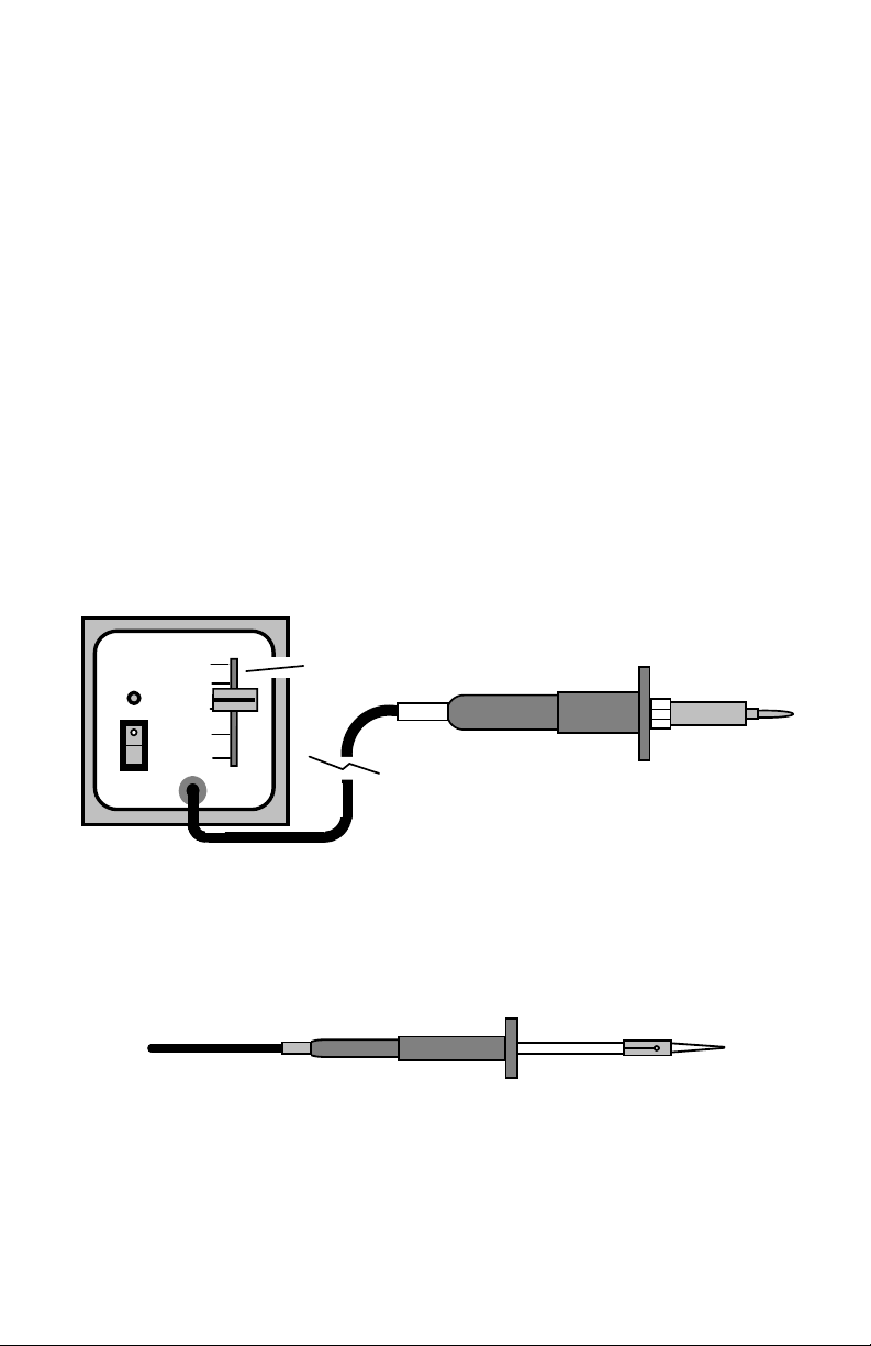
Transformer Powered Soldering Station: Transformer-powered soldering
irons run on low voltage. Typically, a transformer unit enclosed in a separate
bench-top control box converts 110-volts to 24 volts. Irons plug into a socket on
the front panel of the box, allowing for rapid substitutions. Virtually all
transformer-powered stations use three-wire AC cords and provide grounded
iron tips. Grounded tips bleed off electro-static discharge (ESD) that might
otherwise build up on the iron and damage sensitive electronic parts during
construction.
Two kinds of temperature control are popular, depending on the solder station's
model and manufacturer. One method uses magnetic-thermostat switching with
a temperature-sensitive element built into the iron's tip. The type of tip you
install controls temperature. The classic "Weller Soldering Station", an industry
mainstay for over 30 years, uses the magnetic thermostat design.
Other soldering stations use an electronic thermostat that provides continuously
adjustable temperature control. All thermostatically-controlled irons apply
element power on demand to maintain a more constant tip temperature. This is
an important feature not found on lower-cost unregulated irons.
Transformer Unit
TEMP
ON
800
700
Thermostat Control
600
PWR
Mini-Irons: With the advent of surface-mount technology and increased
miniaturization, a smaller version of the conventional soldering iron has gained
popularity. Light-weight "mini-irons" (or soldering pencils) outfitted with ultrafine tips reach into tight spots where other irons can't reach. Mini-irons are
available in both unregulated and thermostatically-controlled models.
Min-Iron
Alternative Soldering Irons: For field work or quick bench jobs, many people
prefer to use a "no-plug-in, fast heat" alternative to the traditional iron. The
most common energy sources for these irons include internal rechargeable NiCd
batteries and liquid butane fuel. Portable types may not deliver the power and
14
Page 20
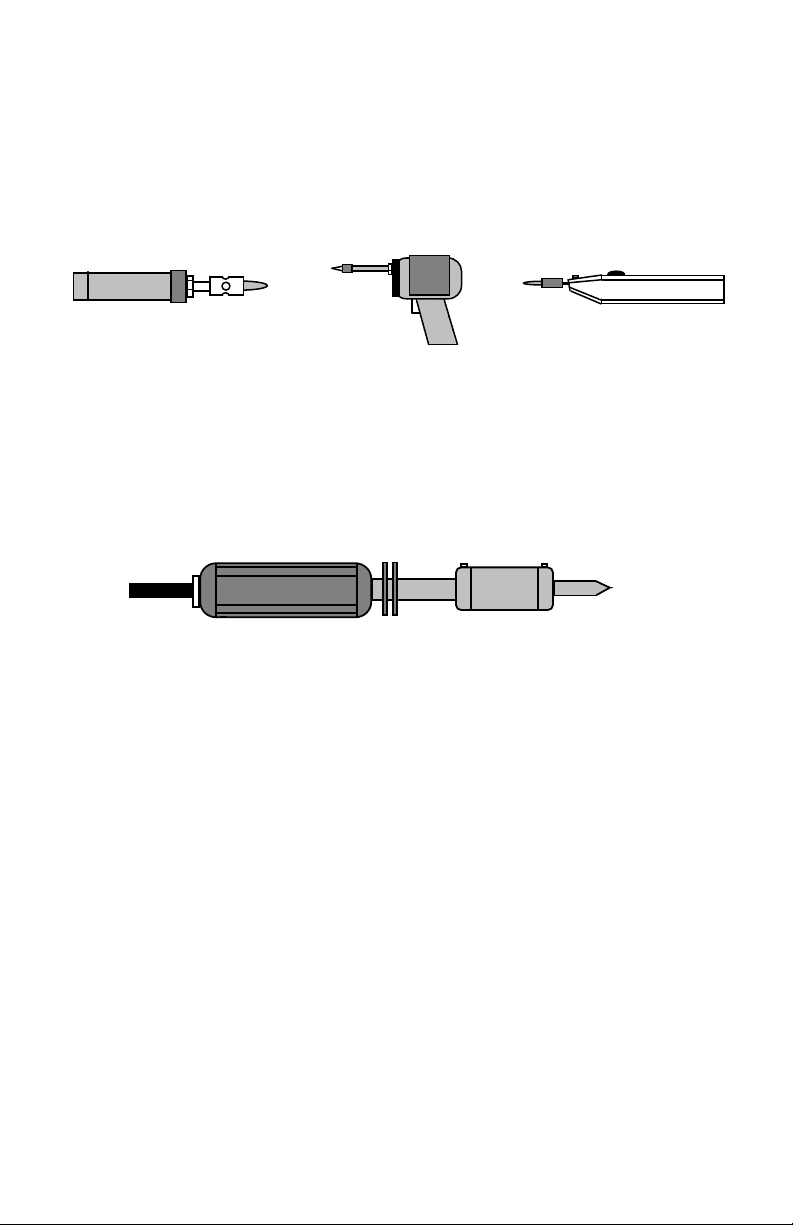
temperature regulation of a transformer powered bench station, but they get
small jobs done quickly without need for running extension cords or removing
equipment from remote locations. Another type of alternative iron, the triggeroperated soldering gun, has been around for many years. These days, batterypowered versions are especially popular.
Butane Iron
Battery-Powered Gun
Battery-Powered Iron
High-Capacity Irons: High-output irons are characterized by powerful heating
elements (100 watts or more), elevated tip temperatures (up to 1000-degrees F),
and massive tips. These "Big-Bertha" irons are especially useful for heating
large surface areas, heavy-gauge wiring, and certain types of RF-cable coaxial
connectors. Most shops and labs have one tucked away for special jobs. Highoutput irons can inflict severe burns very quickly, and must be handled with
plenty of respect!
High-Capacity Iron
Other specialized resistance-soldering systems are sometimes used for connector
installation--especially in manufacturing. Resistance soldering units consist of a
powerful low-voltage high-current transformer connected to a special clamp-on
hand-tool. When the hand-tool is clamped on, it literally turns the entire metallic
part into a heating element! Heating is uniform and fast with these systems.
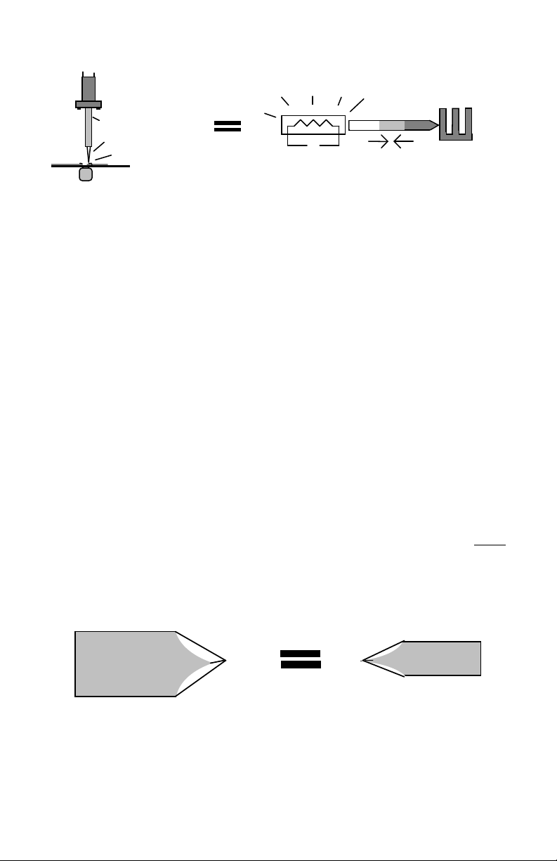
How Soldering Irons Work: A soldering iron has two jobs. First, it generates
thermal energy (or heat) by means of a heating element. Second, it stores up and
transfers that heat to a solder connection via the tip. Prior to contact with a
solderable connection, the iron pre-heats well above the melting temperature of
solder (typically 600-800-degrees F). As it heats, a substantial reservoir of
thermal energy becomes stored in the barrel and tip. Upon contact, an energy
exchange takes place that simultaneously heats up the solder joint and cools
down the iron. Most of the heat required to complete an average connection
comes from stored energy alone. However, the element assists by pumping new
thermal energy into the tip to slow its rate of cooling. Once tip contact is
broken, the element immediately begins to reheat the iron, restoring an energy
reservoir in preparation for the next connection.
15
Page 21
Solderable Metals
in Connection
Cool
Heat Sink
Heat Source
Tip
Solderable Metals
in Connection
Element
Heat Source Heat
Tip
Hot
Exchange
Mass, Temperature, and Thermal Energy: The amount of heat energy stored
by your iron depends on several factors, but the two most important ones are the
tip's mass and the tip's temperature.
Mass: As the iron's element pumps heat energy into the barrel and tip, the
molecules move faster--causing the tip to get hotter. When the iron makes
contact with a cold connection, heat energy is liberated and the molecules start to
slow down. The greater the metallic mass, or the more molecules you have in
your tip, the more thermal energy it will store for every degree of temperature
rise. An iron with a big tip stores more thermal energy for every degree of
temperature rise than a small one. That's because more molecules are available.
Temperature: The higher the tip's temperature rises, the more thermal energy
you can store (per ounce, gram, or whatever). That's because it takes more
energy to make a fixed number of molecules move faster. Conversely, the
further the temperature drops, the more energy you can liberate. Faster-moving
molecules have more energy to give off.
To put this in perspective, say you need to heat a connection to 400 degrees F so
it will melt solder. It makes sense that a 800-degree F tip will contribute more
thermal energy to the heating process than an identical tip heated to only 600degrees F. However, a more massive tip heated to 600-degrees F could
contribute the same amount of energy as the less massive 800-degree F tip-because more storage mass is available in the bigger tip.
600-F
Thermal energy storage depends on
both MASS and TEMPERATURE.
800-F
Without getting into BTUs (British Thermal Units) and the finer points of
hermodynamics, we can generalize the concept and say:
16
Page 22

1. A more massive tip contributes more energy to a solder connection than a
smaller tip (per degree of temperature rise).
2. A hotter tip contributes more energy than a solder connection that a cooler tip
(per unit volume of tip mass).
3. And, finally, a larger and hotter tip contributes a lot more energy
smaller cooler tip.
Of course, practical considerations limit how massive or hot a "real world"
soldering iron can get! Irons need to be relatively small and light-weight to work
on today's miniaturized equipment. Also, any time tip temperatures rise above
750-800 F, excessive heat can easily destroy sensitive miniature components and
damage solder pads on PC boards. It all comes down to finding the right
balance.
Selecting Unregulated Irons: The heating element in an iron without
thermostatic control remains powered continuously. Continuous heating means
the iron cannot adjust itself to a very wide range of heat demands. If the iron is
too small for a given job, the tip will cool too rapidly and won't transfer enough
heat to melt solder. If too large, it may overheat sensitive components and
damage PC boards. Ideally, the wattage of the heating element--along with the
size and shape of the tip--will provide a good "fit" with the demands of the job at
hand. The chart below provides guidance for selecting an unregulated iron:
Element Tip Temp. Tip Dia. Application
25-W 625 1/8" Precision, SMD
30-W 700 1/8" Instrument repair
35-W 750 3/16" Light PC board
50-W 800 1/4" PC-board, small connectors
60-W 750 5/16" Hand-wiring, installing connectors
than a
In addition to choosing the right iron, it's important to choose the right tip.
We've noted that tips with greater mass store more energy (that's why irons with
more powerful heating elements come with larger tips installed). A small
diameter tip with a thinly-tapered end has less mass available for storing energy-and less contact area to transfer heat onto the connection. This could be an
advantage when soldering extremely fine or temperature-sensitive work, but an
extreme disadvantage when soldering heavy parts onto large PC board land
areas. For heavy jobs, a large-diameter tip with a blunt screwdriver shape stores
and delivers energy more efficiently.
Using Thermostatically-Regulated Irons: Thermostatically-regulated irons
and solder stations are more flexible because they can adapt to a wider range of
heat demands than unregulated irons. While unregulated iron elements are
17
Page 23

relatively small and run continuously, regulated element are larger and turn off
as soon as the iron reaches a pre-set tip temperature. This limits the amount of
thermal energy stored in the tip, preventing damage to sensitive components and
circuit board pads. As tip contact is made with the cool surface of a connection,
the thermostat senses a temperature drop and applies full power on the heating
element. The larger element contributes significantly more thermal energy to the
tip than would be available from a smaller unregulated element. As a result, the
regulated iron can solder larger connections and recover more quickly than its
unregulated counterpart.
By the same token, a regulated iron with a continuously-adjustable thermostat
offers even more flexibility than one with a fixed-temperature thermostat.
Adjustable thermostats may be used to establish the quantity of thermal energy
stored in the tip. For extremely fine work, reducing the temperature control
below normal settings reduces the amount of stored thermal energy, protecting
small PC board pads and temperature-sensitive parts from damage. By the same
token, increasing the temperature control above normal increases the amount of
thermal energy stored for big jobs.
TEMP
800
ON
700
600
PWR
A. Temperatures 600-F and below
are best for miniature work--less
likely to damage small parts and
delicate pc-board soldering pads.
ON
PWR
B. Temperatures around 700-F
are best for general pc-board
work--enough energy to solder
quickly without damaging board.
800
700
600
TEMP
TEMP
800
ON
700
600
PWR
C. Highest temperatures are
reserved for larger connections
and large land areas on pc boards.
Use caution to prevent damage.
In the end, unregulated and regulated irons are both capable of doing a good job.
However, the size of the unregulated iron you select--or the way you adjust your
soldering station's heat controls--can make a big difference in how well you
perform as a craftsman!
Here are some signs that will help you recognize when it's time to make a
change:
Too Little Heat: When your iron fails to deliver enough thermal energy, solder
may melt slowly, incompletely, or not at all. If solder is melting at the point of
iron contact, but not beyond, find a more powerful iron or crank up the
thermostat! A properly heated solder connection flows outward--wetting the
entire area.
18
Page 24

Too Much Heat: When the iron is too hot, you may observe more smoke and
an increase in flux spattering. You may also begin to see de-wetting because
flux is burning off rather than coating and protecting the connection area. Worst
of all, the iron may begin delaminating and lifting pads and traces off the PC
board! If this happens, get a lower-power iron or turn down the heat fast--before
irreversible damage destroys the board!
LESSON 5
Soldering Iron Tips
Manufacturers provide a wide range of tips to go with the irons they sell, and
choosing the right tip can be as important as choosing the right iron! Here's a
brief survey of the more popular tips in use today:
Screwdriver Tip: The screwdriver tip provides a wedge-shape that's especially
handy for working on boards and terminals with flat areas. The extra width
provided by the blade improves contact area and promotes rapid heat transfer. A
long shank with a narrow blade stores and delivers less heat, favoring
miniaturized applications. A short shank with a broad tip stores more heat and
delivers it more rapidly for larger components or broad PC land areas. The one
you choose depends on the kind of work you do.
Chisel Tip: This variation on the screwdriver is wedged on one side only-providing a large contact area and fast heat delivery to flat surfaces.
Conical Tip: Shaped like a cone, these tips concentrate heat toward one spot for
"pin-point" soldering. Conical tips work especially well for platethrough type
PC boards, where heat is focused on a small solderable eyelet imbedded in the
PC board. Conical tips also work well for soldering miniature connectors and
terminals. Long and skinny conical tips deliver thermal energy at a slower rate
than short stocky conical tips. Short cones deliver thermal energy faster for
heating large component leads, eyelets, and heavy terminal areas.
Short
Broad
Screwdriver
Medium
Narrow
Long
Chisel
Short Medium
Conical
Long
19
Page 25

with copper core
Some manufacturers offer special variations such as the "bent conical tip" or
"micropoint tip" for special applications. Also, for slightly better heat transfer,
some narrow screwdriver tips may be used interchangeably with the longer
conical tips.
Tip Construction: Most iron tips are made from copper, a metal with unusually
good thermal storage and heat transfer characteristics. Although great for
storing heat, copper is quite soft and oxidizes rapidly when exposed to air. If
used "as is", copper tips erode quickly and require continual maintenance. To
prevent this, manufacturers electroplate them with one or more protective layers
to add toughness and extend life.
One popular tip-plating scheme is illustrated in the following diagram. The
outer layer of the shank is electroplated with chrome, a non-solderable metal.
Chrome is applied to prevent solder from wetting and sticking to the back
portion of the tip. This reduces the need for cleaning, and prevents the shank
from becoming stuck in the iron barrel due to a buildup of solder deposits. A
layer of nickel plating beneath the chrome outer-surface prevents corrosion and
"pitting" as the tip ages. The inner-most layer of electroplate is iron, and this
covers the entire tip. Iron helps harden the shank, and it prevents solder from
combining directly with the softer copper core beneath the tip's contact area.
Note that the contact area is tinned with solder. Maintaining this surface is an
important part of tip maintenance and care. Without complete wetting of the
contact area, heat transfer would be extremely difficult--and the iron would fail
to perform!
Nickel electroplating
prevents corrosion
The exact composition and layering of a tip's outer shell may vary from
manufacturer to manufacturer, but most high-quality tips have multiple layers of
electroplating to ensure long life and top performance.
20
Chrome electroplating prevents wetting
Copper Core
Working part of tip
dipped in 63/37 solder
Iron barrier prevents
solder from combining
Page 26

LESSON 6
Tip and Iron Maintenance
Soldering irons are subjected to the natural forces of oxidation, corrosion, and
metal fatigue--but at a greatly accelerated rate due to high operating
temperatures! To fight the forces of deterioration, irons require frequent
inspections and maintenance. Inspections are needed because irons rarely "quit
cold" when the get tired. Most often, performance will deteriorate slowly.
Those "perfect connections" that used to seem routine will become progressively
more difficult to make! When this happens, you could be experiencing a "bad
bench day". However, it's far more likely your soldering iron and tip are
overdue for some serious TLC!
Caring for Tips: If you keep your tips clean and well-tinned, they'll take good
care of you. Here are some suggestions for getting the best performance:
1. Always use a cleaning sponge. A thoroughly dampened cleaning sponge is
the best way to clean your tip prior to making connections. Heat-resistant
iron or pencil stands with built-in sponge trays are inexpensive--and they're a
"must" for every bench! If the water in your area has a high mineral content,
use distilled water--otherwise, water-born minerals may bond with the iron
electroplating in the tip and contaminate it. Also, don't neglect your NiCd or
butane-powered irons--these tips should be clean, too!
2. Always clean your tip before making the connection--never after! Tip
cleanings remove old contaminated solder so it won't mix in with the "new
stuff" you're about to apply. However, once a tip is sponge-cleaned, only a
very thin layer of solder remains. If you don't reinforce this thin coating
quickly--either by making a connection or by re-tinning the iron--it will
oxidize and may cause your tip to de-wet! To prevent de-wetting, always
leave your iron with a healthy protective coating of fresh solder between
connections--and coat it especially well before shutting down. Never spongeclean and shut down.
3. Some solders are tougher on tips than others. When using small-diameter
or low-flux solders, check the condition of your tip frequently. These solders
often fail to deliver sufficient flux to maintain good tinning! To prevent dewetting, apply supplemental flux and keep the tip well coated with solder
between connections. Also, be aware that highly-activated rosin and organic
water-soluble fluxes are more corrosive than less aggressive types, and
regular use may mean more frequent tip replacements. This is a normal
condition, so don't avoid using aggressive fluxes to save your tips! Just keep
a closer eye on their condition.
21
Page 27

4. Never use the tip as a prying tool. Screwdriver tips shouldn't be used to
pry up flattened-over leads or to wedge apart solderable surfaces. This will
damage the electroplated iron shell protecting the tip's contact surface and
expose the copper core. Exposure, in turn, will cause rapid tip erosion. Also,
avoid applying excessive iron pressure to PC boards to improve thermal
contact. This, too, will damage electroplating--and it may delaminate the
pad!
5. High-temperatures are tough on tips. When using tip temperatures above
650-700 degrees F, take time to clean and re-tin your iron more often.
Oxidation occurs more rapidly at higher temperatures, increasing the
possibility of de-wetting.
6. Never file, sand, scrape, or grind a plated tip to clean it. Once
electroplating is compromised, core erosion will destroy the tip rapidly! If
the tip is contaminated enough to require dressing, use a special polishing bar
(available from many electronic supply houses). If the tip's outer plating is
cracked or delaminated, don't waste time dressing it out. Replace it
immediately.
7. Renew dewetted tips. If a tip de-wets and resists further tinning, you still
may be able to save it. While the tip is hot, try a gentle cleaning with a soft
wire brush or a very fine-grit emery paper (avoid aggressive abrasives that
could break through the electroplate). Once the heavier oxides are removed,
dip it in RA flux and attempt re-tinning. It may take several flux-cleaning
and tinning cycles to restore full wetting. If this fails, replace the tip!
22
Page 28

Soldering Iron Cleaning and Maintenance
Like tips, irons get "crusty" and need maintenance. These steps will help you
restore performance, improve safety, and extend life!
1. Remove heavy oxides and corrosion. High temperatures cause the rapid
buildup of scale and oxide deposits. These, in turn, decrease heat efficiency
by increasing surface area. Use a soft wire brush to remove as much oxide as
you can. However, avoid aggressive abrasives that could destroy metal
plating.
2. Tighten screws and fittings. Constant heating and cooling causes metallic
parts to expand and contract. Over time, hardware loosens, decreasing
contact and lowering thermal efficiency. Gently tighten loose screws and
fittings, being careful not to over-torque (tap holes may strip easily after
prolonged exposure to heat and corrosion).
3. Wipe down sponge trays. Lead is toxic, and sponge trays tend to collect a
lot of it over time! Remove the iron sponge and wipe down the tray area
thoroughly. Dispose of lead debris carefully, and replace the cleaning sponge
with a new one. Wash your hands after handing lead-contaminated materials.
4. Inspect cords and electrical connections. Hot soldering irons and PVC
electrical cords don't always mix! Inspect cords closely for heat fatigue,
cracking, tip burns, and other signs of damage. Also, clean low-voltage plugs
on solder stations. If these get corroded, the iron may lose thermal output.
On irons with grounded-tips, connect a DVM between the AC plug's ground
lug and the tip to check continuity. Never attempt to repair cords with tape
or shrink tubing. Buy new ones! Burn-proof replacement cords are now
available for many irons.
5. If a component is going bad, replace it. Over time, heat and corrosion
eventually win out, and iron parts need replacement! Order new parts at the
first indication of trouble--before the iron's impaired performance
deteriorates the quality of your work. Many items such as thermostat sensors,
barrel assemblies, elements, and cords are available from electronic
distributors or directly from manufacturers. Also, keep in mind that irons
don't live forever. If yours needs a lot of new parts and its overall condition
is deteriorating, it may be time to purchase a new one!
So far, we've covered a lot of material about solders, irons, tips, and supplies-but we haven't said too much about the hands-on art of soldering. The remainder
of the course is devoted to that topic!
23
Page 29

LESSON 7
Soldering Applications
Most hand soldering involves constructing circuit boards and wiring them into
larger pieces of equipment. In this section, we'll cover the basic techniques used
for constructing boards. We'll also cover the soldering methods used for
installing jacks, switches, and connectors.
Circuit Board Evolution and Circuit Board Types
Circuit board technology has changed a lot over the years. Here's a "thumb-nail"
look at their evolution--along with a rundown of the kinds of boards you're likely
to encounter:
Single-Sided PC Boards: When printed circuit boards first came on the scene,
all wiring was etched onto a copper-coated side, and all components were
mounted on the opposite non-metalized side. The copper side was called the
solder-side because all solder connections were made on that surface. The
opposite side was called the component-side. The board itself was called a
single-sided PC board because only surface was metalized.
Double-Sided PC Boards: Over time, as miniaturization increased and RF
(radio frequency) construction techniques improved, designers began using
copper on both sides of the board for wire-traces and grounds. These became
known as a two-sided or double-sided boards. Although wiring was etched on
both sides, construction methods usually dictated that components be mounted
on one side only. Thus, the "component-side" and "solder-side" terminology
stuck--and is still used today. When traces needed to be "through-connected"
from one side to the other, this was done by soldering component leads on both
sides of the board, and also by installing short wires through the board called
vias.
Plate-Through PC Board: Eventually, techniques evolved for metal-plating
the inside surfaces of the holes drilled in the boards. These metallized holes
were called plate-throughs. Plate-throughs made electrical contact between pads
on each side of the board. This innovation eliminated the need for soldering
components on both sides and also eliminated the need for installing vias by
hand. That, in turn, made automated soldering of two-sided boards both costeffective and practical. A PC board with two etched surfaces and plate-through
holes is called a double-sided plate-through board.
24
Page 30

Component Side
Through-Hole Mounting
Solder Side
Single-Sided Double-Sided
Double-Sided Plate-Through
Multi-Layer Boards: With the advent of miniaturized computers and massive
LSICs (large-scale integrated circuits), PC boards have now taken another step
forward. Some PC boards contain multiple layers of conductive traces laminated
into the board which are interconnected by plate-throughs. These are called
multi-layer plate-through boards.
Through-Hole and SMD Layouts: Increasingly, sub-miniature leadless
components are secured directly to the board's surface--reducing the need for
drilled mounting holes. Because of this, we now distinguish between through-
hole construction, where leads or mounting tabs penetrate the board, and SMD
or surface-mount construction, where parts are held in place with adhesives and
secured to pads with solder. This course focuses on through-hole construction,
but many circuit boards now combine a hybrid mixture of both. Often, throughhole components are mounted on the top surface and SMD components mounted
on the bottom. In other cases, they are mixed together.
104
Surface-Mounting
Single-sided, double-sided, and multi-layered PC board construction are all
currently popular--depending on the application. Unplated and plated holes are
also widely used. However, there are important differences between platethrough and non-plate-through hand-soldering techniques. In the next section,
we'll look at the soldering methods for each.
Circuit Board Soldering Techniques
Soldering Single-Sided Boards: Single-sided boards remain popular for lab
projects and low-cost electronic products because they are simpler and cheaper
to make (many hobbyists and circuit designers make their own). When
constructed properly, single-sided boards are extremely reliable and resistant to
environmental deterioration.
Cleaning and Preparing: Etched surfaces on commercially-manufactured
boards are usually pre-tinned to reduce oxidation. However, surfaces on
25
Page 31

experimental or home-made boards may be untreated copper. Clean copper is a
highly solderable metal, but it oxidizes and corrodes rapidly when exposed to
air--losing solderability. As a result, raw copper surfaces must always be
cleaned thoroughly immediately prior to construction. Steel wool, bronze wool,
and chlorinated abrasive household cleaners work well for stripping away
corrosion and heavy oxides. After cleaning, surfaces should appear bright,
shiny, and free of oxide spots and streaks. If untinned boards will be constructed
over a period of time after cleaning, store them in a dry air-tight container to
minimize recontamination.
If surfaces are pre-tinned, don't scrub them with abrasives. This will remove
rather than clean the protective coating! A quick washing with soap and water-or degreasing in a mild solvent--should do the trick.
Component Installation: Single-sided circuit boards normally provide
somewhat larger pads than plate-through boards because the pad surface is the
primary retention area for the solder connection. When installing components in
unplated holes, the lead should be bent over and pressed firmly against the pad
surface. The greater the contact area between lead and pad, the more
mechanically and electrically secure the connection. Note that--whenever
possible--leads should be bent in the same direction as incoming tracks to
prevent inadvertent contact with adjacent pads or tracks (see below).
Good
Not Good
Applying Heat: Place the iron tip so it contacts both the component lead and
pad. The objective is to heat both metal surfaces simultaneously. After about 1
second, apply solder to the opposite side of the wire from the iron tip (see
below). The solder should melt due to contact with the solderable surfaces, and
not from contact with the iron itself. Never melt solder on a connection by
touching it to the iron tip!
Solder
Solder shouldn't make
direct contact with
iron tip.
Tip
Iron
26
Page 32

Solder should melt, flow, and wet the surface of the lead and pad to form a
bright smooth connection. Rocking the iron slightly as solder flows will promote
better solder distribution around the connection.
Double-Sided Board, No Plate-Throughs: Most commercially manufactured
double-sided PC boards now have plate-through holes. However, hobby or
prototype boards may not! On two-sided boards, the major grounded-plane
surface is usually on the component side (top), and most of the interconnecting
tracks are on the solder side (bottom). To ensure good RF (radio frequency)
grounding, it's important to keep all ground connections on top as short as
possible (see below). If ceramic disc capacitors are used, carefully remove any
"flash" around the grounded lead prior to installation to exposure a solderable
surface. Make sure all vias are installed and soldered on both ends.
Bypass
Capacitor
Flash Removed
Solder
Relief in groundplane
Groundplane
Solder
Double-Sided (or Multilayered) Plate-Through Boards: The solder
technique for plate-through boards is different because the wall of the platethrough hole (or eyelet) provides the contact surface for the component lead.
When installing parts in plate-throughs, it isn't necessary to bent leads tight
against the pad surface. Only bend enough to ensure the component remains
secured in place during soldering.
Bend to hold component
in place.
Plate-Through Eyelet
27
Page 33

The objective is to solder the lead to the inside of the hole. Heat the lead and
plate-through eyelet for about 1 second. Then, apply solder to the surface-allowing it to melt and wick down around the lead. Avoid loading up the pad
with solder--the important thing is to fill the gap around the lead. Nip off any
excess lead when the connection is complete.
Allow solder to wick
down into hole
Apply solder
to opposite side
of lead.
around lead.
Use a similar soldering technique when installing components in multilayer
boards. Note that plate-through vias do not require soldering because electrical
contact is already established between layers by the plate-through itself.
Hand Wiring Techniques
Before the days of PC boards, virtually all electronic interconnections were
made using wire. Today, designers try to include everything--jacks, switches,
connectors, and indicator lamps--on the printed circuit board. The reasoning is
simple! It's a lot cheaper and faster to install "user-interface" components on a
PC board with automated soldering than it is to hand-wire these parts onto a
control panel using wire! Despite this, we haven't entirely escaped the need for
hand wiring. When interconnections are made using wire, it's called point-to-
point wiring. Point-to-point wiring is still widely used to interconnect circuit
boards, power and signal leads, and electromechanical devices that can't be
included on PC boards.
Cable Terminations: Interconnecting cables take two forms. Some may be
soldered directly to pads provided on the circuit board. Others may be soldered
to connectors that plug into the circuit board. Either way, interconnecting cables
must be prepared carefully because they'll be subject to flexing and movement.
Stranded wire is commonly used because it is more flexible than solid wire and
it's less likely to break. Harnessing wires together with plastic ties helps to
immobilize them, reducing stress. Good soldering technique reduces the chances
of breakage or short-circuiting on the circuit board (see following diagram).
28
Page 34

Sleeve
exposed
shields
Dress
insulation
close
Avoid
"wicking"
Wrap wire
around
terminal
Use minimal
solder
Plug
To prevent exposing un-insulated wire, install sleeving on ground shields. Also,
dress wire insulation close to the board surface. When installing wires, avoid
applying excess heat and solder--this causes hot solder to wick up wire strands,
melt the insulation, and destroy wire flexibility (a major cause of breakage). The
same rules apply to plugs. Dress insulation close to terminal tabs, and use
minimal heat to prevent wicking. Follow the plug manufacturer's assembly
instructions for capping plugs and immobilizing wires.
Larger control-system harnesses may use crimp-lugs to interconnect wires on
terminal blocks. If these wires carry high-frequency signals, or if the terminals
are exposed to harsh environmental conditions, crimping and soldering may be
specified. When installing the lugs, crimp the wire (or wires) in place first--then
apply heat, allowing solder to wick back into crimp area. Avoid depositing
solder on the screw-down portion of the lug. This will make tightening to the
block impossible later on!
Iron Tip
Keep solder clear of
terminal contact area.
Wick solder
into crimp area
Solder
Chassis Connectors: When soldering wires to chassis connectors, observe the
same precautions you would for PC board installation. If the connector terminal
allows the wire end to pass through an opening, wrap it tight for a good
mechanical connection before applying solder. If the wire end inserts into a
hollow connector terminal, tin it prior to insertion for easier installation and
better solder coverage.
29
Page 35

Sleeve exposed connector terminals
Heat hollow terminal pin
Apply solder to opening
Wrap wire for mechanical hold
Chassis BNC connector
Sleeve
Chassis DIN connector
Make sure all wire strands are dressed cleanly. A stray strand hanging off a
connector lug or terminal could cause a short circuit later on.
Soldering--Good and Bad
If a connection is bad there will be tell-tale signs. By the same token, if a
connection is technically "perfect", there will be tell-tale signs of that, too! Here
are some visual clues for recognizing each:
Solderability vs Retraction: Solder adheres when surface areas are activated
and bonding sites are available. If preparation is "good", the entire solderable
area is available for bonding, allowing solder to flow outward and adhere
uniformly. If preparation is "bad", surfaces resist bonding and the connection
shows evidence of retraction. Here, solder may appear to "roll down" to a
visible margin on metal surfaces, and "potholes" may be present where solder
failed to adhere.
Pad Contamination--
uneven coverage,
pits, retraction.
Wire okay
Wire Contamination--
uneven margin, retraction.
Pad okay
The cure for retraction is usually better PC board cleaning or lead preparation.
If component lead contamination is a problem, heavy oxides can be removed
easily by scraping with a hobby knife or swiping with emery cloth. A pencil
eraser will clean pads without removing tinning.
How Much Solder is Enough
In a good connection, solder appears bright, shiny, and uniformly distributed.
Also, the surface of the connection may appear slightly concave due to strong
forces of adhesion pulling solder outward during wetting. Avoid using excess
solder. If the connection looks like a "solder mound" instead of a "solder
volcano", you've applied too much!
30
Page 36

Not Enough
Just Right
Too Much
Common PC Board Problems: The three most frequent problems occurring
with soldered connections are:
Cold Solder Joints: The "cold solder joint" is a catch-all term for connections
that fail to make a reliable electrical contact. This could be due to one of the
following:
1. A "grainy" or fractured joint formed because it was disturbed during the
plastic phase of cooling.
2. One solderable surface on the connection was heated insufficiently, and
bonding failed.
3. Retraction due to oxidation caused the joint to fail due to insufficient contact
area.
Cold solder joints can often be repaired by re-heating and re-activating the joint
surfaces with the introduction of more flux and some fresh solder.
Solder Bridges: These short circuits are usually the result of "gapping" between
two adjacent pads or tracks (60/40 solder is more likely to gap than 63/37).
Usually, removing some of the solder with wick or a solder vac will eliminate the
problem.
Lifted Pads: A pad lifts when its bonding to the PC board fails due to excessive
heat. A lifted pad, by itself, may not cause an immediate malfunction. However,
sooner or later, a track break usually occurs at the junction of the lifted pad and
the still-secured pc track. The fastest repair technique is to install a new part,
and then solder the unclipped lead to a point further down the incoming track.
Cold-Solder Joint
Solder Bridge
Lifted Pad
Looking for trouble (or excellence) in a solder connection is a little like going on
an archeological expedition! The story is virtually always there, recorded for the
ages in the solder itself. All you need do is look closely and read the signs!
31
Page 37

Electrolytic
LESSON 8
Component Handling and Preparation
We've looked closely at what happens on the bottom side of the board. This
section takes a look at what happens on top. In order to follow diagrams and
build working circuits, you'll need to recognize common components and read
their value codes.
Resistors
Resistors limit current flow and provide voltage drop in electrical circuits. For
low power circuitry, 1/4 or 1/8-watt molded resistors are most common. The
resistive value of these devices is displayed by means of a banded color code.
Resistor Color Code
1st Digit
2nd Digit
Multiplier
Tolerence
(gold or silver)
Black = 0 (tens)
Brown = 1 (hundreds)
Red = 2 (K)
Orange = 3 (10K)
Yellow = 4 (100K)
Green = 5 (1Meg)
Blue = 6
Violet = 7
Gray = 8
White = 9
Silver = 10%
Gold = 5%
When you look at a resistor, check its multiplier code first. Any resistor with a
black multiplier band falls between 10 and 99 ohms in value. Brown designates
a value between 100 and 999 ohms. Red indicates a value from 1000 to 9999
ohms, which is also expressed as 1.0K to 9.9K. An orange multiplier band
designates 10K to 99K, etc.
Capacitors
Capacitors store electric energy, block the flow of DC current, and permit the
flow of AC current. Unlike modern-day resistors, capacitors no longer use a
color code for value identification. Instead, the value, or a 3-number code, is
printed on the body.
Value Code
10 pF = 100
100 pF = 101
1000 pF = 102
.001 uF = 102*
.01 uF = 103
.1 uF = 104
Multilayer
(270 pF)
271
Ceramic Discs
(.001 uF) (.1 uF)
102
104
-
1 uF
1uF
|
35V
|
+
32
Page 38

Multilayer caps are similar to a surface-mount "chip" capacitors, except that
leads are spot-welded onto each end of the capacitor body. Multilayers have
superior operating characteristics, but the lead welds may fail if the device is
over-stressed. For this reason, never use force to seat a multilayer cap into the
PC board. If the spacing isn't right, pre-form the leads to the correct spacing
before installation!
Incorrect
Ooops!
Correct
For ceramic disc and multilayer capacitors, the transition from pF (pico-Farads)
to uF (micro-Farads) occurs at 1000 pF (or .001 uF)*. The first two digits
indicate a numerical value, while the last digit indicates a multiplier (same as
resistors).
Electrolytic capacitors are always marked in uF. Electrolytic are polarized
devices and must be oriented correctly during installation. If you become
confused by markings on the case, remember the uncut negative lead is always
slightly shorter than the positive lead.
Chokes and Inductors
Chokes block the flow of AC current while permitting the passage of DC.
Molded chokes commonly used today are color-coded in much the same way as
resistors (see below). While some chokes are specified in nano-Henries (nH) or
milli-Henries (mH), most used in communications work are specified in microHenries (uH). The choke's third color band specifies its range. For example, a
red, red, silver choke is .22 uH, a red, red, gold choke is 2.2 uH, a red, red, black
code is 22 uH, and red, red, brown means 220 uH. The fourth color band
indicates tolerance10% for silver and 5% for gold.
Molded Choke Color Code
1st Digit
2nd Digit
Multiplier
Tolerence
(gold or silver)
Black = 0 (tens uH)
Brown = 1 (hundreds uH)
Red = 2 (mH)
Orange = 3
Yellow = 4
Green = 5
Blue = 6
Violet = 7
Gray = 8
White = 9
Silver = .10 uH or 10%
Gold = 1.0 uH or 5%
33
Page 39

Slug-Tuned RF Coil
Air-wound coils, toroids, and RF inductors belong to the same family of
components, but offer no standard method of color-coding or identification.
Check building instructions or part numbers for more specific identification.
Air-Wound Coil Toroid Coil
Diodes
Diodes allow current to flow in one direction, but not in the other. Like
electrolytic capacitors, diodes are polarized devices that must be installed
correctly. Always look for the banded--or cathode--end when installing, and
follow instructions carefully.
Cathode
(shorter Lead)
Transistors
Transistors are solid-state devices capable of amplifying or switching. If
transistors are installed incorrectly, damage may result when power is applied.
Transistors in metal cases have a small tab near the emitter lead to identify
correct positioning. Semiconductors housed in small plastic cases (TO-92) have
an easily-identified flat side to identify mounting orientation. Many specialized
diodes and low-current voltage regulators also use this type packaging. Larger
plastic transistors and voltage regulators use a case backed with a prominent
metal tab to dissipate heat (T-220). Here, orientation is indicated by the
positioning of the cooling tab.
34
Diode
Metal Can Device Plastic Device Tab-cooled Device
Emitter
Flat Side
LED
Metal Tab
Page 40

Before soldering a transistor in place, be sure to check specific installation
instructions or consult a technical data sheets for that device.
Integrated Circuits
Integrated circuits, or ICs, contain many active and passive devices (transistors,
diodes, capacitors, resistors, etc.) which are connected together to perform a
specialized task. These devices have a minimum of eight leads. Proper IC
positioning is indicated by a dot or square marking located on one end of the
device. A corresponding mark will be silk-screened on the PC board and printed
on the kit's parts-placement diagram. To identify specific IC pin numbers for
testing purposes, see the diagram below. Pin numbers always start at the keyed
end of the case and progress counter-clock around the device, as shown:
8 7 6 5
Installation
Key
1 2 3 4
Pin Numbers
Installation
Key
35
Page 41

or Pliers
LESSON 9
Desoldering for Repair or Replacement
In addition to installing parts, it's helpful to know how to get them out! If you
work carefully and use the right techniques, parts may be substituted or replaced
with little or no damage to PC boards. Here are some common methods for
removing them:
Heat and Pull: This old standby method involves heating a connection on the
solder side of the board, and tugging the component free on the opposite side.
Because components are removed in "see-saw" fashion, this technique is usually
limited to parts with two leads. There's a fairly high risk of component damage
from lead stress, so use care when extracting parts you intend to recycle.
Heat and Brush: The "heat and brush" method is another older technique that
works best on single-sided boards where the pad surface is used for lead
retention. First, the connection is heated--then molten solder is swept off the pad
using a small stainless-steel wire brush. After sweeping, the bent-over
component lead can usually be pried up with a hobby knife and removed. "Heat
and brush" can get messy, since molten solder may fly onto nearby tracks and
pads. Always inspect the surrounding area for solder bridges and debris! Other
more contemporary methods may work better.
Solder Wick: Solder wick is a very handy soldering aid made from fine-mesh
copper braid. It is highly-solderable, and will tend to "draw up" molten solder
when applied to a heated connection. Wick is available in various widths from
electronic distributors, and some types are pre-fluxed to enhance performance.
To use wick, place it on the soldered surface and press down gently with a hot
iron. As solder melts beneath, it will flow into the copper mesh--up and away
from the contact surface on the pad. Wick is effective on flat surfaces and platethrough eyelets alike! If a plate-through lacks sufficient surface solder to start
the wicking process, add a little more to the connection to "prime the pump".
After each application, nip off the solder-saturated end of the wick and start
over. Wick is a preferred method for desoldering both through-hole and SMD
boards.
Heat and Pull
Hemostat
36
Heat and Brush
Solder Wick
Page 42

Vacuum Solder Suckers: This popular method of solder removal involves
heating a connection, and then using vacuum to suck the molten solder up into a
container. Solder suckers come in many different types, and cost anywhere from
a few dollars to several thousand. The simplest types are rubber squeeze balls
with heat-resistant nozzles and spring-loaded hand pumps with trigger releases.
Both types are inexpensive, work marginally well, and rely on heat from a
conventional iron to melt solder.
Squeeze-Bulb Sucker
Spring-Loaded Vacuum Pump
Professional "rework stations" represent a giant step forward in terms of
sophistication and performance. A few solder-gun-style hand-held units are
available, but most are larger bench-top machines intended for high-volume
repair and manufacturing applications. Some develop suction using built-in
electric vacuum pumps, while others rely on compressed air lines to drive
pneumatic pumps.
Hand-Held Unit
Bench-Top Unit
All suckers, from the simple to the complex, require frequent cleaning and
maintenance to prevent clogging and ensure acceptable vacuum levels. Most
work well on all types of boards, although you usually get what you pay for in
terms of overall performance and usefulness. When used properly, suckers may
represent the fastest and least invasive way to remove sensitive components.
Other Tools of the Trade
Removing components from boards and clearing solder from plate-through holes
sometimes requires more than a desoldering tool alone can deliver. Stubborn
leads may break off or get stuck, solder spatters have a way of wedging
themselves into tight areas, and solder may not come out of plated holes with any
37
Page 43

of the normal solder-removal methods. Many of these bench nightmares can be
resolved with the help of a few simple tools.
Electronic Shears: Electronic shears, or "nippy cutters", are sharp close-cutting
pliers that have virtually replaced traditional diagonal pliers for snipping off
lead-ends. A good pair of these can slip under partially soldered-down leads and
lift them off a soldered surface without damaging the pad.
Hemostats: Originally an emergency room medical tool, these small clamping
devices are probably the best "third hand" you'll ever own for handling miniature
components. They've become so popular in the electronics industry, companies
now market them exclusively for printed circuit board work.
Dental Tools: Here's another medical tool that's found its way onto nearly
everyone's electronics bench. The two most useful types are the "dental
explorer", a small curved semi-flexible pick used for checking out cavities--and
the "dental scaler", a sharp and tough little tool used for removing dental scale.
Most electronic supply houses now have "dental tool" assortments sold
exclusively for electronics work.
Small Hobby Drill: A small electric hobby drill is especially useful for
removing left-over solder from plate-through holes. It will also drive a small
burr to remove solder bridges, cut through tracks, or strip off tough insulating
laminates from PC boards. Most hobby shops and larger electronic distributors
carry an assortment of drill bodies, chucks, miniature bits, and rechargeable
batteries. Be sure to order one with an adjustable chuck rather than a fixed-size
collet. When cleaning out plate-throughs, the bit you select must be smaller than
the hole size, or the plate-through wall will be destroyed.
Hobby Knife: The classic ExactoTM Knife outfitted with a #11 straight blade
rounds out the list of "most popular bench tools" for PC board and hand-wiring.
For cutting, scraping, de-burring, stripping, and scratching--this tool is hard to
beat.
Speaking of tools, this concludes the "book learning" portion of the Vectronics
soldering course. Now, it's time to step up to the plate and do some hands-on
soldering using the Lab portion of the course. Remember to look closely at the
connections you make. More than anything else, the solder will tell you how
well you're doing!
38
Page 44

VECTRONICS SOLDERING COURSE QUIZZES
These quizzes are designed to reinforce the material you've read in each lesson.
Use them as a study aid. If you have difficulty answering two or more quiz
questions, we recommend returning to the lesson for a second pass.
Lesson 1 Solder Alloys and Wire
1. Solder provides a (strong/flexible) ___________ mechanical joint and a
(low/high) __________ resistance electrical path.
2. The three "states" of solder are _____________, _____________, and
__________.
3. Which solder alloy is more able to "wet" metals and bridge short gaps? (A.)
60/40, (B.) 40/60, (C.) 63/37, (D.) 2% silver. [ ]
4. Which solder alloy is most recommended for miniature electronics?
(A.) 60/40, (B.) 40/60, (C.) 63/37, (D.) 2% silver. [ ]
5. Solder with a narrow plastic temperature range is called ____________
solder.
6. Which solder has the narrower plastic temperature range? (A.) 60/40, (B.)
40/60, (C.) 63/37, (D.) 2% silver. [ ]
7. Which type of solder is least toxic? (A.) Low-temp, (B.) 2% silver, (C.)
Lead-free, (D.) 60/40. [ ]
8. When selecting a solder wire gauge, manufacturers recommend using the
(largest/smallest) _____________wire size with the (highest/lowest)
_____________ flux percentage practical to ensure good iron tinning and
adequate flux delivery.
9. For general bench work, which wire-size is a good choice? (A.) .015",
(B.) .031", (C.) .093", (D.) .125". [ ]
10. Which solder core will deliver the most amount of flux? (A.) 3.3%, (B.)
No. 56, (C.) small, (D.) No. 50. [ ]
39
Page 45

Lesson 2 Kinds of Flux
1. Flux prepares solderable metals by removing _______________ from the
surface.
2. When a solderable surface is prepared with flux, it becomes chemically
(active/passive)_______________.
3. When solder pulls away from a surface, it (adheres/retracts)
__________________.
4. When solder "wets" a surface, the process is called (A.) retraction, (B.)
adhesion, (C.) cleaning, (D.) cohesion. [ ]
5. This highly popular flux contains abietic acid, is aggressive, and leaves a
self-encapsulating residue behind. (A.) RMA, (B.) No-clean, (C.) RA,
(D.) Water-soluble. [ ]
6. This aggressive organic flux may contain citric, glutamic, or lactic acid. Its
residue is corrosive and should be removed immediately after soldering.
(A.) RMA, (B.) No-clean, (C.) RA, (D.) Water-soluble. [ ]
7. This moderately aggressive flux contains 2-5% solids, and is especially
useful for hand-soldering "new construction" where parts and circuit boards
are clean.
(A.) RMA, (B.) No-clean, (C.) RA, (D.) Water-soluble. [ ]
8. This organic flux works well for assembly of new products under controlled
conditions, but may not be aggressive enough for general bench work and
repairs. (A.) RMA, (B.) No-clean, (C.) RA, (D.) Water-soluble. [ ]
9. Older-style CFC organic solvents may not make be the best choice for
removing flux residue because they are too (A.) expensive, (B.) toxic,
(C.) harmful to the environment, (D.) all of the above. [ ]
10. (T/F) If you don't have an approved flux remover handy, it's okay to use
Acetone in a pinch. [ ]
40
Page 46

Lesson 3 Soldering Health and Safety
1. A bucket of bricks falling from a 10-story roof is an/a
(acute/chronic)_____________ workplace hazard.
2. Cancer-causing fumes leaking from a chemical tank is an/a (acute/chronic)
_______________ workplace hazard.
3. Accidental skin contact with a hot iron is the most common type of
(acute/chronic) __________________ injury associated with soldering.
4. The best first-aid treatment for a burn to the skin is to apply (A.) cold water,
(B.) ointment, (C.) heavy bandage, (D.) hydrogen peroxide. [ ]
5. Obtain follow-up medical attention for burns that blister or break the skin to
prevent the formation of a bacterial ________________ .
6. A second type of acute injury, called _______________________, might be
caused by a faulty electrical cord on a soldering iron.
7. Exposure to small amounts of lead from handling solder wire over a long
period of time represents a/an (chronic/acute) _________________ health
hazard.
8. When soldering, the best way to avoid ingesting lead is to
________________ your __________________ prior to eating or smoking.
9. Flux fumes may cause asthma-like symptoms and chronic throat irritation.
To reduce exposure, (A.) install a ventilation system, (B.) install a
portable air cleaner, (C.) blow air from a small fan across the work area,
(D.) any of the above. [ ]
10. The EPA requires that every chemical in your work area should be
accompanied by a data sheet called a ___________ (four letters). This
presents important information you need to know concerning potential
hazards, first aid, and emergency spill response.
41
Page 47

Lesson 4 Soldering Irons
1. Some soldering irons have "grounded tips" and some do not. The purpose
of grounding is to prevent (A.) electrocution, (B.) fire, (C.) ESD, (D.)
cold solder joints. [ ]
2. A soldering iron with a heating element that runs "full time" is called a
(regulated/unregulated)____________________________ iron.
3. The transformer in a solder station (boosts/lowers)________________
operating voltage to the soldering iron.
4. The temperature of a solder station equipped with a magnetic-thermostat
switch is controlled by the type of _______________ you install.
5. The amount of thermal energy stored by your iron depends (primarily) on
the tip's _____________________ and ________________________.
6. To increase the thermal storage capacity of an iron, you could:
(A.) increase tip temperature, (B.) increase tip mass, (C.) increase tip
temperature and mass, (D.) all of the above. [ ]
7. To decrease the thermal storage capacity of an unregulated iron, you could:
(A.) install a larger tip, (B.) install a smaller heating element, (C.) install
a fatter tip, (D.) turn up the voltage. [ ]
8. To increase the thermal storage capacity of a continuously adjustable
soldering station, you could turn the temperature control (up/down)
_________________.
9. If solder melts at the point of tip contact, but not over the entire surface area
of the connection, this may indicate your iron has too
(much/little)____________ thermal storage capacity.
10. If pads begin de-laminating and lifting off the pc board when you apply
heat, your iron tip might be too: (A.) cool, (B.) fat, (C.) hot, (D.) sharp
on the edges. [ ]
42
Page 48

Lesson 5 Soldering Iron Tips
1. The three most popular types of tip are the chisel, ___________-
__________, and ________________________.
2. Most tip cores are made from __________________, a soft highly-
conductive metal with excellent heat-storage and transfer characteristics.
3. The entire core is usually protected by an electroplated layer of
_______________.
4. If electroplate layers are worn or scraped away to expose the core, it will:
(A.) overheat, (B.) erode quickly, (C.) no longer tin, (D.) smell really
bad. [ ]
5. Why electroplate the back portion of a tip with nickel? (A.) adds ballast,
(B.) prevents wetting, (C.) provides insulation, (D.) prevents corrosion. [
]
6. Why electroplate a portion of the outer surface with chrome? (A.) adds
ballast, (B.) prevents wetting, (C.) provides insulation, (D.) prevents
corrosion. [ ]
7. If you want to solder temperature-sensitive sub-miniature components, it's
best to use a (short/long)______________ tip with a
(wide/narrow)_________________ blade.
8. If you want to solder a fat lead to a large land-area on a pc board, it's best to
use a (short/long)______________ tip with a
(wide/narrow)_________________ blade.
9. For a slower rate of energy transfer, use a (long/short)______________ and
(skinny/wide)___________________ tip.
10. For a faster rate of energy transfer, use a (long/short)____________ and
(skinny/wide)_______________ tip.
43
Page 49

Lesson 6 Iron and Tip Maintenance
1. A moistened tip-cleaning sponge should be used (before/after)____-
_________ making a solder connection.
2. Last thing, before turning off your iron, (A.) clean the tip with a wet
sponge. (B.) tin the tip with a thick coating of solder. (C.) dip the tip in
flux paste. (D.) dip the tip in cold water to cool it off. [ ]
3. Tip de-tinning may result from: (A.) using small-diameter solder, (B.)
using low-flux solder, (C.) operating the iron at higher-than-normal
temperatures, (D.) all of the above. [ ]
4. The best way to prevent de-tinning is to use _______________________
flux.
5. (T/F) It's okay to use the soldering iron tip to pry solderable surfaces apart.
[ ]
6. (T/F) If a tip de-tins and resists further wetting, attempt a thorough cleaning
and re-tinning procedure before discarding. [ ]
7. Wiping down sponge trays and changing sponges removes what kind of
contamination? ________________
8. It's good to tighten the hardware on your iron, but if you torque screws too
hard, the threads may ____________.
9. (T/F) If you find burned insulation on your iron's electrical cord, it's okay to
repair it with electrical tape or shrink tubing. [ ]
10. Soldering irons run at high operating temperatures, and this accelerates the
process of ______________________ .
44
Page 50

Lesson 7 Soldering Applications
1. For each PC board term (A-G), match a definition by number (1-7):
A. single-sided 1. several PC board layers sandwiched together
B. double-sided 2. conductive pathway between sides of a PC board
C. multi-layered 3. metalized component hole through PC board
D. plate-through 4. leadless surface-mounting component
E. via 5. any component hole through PC board
F. through-hole 6. PC board with two metalized surfaces
G. SMD 7. PC board with one metalized surface
A.____ B.____ C.____ D.____ E.____ F.____ G.____
2. "Raw" copper circuit board patterns are highly solderable, but must be
cleaned immediately before construction because of rapid
___________________ .
3. (T/F) The best way to melt solder onto a connection is to lightly touch the
tip of the iron with the solder wire. [ ]
4. When soldering to pc-board pads that aren't plated through, the primary
contact surface is the________________________.
5. When soldering to PC board pads that are plated through, the primary
contact area is the _______________________________.
6. Connections made using wire are called ____________ -to-
_____________ wiring.
7. When soldering wires onto a pc board: (A.) dress each lead so insulation is
close to the surface of the board. (B.) don't overheat and allow solder to
wick up the wires. (C.) install sleeving over exposed shields. (D.) all of the
above. [ ]
8. If a connection is poor, you'll probably see signs of ___________________,
a condition where the solderable surface resistings bonding with solder.
9. (T/F) The more solder you can deposit on the pad, the better the
connection--especially when working with plate-throughs. [ ]
10. A "cold solder joint" may result from: (A.) A joint disturbed in its "plastic"
phase while cooling. (B.) A connection where one surface was poorly
heated. (C.) A connection where solder failed to adhere due to oxidation.
(D.) All of the above. [ ]
45
Page 51

Lesson 8 Component Handling and Preparation
1. When reading the value of a resistor, the first two color bands represent the
first two digits and the third represents the __________________.
2. The fourth color band (reading left to right) indicates the resistor's
________________.
3. If you have a capacitor marked "104", its value will be: (A.) .001uF, (B.)
.01uF (C.) .1 uF, (D.) 1.0 uF. [ ]
4. Electrolytic capacitors are polarized and must be oriented correctly on pc
boards. When determining polarity, the shorter lead is always (+ or -)
_________.
5. (T/F) Molded chokes use the same general color-code scheme as resistors.
[ ]
6. The banded end of a diode indicates the (cathode/anode)
_________________.
7. On an LED, the cathode is the (longer/shorter)__________________ lead.
8. (T/F) Transistors are non-polarized devices that may be installed either
way. [ ]
9. When a transistor is packaged in a metal can, the tab on the side of the case
marks the (emitter/base/collector)________________________.
10. To find pin #1 on an IC (looking from the top down), first locate the
installation key, then move (clockwise/counter-
clockwise)__________________________ around the device and find the
first pin.
46
Page 52

Lesson 9 Desoldering for Repair and Replacement
1. Which is true for the "heat and pull" method of desoldering components?
(A.) It is least likely to damage the part. (B.) It favors components with
three or more leads. (C.) It is likely to damage the part. (D.) It is the most
highly recommended way to remove parts. [ ]
2. "Heat and Brush" desoldering is apt to spatter molten solder onto
surrounding parts, causing the formation of a _______________
_________________.
3. Solder wick performs better when it is pre-treated with
_________________.
4. If there isn't enough solder on the surface of the connection to start the
wicking process, you should
________________________________________.
5. (T/F) Solder wick is one of the least recommended ways to desolder and
remove components. [ ]
6. Solder suckers use ________________________ to remove molten solder
and deposit it into a container.
7. (T/F) All solder suckers require frequent cleaning and maintenance to
prevent clogging and to ensure efficient operation. [ ]
8. When all normal solder-removal techniques fail, the best way to remove
solder from a stubborn plate-through hole is with a small
______________________.
9. This medical emergency-room and "OR" implement is also one of the most
popular bench tools for clamping and holding small parts or wires. (A.)
retractor, (B.) scalpel, (C.) explorer, (D.) hemostat. [ ]
10. This dental tool is great for removing stubborn bits of solder debris or for
breaking up solder bridges. (A.) explorer, (B.) scaler, (C.) Novocain,
(D.) molar extractor. [ ]
47
Page 53

Answers to quizzes
Lesson 1
(1.) strong, low (2.) solid, plastic, liquid or liquidous (3.) A (4.) C (5.)
eutectic (6.) C (7.) D (8.) largest, highest (9.) B (10.) A
Lesson 2
(1.) oxides (2.) active (3.) retracts (4.) B (5.) C (6.) D (7.) B (8.) A (9.)
D (10.) F
Lesson 3
(1.) acute (2.) chronic (3.) acute (4.) A (5.) infection (6.) electrocution or
electric shock (7.) chronic (8.) wash, hands (9.) D (10.) MSDS or Material
Safety Data Sheet
Lesson 4
(1.) C (2.) unregulated (3.) lowers (4.) tip (5.) mass, temperature (6.) D
(7.) B (8.) up (9.) little (10.) C
Lesson 5
(1.) screwdriver, conical (2.) copper (3.) iron (4.) B (5.) D (6.) B (7.)
long, narrow (8.) short, wide (9.) long, skinny (10.) short, wide
Lesson 6
(1.) before (2.) B (3.) D (4.) supplemental or extra (5.) F (6.) T (7.) lead
(8.) strip (9.) F (10.) corrosion or oxidation.
Lesson 7
(1.) A7, B6, C1, D3, E2, F5, G4 (2.) oxidation or corrosion (3.) False (4.)
pad or pad surface (5.) hole wall, inside of hole (6.) point-to-point (7.) D
(8.) retraction (9.) False (10.) D
Lesson 8
(1.) multiplier (2.) tolerance (3.) .1 uF (4.) - or minus (5.) True (6.)
cathode (7.) shorter (8.) False!! (9.) emitter (10.) counter-clockwise
Lesson 9
(1.) C (2.) solder bridge (3.) flux (4.) add more (5.) False (6.) vacuum or
suction (7.) True (8.) drill (9.) D (10.) B
48
Page 54

VECTRONICS SOLDER COURSE LAB
Parts List
Your kit should contain all of the parts listed below. Please go through the parts
bag to identify and inventory each item on the checklist before you start
building. If any parts are missing or damaged, refer to the warranty section of
this manual for replacement instructions. If you can't positively identify an
unfamiliar item in the bag on the basis of the information given, set it aside until
all other items are checked off. You may then be able to identify it by process of
elimination. Finally, your kit will go together more smoothly if parts are
organized by type and arranged by value ahead of time. Use this inventory as an
opportunity to sort and arrange parts so you can identify and find them quickly.
Qty Part Description Designation
1 75K-ohm ¼-watt resistor
(violet-green-orange)
11 10K-ohm ¼-watt resistor
(brown-black-orange-gold)
10 1K-ohm ¼-watt resistor
(brown-black-red-gold)
1 1-uF electrolytic capacitor C1
3 .1-uF monolithic capacitor C2,C3,C4
10 2N3904 NPN transistor Q1,Q2,Q3,Q4,Q5,Q6,Q7,Q8,Q9,Q10
1 555 8-pin IC U1
1 4017 16-pin IC U2
10 Red LEDs CR0,CR1,CR2,CR3,CR4,CR5,CR6,
1 1N4148 Silicon diode D1
1 9-volt battery clip
1 8-pin IC socket for U1
1 16-pin IC socket for U2
1 DPDT push-action switch SW1
5 4” nylon wire tie
1 30” length of insulated wire
1 VEC-1500K PC board
R2
R4,R5,R6,R7,R8,R9,R10,R11,R12,R13
R1,R14,R15,R16,R17,R18,R19,R20,
R21,R22,R23
CR7,CR8,CR9
49
Page 55

Parts Placement Diagram
Step-By-Step Assembly Instructions
First, a few notes and comments to help you along. Part designators for
components such as R1, C3, etc., appear in the parts placement diagram. The
parts are inserted on the top side of the board; traces are on the bottom side of
the board.
Install the monolithic (multilayer) capacitors so their values are easy to read
once all the parts are installed. Likewise, orient all fixed-resistor color bands in
similar directions. Doing so makes troubleshooting and verifying that no errors
were made during assembly easy.
In these instructions, when you see the term install, this means to locate, identify,
and insert the part into its mounting holes on the PC board. This includes prebending or straightening leads as needed so force is not required to seat the part.
Once a component is mounted, bend each lead over to hold it in place. Use
sharp side-cutters to clip off excess lead length before soldering. Make sure
trimmed leads don't touch other pads and tracks, or a short circuit may result:
Good
50
Not Good
Page 56

The term solder means to solder the part's leads in place, and to inspect both (or
all) solder connections for flaws or solder bridges. Nip off excess protruding
leads with a sharp pair of side cutters.
Generally, it's easier to install small close-to-the-board parts first, and then
mount larger stand-up parts second. Delicate parts usually go on the PC board
last. Concentrate on your soldering while doing the assembly. Don’t attempt to
rush towards completion of the board--that only defeats the purpose of this
course.
Placing components: To help you determine the proper location for each part
the manual contains a pictorial diagram showing the location of each part on the
PC board. Once again, the parts are inserted on the top side of the board; traces
are on the bottom side of the board.
Assembly will begin with installing the ¼-watt fixed resistors. Because these are
all 5-percent tolerance, ending with a fourth gold color band, you need only read
the first three bands of the color code during the following steps. All resistor
leads should be formed as shown below:
.4"
Note: Resistors are non-polarized devices. This means they may be
installed in any direction on the board. When assembling your
board, try to keep all resistor beginning and ending color bands
oriented in the same directions. This makes troubleshooting
easier, and also produces a neater looking board.
Locate a 1K-ohm (1000 ohm) resistor (brown-black-red). Form the
resistor leads as shown above, and install the resistor at location R1.
Use the parts placement diagram for assistance.
The body of the resistor should be resting flat against the PC board surface.
Gently bend the leads to hold the resistor package in place (see the example
below). Using a pair of fine cutting pliers, trim off the excess lead length.
Leads are bent over to provide a good mechanical connection before soldering.
51
Page 57

Based on the work to be done, select a soldering iron with the proper tip and
operating temperature, and also the correct solder to make the connection.
Carefully solder both leads of resistor R1 to the PC board.
Once the soldering operation is completed, carefully examine your work. Is the
connection bright and shiny? Has the solder flowed over the resistor lead and
the PC board surface (wetting) properly? Has solder splashed onto adjacent runs
(if so, it must be removed)?
If the joint is poorly soldered, or is grainy in appearance, reheat the work and use
solder braid or a solder sucker to remove the solder. Try resoldering the
connections again. If the connections are still poor, review your material dealing
with soldering techniques.
When you are satisfied with the soldered connections for the leads
of R1, use a pair of fine cutting pliers to trim the remaining lead
lengths even with the solder connection.
Locate the 75K-ohm (75,000 ohm) resistor (violet-green-orange).
Install at location R2 on the PC board. Following the steps used for
R1, solder and trim the leads for resistor R2.
Locate the ten 10K-ohm resistors (brown-black-orange). These resistors will be
installed at locations R4 through R13 on the PC board. Carefully review each
solder connection as it is made. Do not proceed with soldering until the previous
solder connection is properly made, and any mistakes are corrected. Trim excess
lead lengths after completing each soldering operation.
Install a 10K-ohm resistor (brown-black-orange) at location R4.
Solder.
Install a 10K-ohm resistor (brown-black-orange) at location R5.
Solder.
Install a 10K-ohm resistor (brown-black-orange) at location R6.
Solder.
Install a 10K-ohm resistor (brown-black-orange) at location R7.
Solder.
Install a 10K-ohm resistor (brown-black-orange) at location R8.
Solder.
Install a 10K-ohm resistor (brown-black-orange) at location R9.
Solder.
52
Page 58

Install a 10K-ohm resistor (brown-black-orange) at location R10.
Solder.
Install a 10K-ohm resistor (brown-black-orange) at location R11.
Solder.
Install a 10K-ohm resistor (brown-black-orange) at location R12.
Solder.
Install a 10K-ohm resistor (brown-black-orange) at location R13.
Solder.
Carefully review your work. Make sure that locations R4 through R13 each
contain a 10K-ohm resistor. Examine all of the solder connections. Look for
unwanted solder bridges or poorly made solder connections.
Select ten 1K-ohm (1000 ohm) resistors (brown-black-red). These resistors will
be installed at locations R14 through R23 on the PC board.
Note: save a few of the clipped resistor leads for later use as jumper
wires.
Install a 1K-ohm resistor (brown-black-red) at location R14. Solder.
Install a 1K-ohm resistor (brown-black-red) at location R15. Solder.
Install a 1K-ohm resistor (brown-black-red) at location R16. Solder.
Install a 1K-ohm resistor (brown-black-red) at location R17. Solder.
Install a 1K-ohm resistor (brown-black-red) at location R18. Solder.
Install a 1K-ohm resistor (brown-black-red) at location R19. Solder.
Install a 1K-ohm resistor (brown-black-red) at location R20. Solder.
Install a 1K-ohm resistor (brown-black-red) at location R21. Solder.
Install a 1K-ohm resistor (brown-black-red) at location R22. Solder.
Install a 1K-ohm resistor (brown-black-red) at location R23. Solder.
Select two of the discarded resistor lead clippings. Form both leads
to make jumper wires having a .3" span.
span
discarded lead end
53
Page 59

|
|
1uF
35V
+
-
Electrolytic
Incorrect
Oops!
Correct
Install a .3” jumper wire at location JMP1 on the PC board. Solder.
Install the other .3” jumper wire at location JMP2 on the PC board.
Solder.
Locate the 1-uF electrolytic capacitor.
Important Note: Electrolytic capacitors are polarized devices, and must be
inserted with respect to polarity. The style used in this kit has radial leads; both
leads exit from one end of the device body. The capacitor's plus (+) mounting
hole is noted on the parts placement diagram. If the markings on the capacitor
body are unclear, the plus (+) lead is always the longer of the two.
1 uF
Observing polarity, install the 1-uF electrolytic at location C1. Solder.
Locate the three .1-uF monolithic capacitors. These capacitors will be installed
at locations C2 through C4 on the PC board.
Important Note: A monolithic cap is similar to a surface-mount "chip" capacitor,
except that it has a lead spot-welded onto each end of the capacitor body.
Monolithic caps have superior radio-frequency operating characteristics, but the
lead welds may fail if the device is over-stressed during installation or removal.
For this reason, never use force to seat a monolithic cap into the PC board. If
the spacing isn't right, pre-form the leads to the correct spacing before
installation!
54
Install a .1-uF monolithic capacitor at location C2. Solder.
Install a .1-uF monolithic capacitor at location C3. Solder.
Page 60

Cathode
1N4148
Install a .1-uF monolithic capacitor at location C4. Solder.
Locate the 1N4148 silicon diode. Note this is a polarized device. The cathode
band must be installed as indicated by the parts placement diagram.
Form the leads of the 1N4148 to a .4” span. Be careful not to stress
the glass body, it may crack and fail. Install the 1N4148 diode at
location D1 observing polarity. Solder.
Locate the ten 2N3904 plastic transistors. These transistors will be installed at
locations Q1 through Q10 on the PC board.
Important Note: The 2N3904 transistor body has a flat and rounded side. The
device body outline must correspond to the parts placement outline in reference
to the PC board.
2N3904
All the transistors should be mounted with their bodies at the same elevation
above the PC board.
Install a 2N3904 transistor at location Q1. Solder.
Install a 2N3904 transistor at location Q2. Solder.
Install a 2N3904 transistor at location Q3. Solder.
Install a 2N3904 transistor at location Q4. Solder.
Install a 2N3904 transistor at location Q5. Solder.
55
Page 61

Cathode
LED
(shorter Lead)
Install a 2N3904 transistor at location Q6. Solder.
Install a 2N3904 transistor at location Q7. Solder.
Install a 2N3904 transistor at location Q8. Solder.
Install a 2N3904 transistor at location Q9. Solder.
Install a 2N3904 transistor at location Q10. Solder.
Locate the ten red LEDs. Observe that the cathode lead is the shorter of the two
device leads. The cathode lead is also indicated by a small flat area in the
otherwise round base of the device.
The RED LEDs will be installed at locations CR0 through CR9 on the PC board.
Observe cathode lead orientation. All of the LED device bodies should be
mounted at the same elevation above the PC board surface. The leads of the
diodes are “shouldered”, these should set how high the LEDs sit above the PC
board.
Install a red LED at location CR0. Solder.
Install a red LED at location CR1. Solder.
Install a red LED at location CR2. Solder.
Install a red LED at location CR3. Solder.
Install a red LED at location CR4. Solder.
Install a red LED at location CR5. Solder.
Install a red LED at location CR6. Solder.
Install a red LED at location CR7. Solder.
Install a red LED at location CR8. Solder.
Install a red LED at location CR9. Solder.
Locate the eight-pin DIP IC socket. This is a “low-profile” style socket. Note
that the sockets are keyed to indicate pins 1 and 8. The key is either a “U” or
rectangular shaped notch. The parts placement will indicate proper orientation.
56
Page 62

Inspect each socket carefully, and straighten any bent pins before attempting
installation.
Install the eight pin IC socket at location U1 observing orientation.
Solder.
Locate the sixteen-pin low-profile DIP IC socket. Install the 16-pin
socket at location U2 observing orientation. Solder.
Note: It is very easy to bridge adjacent pins on these sockets because of
the very close spacing; be very careful when soldering. If bridges
occur, remove them using a solder sucker or solder braid.
Locate the push-action DPDT (double-pole/double throw) switch.
Install the switch at location SW1 on the PC board. The white
switch shaft should face the edge of the PC board. The body of the
switch should be flush and parallel to the PC board surface. Solder.
Locate the spool of insulated jumper wire. Install the jumpers as directed below:
Note: For the following steps you will need to determine the proper
wire length needed for each jumper. The jumpers will vary from
about 2 inches to 3.5 inches for the longer runs. The wire
jumpers should rest on the PC board, in the area between the red
LEDs CR0 to CR9, and U1, U2 and SW1. Prepare each jumper
by cutting the wire to length. Strip about 1/8” of insulation from
each end in preparation for soldering.
Strip insulation back 1/8-inch from each end.
Install a jumper between points W8 and WI on the PC board. Solder.
Install a jumper between points W4 and WE. Solder.
Install a jumper between points W9 and WJ. Solder.
57
Page 63

+ red
- black
SW1
Install a jumper between points W3 and WD. Solder.
Install a jumper between points W7 and WH. Solder.
Install a jumper between points W6 and WG. Solder.
Install a jumper between points W2 and WC. Solder.
Install a jumper between points W0 and WA, Solder.
Install a jumper between points W1 and WB. Solder.
Install a jumper between points W5 and WF. Solder.
Locate the 9-volt battery snap.
Insert the black lead at the point marked “GND” on the parts
placement diagram. This is near capacitor C4. Solder.
The red wire from the battery snap should go the point marked
“+9V” on the parts placement diagram, this is near diode D1.
Solder.
Use a 4” nylon wire tie to secure the battery leads to the PC board.
The wire tie hole is located near Q10.
Tie wrap
Locate the NE555 timer IC.
Important Note: An IC body has a small notch, or key, molded at one end, to
indicate pin 1. A small dimple-like body-molding is often found adjacent to pin 1.
Some IC packages may include both key indicators.
58
Page 64

1 2 3 4
8 7 6 5
Installation
Key
Key
Pin Numbers
Align the key on the IC body so it corresponds with the key of
Installation
socket U1. Loosely insert the pins of the socket into U1. All 8 pins
should fit freely into the socket openings. If not, straighten the IC
pins until they do. Using firm and steady pressure, fully seat the IC
into the socket.
Locate the 4017 IC.
Note: The 4017 is a CMOS device, and requires ESD handling
precautions.
Align the key on the IC body so it corresponds with the key of
socket U2. Loosely insert the pins of the socket into U2. All 16
pins should fit freely into the socket openings. If not, straighten the
IC pins until they do. Using firm and steady pressure, fully seat the
IC into the socket.
This completes the assembly portion of the Vectronics VEC-1500K kit. Now is
a good time to carefully recheck all of your wiring and soldering. Check that all
of the ICs, LEDs, diodes and electrolytic capacitors have been installed
correctly.
59
Page 65

Operating Instructions
Connect a fresh battery, and turn the power switch on. The LEDs should
immediately begin flashing in sequence.
The “Blinky Light” project was designed especially for this Vectronics soldering
course. Sit back and enjoy the array of blinking lights! You have successfully
completed your project board.
Note: Changing the value of R2 will change the cycle rate of the
flashing LEDs.
In Case of Difficulty
Only high-quality components and proven circuit designs are used in Vectronics
kits. In very rare instances is a defective component the source of a problem.
Ninety-five percent of the kits returned for factory repair are due to soldering
problems or parts in the wrong locations. We advise repeating the assembly
instructions step-by-step, looking for mistakes or soldering problems. Be
especially wary of electrolytic capacitors and semiconductors. Kit builders often
miss obvious mistakes. Sometimes what is needed is a “fresh” set of eyes. You
may want to enlist a friend to go over your work.
Always check the obvious! Is the battery dead? Is the power switch on?
Connect a fresh battery and turn the power switch on (“ON” is indicated by the
switch remaining in the inward position).
Using a voltmeter, nine volts should be present on pins 4 and 8 of U1, and on pin
16 of U2. Use a DC coupled oscilloscope (5-V per division) and check pin 3 of
U1 for a pulse train.
1. All LEDs flashing, but not in proper sequence: Check jumper wiring.
2. Some LEDs not lighting: Check jumper wiring. Check LEDs for proper
orientation on PC board. Driver transistor installed wrong.
3. LEDs dim, erratic operation: Check battery voltage.
60
Page 66

Theory of Operation
IC U1, a 555 timer, along with resistors R1 and R2, and capacitor C3 form a
simple astable multivibrator circuit. The output of U1 on pin 3 is a square wave
pulse train with a repetition rate that is variable from about 100 mS to about 10
mS.
The pulse train drives IC U2, a CMOS 4017 decade decoder IC. Each positive
going transition of the square wave generated by U1 causes the count of the
4017 to advance by one. The active output of U2 is a high signal level. At any
one time, only one of the ten decade outputs will be in a high signal state. A
clock cycle begins when the square wave goes high, advancing the count of the
4017 by one.
Each of the decade outputs drives a 2N3904 switching transistor. When the
decade output of the 4017 goes high, the associated 2N3904 is driven into
conduction. Bias current to the base of the 2N3904 is limited by a 10K resistor.
When the transistor base is forward biased by the decade output, the transistor is
driven into saturation, or full conduction. This provides a return path to ground
for the Light Emitting Diode (LED), through a 1K current limiting resistor, at the
transistor collector.
Specifications
Power Requirements ....................... Nine volt transistor battery at about 15 mA.
Circuit will operate over a 6 to 15 VDC
supply range.
Flash Rate ....................................... About 100mS to 10mS sequence.
61
Page 67

Schematic
62
Page 68

 Loading...