

Page 1

IMPORTANT WARRANTY INFORMATION! PLEASE READ
Return Policy on Kits When Not Purchased Directly From Vectronics: Before continuing
any further with your VEC kit check with your Dealer about their return policy. If your Dealer
allows returns, your kit must be returned before you begin construction.
Return Policy on Kits When Purchased Directly From Vectronics: Your VEC kit may be
returned to the factory in its pre-assembled condition only. The reason for this stipulation is,
once you begin i nsta lli ng a nd sol deri ng pa rt s, you essenti al ly tak e over the rol e of the devic e's
manufacturer . From this point on, neither Vect ronics nor its dea lers can reas onably be held
accountab le for the qua lity or the outcome of your work. Because of this, Vectronics cannot
accept return of any kit-in-progress or completed work as a warranty item for any reason
whatsoever. If you are a new or inexperienced kit b uilder, we urge you to read the manual
carefully a nd determine whether or not you're r eady to tak e on the job. If you wish to c hange
your mind and return your ki t, you may--b ut you must do i t before you begin c ons tr uc ti on, a nd
within ten (10) working days of the time it arrives.
Vectronics Warrants: Your kit contains each item specified in the parts list.
Missing Parts: If you determine, during your pre-construction inventory, that any part is
missing, please contact Vectronics and we'll send the missing item to you free of charge.
However, before you contact Vect ronic s, please look carefully to c onf ir m you haven't misr ea d
the marking on one of the other items provided with the kit. Also, make certain an alternative
part hasn't been substituted for the item you're missing. If a specific part is no longer
available, or if Engineering has determined that an alternative component is more suitable,
Vectronics reserves the right to make substitutions at any time. In most cases, these changes
will be clearly noted in an addendum to the manual.
Defective Parts: Today's electronic parts are physically and electrically resilient, and
defective components a re r a re. However, if you disc over a n it em duri ng your pr e- c onst r uct i on
inventory that's obviously broken or unserviceable, we'll replace it. Just return the part to
Vectronics at the address below accompanied with an explanation. Upon receipt, we'll test it.
If it's defec tive and appear s unused, we'll ship you a new one right away at no charge.
Missing or Defective Parts After You Begin Assembly: Parts and materials lost or
damaged after construction begins are not covered under the terms of this warranty. However,
most parts supplied with VEC kits are relatively inexpensive and Vectronics can replace them
for a reasonable charge. Simply contact the factory with a complete description. We'll
process your order quickly and get you back on trac k.
Factory Repair After You Begin Assembly: Kits-in progress and completed kits are
specifically excluded from coverage by the Vectronics warranty. However, as a service to
customers, tec hnicia ns ar e availa ble t o evaluate a nd repai r malf unctioni ng kits for a minimum
service fee of $18.00 (½ hour rate) plus $7.00 shipping and handling (prices subject to
change). To qualify for repair service, your kit must be fully completed, unmodified, and the
printed circuit board assembled using rosin-core solder. In the event your repair will require
more than an hour to fi x (or $36.00, subject to change), our technicians will contact you in
advance by telephone b efore p erforming t he work. Def ective unit s should b e shipp ed prep aid
to:
Vectronics
1007 HWY 25 South
Starkville, MS 39759
Page 2

When shipping, pack your kit well and include the minimum payment plus shipping and
handling charges ($25.00 total). No work can be performed without pre-payment. Also,
provide a valid UPS return address a nd a day time phone number where you may be reac hed.
Page 3

TABLE OF CONTENTS
Introduction.....................................................................................................2
Tools And Supplies.........................................................................................2
Before You Start Building...............................................................................3
Soldering Tips:.......................................................................................3
Desoldering Tips:...................................................................................3
Work Habits:..........................................................................................4
Sorting and Reading Resistors:...............................................................4
Reading Capacitors:................................................................................5
Diodes: ...................................................................................................5
Transistors:.............................................................................................6
Integrated Circuits:.................................................................................6
Parts List..........................................................................................................7
Parts Placement...............................................................................................7
Step-By-Step Assembly Instructions...............................................................8
Testing and Alignment ....................................................................................13
Generator Method: .................................................................................13
Off-air Method: ......................................................................................14
Operation Instructions.....................................................................................15
Outdoor Preamp Installations:................................................................15
Building a Bias-T:..................................................................................15
Balun Option T1:....................................................................................16
Feeding Balanced Antennas with the Balun:..........................................18
Installing the VEC-1402DK in a Radio(and other considerations) ........18
External Power Sources:......................................................................... 18
In Case Of Difficulty:......................................................................................19
Preamp Stops Amplifying:......................................................................19
Cannot Align or Test Preamp:................................................................19
Voltmeter Checks:..................................................................................19
Theory Of Operation And Specifications........................................................20
Operation:...............................................................................................20
Specifications:........................................................................................20
Schematic........................................................................................................21
Page 4

VEC-1402DK Instruction Manual High Performance 2 Meter Pre-Amp Kit
INTRODUCTION
More than a preamp, the Vectronics VEC-1402DK is an integrated RF system
that attacks three important modern-day reception problems head-on. First, it
boosts signals at the antenna using a premium-grade 1-dB noise-figure
microwave transistor to overcome RF feedline loss. Second, it provides razorsharp bandpass filtering that prevents your receiver from being choked up with
powerful out-of-band signals. Finally, it provides an optional built-in balun to
eliminate unwanted electrical noises and local RFI signals picked up on the outer
surface of your coaxial line. In short, the VEC-1402DK allows your scanner or
VHF receiver to perform it's absolute best--even in the toughest RF environment!
Preamp fits easily into a small project box or PVC pip e for antenna mounting,
and all parts are provided for powering over the feedline. More immune to
overload and static discharges than inexpensive GaAsFETS. Requires 9-14 volts
dc. Size 1-1/2" x 3" x 1".
TOOLS AND SUPPLIES
Construction Area:
area where you can easily organize and handle small parts without losing them.
An inexpensive sheet of white poster board makes an excellent construction
surface, while providing protection for the underlying table or desk. Welldiffused overhead lighting is a plus, and a supplemental high-intensity desk lamp
will prove especially helpful for close-up work. Safety is an important
consideration. Be sure to use a suitable high-temperature stand for your
soldering iron, and keep the work area free of combustible clutter.
Universal Kit-building Tools:
additional items to complete, virtually all construction projects require a work
area outfitted with the following tools and supplies:
!
30 to 60 Watt Soldering Iron
!
High-temperature Iron Holder with Moist Cleaning Sponge
!
Rosin-core Solder (thin wire-size preferred)
!
Needle Nose Pliers or Surgical Hemostats
!
Diagonal Cutters or "Nippy Cutters"
!
Solder Sucker, Vacuum Pump, or Desoldering Braid
!
Bright Desk Lamp
!
Magnifying Glass
Kit construction requires a clean, smooth, and well-lighted
Although your particular kit may require
BEFORE YOU START BUILDING
2
Page 5

VEC-1402DK Instruction Manual High Performance 2 Meter Pre-Amp Kit
Experience shows there are four common mistakes builders make. Avoid these,
and your kit will probably work on the first try! Here's what they are:
1. Installing the Wrong Part:
and a 10K resistor may look almost the same, but they may act very
differently in an electronic circuit! Same for capacitors--a device marked
102 (or .001 uF) may have very different operating characteristics from one
marked 103 (or .01uF).
2. Installing Parts Backwards:
capacitors to make sure the positive (+) lead goes in the (+) hole on the
circuit board. Transistors have a flat side or emitter tab to help you identify
the correct mounting position. ICs have a notch or dot at one end indicating
the correct direction of insertion. Diodes have a banded end indicating
correct polarity. Always double-check--especially before applying power to
the circuit!
3. Faulty Solder Connections:
bridges. Cold solder joints happen when you don't fully heat the connection-or when metallic corrosion and oxide contaminate a component lead or pad.
Solder bridges form when a trail of excess solder shorts pads or tracks
together (see Soldering Tips below).
4. Omitting or Misreading a Part:
Always double-check to make sure you completed each step in an assembly
sequence.
Soldering Tips:
Cleanliness and good heat distribution are the two secrets of professional
soldering. Before you install and solder each part, inspect leads or pins for
oxidation. If the metal surface is dull, sand with fine emery paper until shiny.
Also, clean the oxidation and excess solder from the soldering iron tip to ensure
maximum heat transfer. Allow the tip of your iron to contact both the lead and
pad for about one second (count "one-thousand-one") before feeding solder to
the connection. Surfaces must become hot enough for solder to flow smoothly.
Feed solder to the opposite side of the lead from your iron tip--solder will wick
around the lead toward the tip, wetting all exposed surfaces. Apply solder
sparingly, and do not touch solder directly to the hot iron tip to promote rapid
melting.
It always pays to double-check each step. A 1K
Always check the polarity of electrolytic
Inspect for cold solder joints and solder
This is easier to do than you might think!
Desoldering Tips:
3
Page 6

VEC-1402DK Instruction Manual High Performance 2 Meter Pre-Amp Kit
If you make a mistake and need to remove a part, follow these instructions
carefully! First, grasp the component with a pair of hemostats or needle-nose
pliers. Heat the pad beneath the lead you intend to extract, and pull gently. The
lead should come out. Repeat for the other lead. Solder may fill in behind the
lead as you extract it--especially if you are working on a double-sided board with
plate-through ho les. Should this happen, try heating the p ad again and inserting
a common pin into the hole. Solder won't stick to the pin's chromium plating.
When the pad cools, remove the pin and insert the correct component. For ICs
or multi-pin parts, use desoldering braid to remove excess solder before
attempting to extract the part. Alternatively, a low-cost vacuum-bulb or springloaded solder sucker may be used. Parts damaged or severely overheated during
extraction should be replaced rather than reinstalled.
Work Habits:
Kit construction requires the ability to follow detailed instructions and, in many
cases, to perform new and unfamiliar tasks. To avoid making needless mistakes,
work for short periods when you're fresh and alert. Recreational construction
projects are more informative and more fun when you take your time. Enjoy!
Sorting and Reading Resistors:
The electrical value of resistors is indicated by a color code (shown below). You
don't have to memorize this code to work with resistors, but you do need to
understand how it works:
Resistor Color Code
Black = 0 (tens)
1st Digit
2nd Digit
Multiplier
Tolerence
(gold or silver)
When you look at a resistor, check its multiplier code first. Any resistor with a
black multiplier band falls between 10 and 99 ohms in value. Brown designates
a value between 100 and 999 ohms. Red indicates a value from 1000 to 9999
ohms, which is also expressed as 1.0K to 9.9K. An orange multiplier band
designates 10K to 99K, etc. To sort and inventory resistors, first separate them
into groups by multiplier band (make a pile of 10s, 100s, Ks, 10Ks, etc.). Next,
sort each group by specific value (1K, 2.2K, 4.7K, etc.). This procedure makes
the inventory easier, and also makes locating specific parts more convenient later
4
Brown = 1 (hundreds)
Red = 2 (K)
Orange = 3 (10K)
Yellow = 4 (100K)
Green = 5 (1Meg)
Blue = 6
Violet = 7
Gray = 8
White = 9
Silver = 10%
Gold = 5%
Page 7
VEC-1402DK Instruction Manual High Performance 2 Meter Pre-Amp Kit
on during construction. Some builders find it especially helpful to arrange
resistors in ascending order along a strip of double-sided tape.
Some VEC kits may contain molded chokes which appear, at first glance, similar
to resistors in both shape and band marking. However, a closer look will enable
you to differentiate between the two--chokes are generally larger in diameter and
fatter at the ends than resistors. When doing your inventory, separate out any
chokes and consult the parts list for specific color-code information.
Reading Capacitors:
Unlike resistors, capacitors no longer use a color code for value identification.
Instead, the value, or a 3-number code, is printed on the body.
Value Code
10 pF = 100
100 pF = 101
1000 pF = 102
.001 uF = 102*
.01 uF = 103
.1 uF = 104
As with resistors, it's helpful to sort capacitors by type, and then to arrange them
in ascending order of value. Small-value capacitors are characterized in pF (or
pico-Farads), while larger values are labeled in uF (or micro-Farads). The
transition from pF to uF occurs at 1000 pF (or .001 uF)*. Today, most
monolithic and disc-ceramic capacitors are marked with a three-number code.
The first two digits indicate a numerical value, while the last digit indicates a
multiplier (same as resistors).
Electrolytic capacitors are always marked in uF. Electrolytics are polarized
devices and must be oriented correctly during installation. If you become
confused by markings on the case, remember the uncut negative lead is slightly
shorter than the positive lead.
Diodes:
Diodes are also polarized devices that must be installed correctly. Always look
for the banded or cathode end when installing, and follow instructions carefully.
Multilayer
(270 pF)
271
Ceramic Discs
(.001 uF) (.1 uF)
102
104
Electrolytic
1 uF
1uF
|
35V
|
+
-
Diode
Cathode
(shorter Lead)
LED
5
Page 8
VEC-1402DK Instruction Manual High Performance 2 Meter Pre-Amp Kit
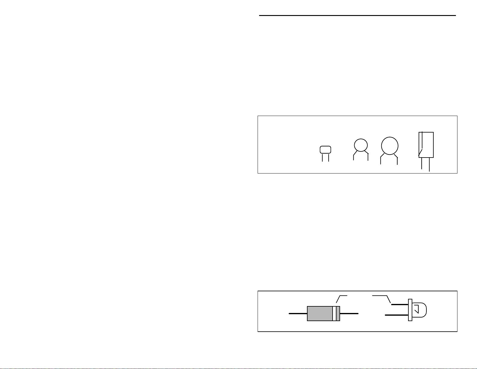
Transistors:
If transistors are installed incorrectly, damage may result when power is applied.
Transistors in metal cases have a small tab near the emitter lead to identify
correct positioning. Semiconductors housed in small plastic cases (TO-92) have
an easily-identified flat side to identify mounting orientation. Many specialized
diodes and low-current voltage regulators also use this type packaging. Larger
plastic transistors and voltage regulators use a case backed with a prominent
metal tab to dissipate heat (T-220). Here orientation is indicated by the
positioning of the cooling tab.
Metal Can Device Plastic Device Tab-cooled Device
Emitter
Flat Side
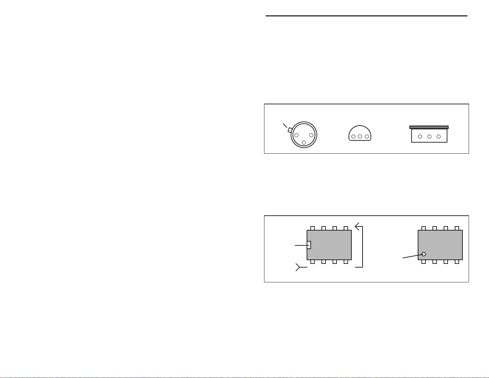
Integrated Circuits:
Proper IC positioning is indicated by a dot or square marking located on one end
of the device. A corresponding mark will be silk-screened on the PC board and
printed on the kit's parts-placement diagram. To identify specific IC pin
numbers for testing purposes, see the diagram below. Pin numbers always start
at the keyed end of the case and progress counter-clockwise around the device,
as shown:
8 7 6 5
Installation
Key
Installation
Key
1 2 3 4
Pin Numbers
Metal Tab
6
Page 9

Page 10
VEC-1402DK Instruction Manual High Performance 2 Meter Pre-Amp Kit
STEP-BY-STEP ASSEMBLY INSTRUCTIONS
Before assembling your kit, please take time to read and understand the VEC kit
warranty printed on t he inside co ver of this manual. Read thro ugh the assembly
instructions to make sure the kit does not exceed your skill level. Once you
begin construction, the kit is non returnable. Finally, if you haven't already
done so, please verify that all parts listed in the inventory are included. If
anything is missing or broken, refer to the warranty instructions for replacing
missing or damaged parts.
Part designators for components such as R1, C3, etc., appear on the silkscreened legend on the component-mounting side of the printed circuit board.
These correspond to the parts placement drawing shown earlier in this manual.
The parts are inserted on the silk-screened side of the board.
Except for Q1, none of the parts used in this preamp are “polarized,” so it makes
no difference which way the parts are inserted into the board. If you insert the
capacitors so the values face the board edges, it will be easier to read the values
when checking for misplaced components during troubleshooting.
If you have any last-minute questions concerning tools or materials needed to
assemble this kit, please refer to the section entitled "Before You Begin." The
directions use two sets of check boxes. Check one when a step is complete and
use the other for double-checking your work before operation. Start kit
assembly by mounting Q1 and the components located on the left end of the PC
board.
! !
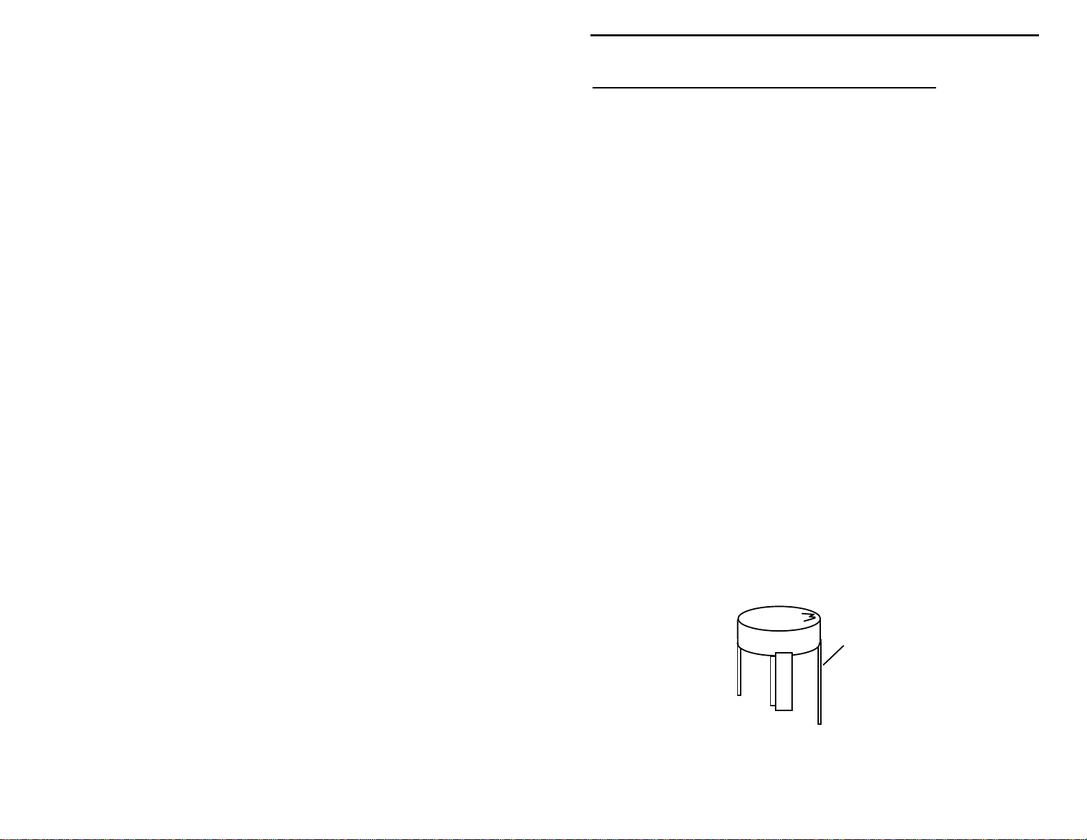
1. Locate transistor Q1, a MRF 901. This device resembles a small black
plastic pill. Note that the longest lead is the collector. The collector is
distinguished by the lette r “M” marking on the de vice body. Carefully
bend each transistor lead down, forming a right-angle to the
component body (the "M" should be on top):
MRF901
Collector
! !
2. Locate the silk-screened footprint for Q1, almost dead-center on the
PC board. Note that the long collector lead is oriented toward
8
Page 11
VEC-1402DK Instruction Manual High Performance 2 Meter Pre-Amp Kit
capacitor C6. Gently insert all four leads into the board, making sure
the collector lead is positioned correctly. The body of Q1 should rest
flush with the PC board surface.
! !
3. Turn the board over, keeping an index finger on Q1 to hold it in place.
Bend each lead over to secure the transistor in place, and trim excess
length off the collector lead. Solder all four leads.
! !
4. Locate part C2, a 22-pF multilayer capacitor. Its body marking is
“22”.
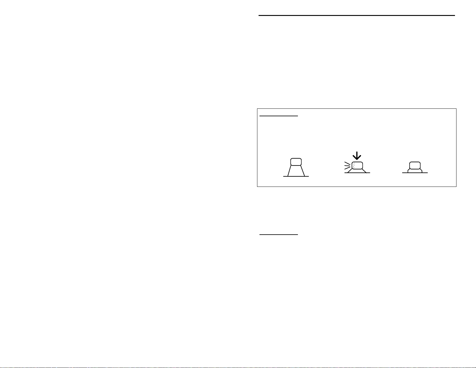
Important Note:
except that it has a lead spot-welded onto each end of the capacitor body.
Multilayers have superior operating characteristics, but the lead welds may fail if
the device is over-stressed. For this reason, never use force to seat a multilayer
cap into the PC board. If the spacing isn't right, pre-form the leads to the
correct spacing before installation!
A multilayer cap is similar to a surface-mount "chip" capacitor,
Incorrect
Ooops!
Correct
! !
5. Insert C2 into its mounting holes, avoiding excess lead length between
the capacitor and the PC board. Solder both leads in place and trim.
Important Note
solder flowed? Is it adhering properly to the foil and leads? Are there unwanted
solder bridges or splashes of solder on the board? Are the leads above the
board as short as possible? From now on, to keep things simple, the instruction
to "solder" indicates soldering both leads, trimming off excess lead ends with
side-cutters, and examining your work for errors.
:
Examine your work. Are the solder joints shiny? Has the
! !
6. Locate part C3, a 1.2-pF ceramic disc capacitor. The body marking is
“1.2”.
! !
7. Insert C3 into the holes shown on the silk-screen outline. Once
again, avoid excess lead length by seating C3 as close to the board as
possible. Solder.
! !
8. The next capacitor is C1, a 56-pF multilayer capacitor. It is marked
with the 3-digit code "560”, or with "56"--its actual value in pF.
9
Page 12

VEC-1402DK Instruction Manual High Performance 2 Meter Pre-Amp Kit
! !
9. Insert C1, ob serving the mounting precaution for multilayer caps, and
solder in place.
! !
10. Locate a 18-pF multilayer capacitor for use at C4. This part has a
"180" 3-digit code, or “18”--the actual value in pF.
! !
11. Install the 18-pF capacitor at C4 and solder.
! !
12. Locate a 4.7-pF disc ceramic capacitor (marked “4.7”) for use at C5.
Install and solder.
At this point, you should have mounted capacitors C1, C2, C3, C4, and C5, and
transistor Q1 on the board with all leads soldered. Make sure each capacitor has
been installed correctly, and check all solder connections.
! !
13. Find two shielded slug-tuned coils (0.074-uH, red coil form). There
are four of these packaged with the kit. All four coils are identical; it
makes no difference which you use where.
! !
14. Examine the coils. If necessary, straighten the two soldering tabs on
the shield cans and the wire leads emerging from the red plastic coil
form before installing. These coils will be used for L1 and L2 on the
PC board.
! !
15. Take one coil and align it with the mounting holes for L1. Insert
carefully, making sure both solder tabs enter their respective mounting
holes as the coil is pressed down. The coil should be straight and
mounted flush with the boar d (some designs have " stops" on the tab s
that may limit insertion depth slightly). Turn the board over and fold
the shield can's mounting tabs against the foil.
! !
16. Solder both tabs and both coil leads in place. Make sure solder
adheres to the tabs and flows to the surrounding foil to provide a good
mechanical bond.
! !
17. Mount the second coil at L2, following the procedures used for L1.
Solder.
! !
18. Next, find and install C6--a 4.7-pF disc ceramic capacitor marked
“4.7”. Solder.
! !
19. Find C7, a 18-pF multilayer. This may be marked with a "180" 3-digit
code or with “18”--its value in pF. Install, observing the precaution
for multilayer caps, and solder.
! !
20. C8 is a 1.2-pF disc ceramic capacitor marked “1.2”. Install and solder.
10
Page 13

VEC-1402DK Instruction Manual High Performance 2 Meter Pre-Amp Kit
! !
21. C9 is a 22-pF multilayer capacitor marked “22” or "220". Install and
solder.
! !
22. C10 is a 56-pF multilayer capacitor marked "56" or "560". Install and
solder.
! !
23. Check to make sure coils L1 and L2 are properly mounted and
soldered. Verify that the values for capacitors C6, C7, C8, C9, and
C10 are correct. Check all soldering for unwanted solder bridges or
solder splashes on the board.
! !
24. Use a 100-k resistor (brown-black-yellow-gold) at R1. Prepare R1 for
mounting by bending the component leads 90-degrees and parallel to
each other:
.4"
! !
25. Locate the legend for R1 and install R1 flush with the board. Solder.
! !
26. In similar fashion, form the leads for R2, a 470-ohm resistor (yellowviolet-brown-gold). Solder.
! !
27. Install and solder C11, a 470-pF disc-ceramic capacitor (marked
“471”).
! !
28. C12 is a 0.1-uF ceramic disc (marked “104”). Install and solder.
! !
29. Find the two remaining shielded tuning coils. If needed, straighten the
tabs and leads to permit easy insertion.
! !
30. Install one shielded coil at L3, following the procedures used for coils
L1 and L2.
! !
31. In similar fashion, install the remaining coil at L4.
! !
3 2. Locate and install coaxial connector J1. Note: J1 may be omitted if
you plan to use an enclosure-mounted coaxial fitting be used.
! !
33. If you need the optional balun, install it at this time. Refer to the
instructions for making and installing the balun in the "operating"
portion of this manual. The balun will not affect tuning of the
preamp's bandpass filters, so testing and alignment may proceed with
or without it installed.
11
Page 14

VEC-1402DK Instruction Manual High Performance 2 Meter Pre-Amp Kit
Important Note:
source to the T1 mounting holes closest to coil L1. The shield side of the coax
must go to the preamp's groundplane (foil connection) as shown.
If you do not use the balun, you must connect your signal
T1 L1
GND
INPUT
CTR
Finally, note that RFC1 is used only if the preamp will be powered by a remote
phantom DC voltage over the coax line.
We want your preamp to work "first try." To avoid possible damage, follow the
steps for a complete "QC" inspection before applying power:
! !
34. Check all solder connections. Look for solder bridges or solder
"splashes". Shine a bright light on the solder-side of the PC board,
and keep a sharp eye for dull or poorly flowed solder joints. If the
solder has adhered to the component leads, it will form a shiny “cone”;
a “donut”-like solder connection may indicate a poor connection.
! !
35. Resolder any suspect solder joints.
! !
36. Watch for parts installed in the wrong spot! These errors must be
corrected before attempting to align or use the kit.
Important Note:
components, you should use the right tools. A "solder sucker" is a handy item
for unsoldering parts. It consists of a suction bulb or a spring-loaded vacuum
pump to draw molten solder away from the pad and lead. You may also use a
special copper braid called “solder wick”. You'll find it at Radio Shack.
If you find a construction error and need to remove
Once a component lead appears to be free of solder, probe it gently with a
dental pick or a small sewing needle to see if it is really free. Attempting to
yank a part from the board with leads still partially soldered will most likely
destroy the component. Be extra careful when desoldering multilayer
capacitors—they are prone to internal lead breakage. If you suspect a
component may have been damaged during removal, it's better to replace the part
than risk reusing it!
Finally, rosin flux can absorb moisture--a potential problem for VHF
preamplifiers mast-mounted in a damp environment. To remove flux, use
12
Page 15

VEC-1402DK Instruction Manual High Performance 2 Meter Pre-Amp Kit
isopropyl alcohol (or 95% grain alcohol) and an old toothbrush. Apply a
generous amount of alco hol with the to othb rush and scrub gently. Onc e the flux
has fully dissolved, blot the bottom of the board dry with an untreated tissue.
Give the preamp a final alcoho l wash, and allow to dry thoroughly.
Caution: alcohol is highly flammable and must be used
with adequate ventilation! Use safety
goggles and avoid prolonged skin contact.
It's best to do this work outdoors!
Several light coats of clear plastic sp ray applied to the foil side of pc boards
protects against condensation-induced electrolysis damage. Do not allow over
spray to enter the coil assemblies.
Now that assembly and inspection is completed, you're ready to begin the testing
and alignment phase of construction.
TESTING AND ALIGNMENT
The best way to align a preamp is with a calibrated signal generator. However,
it's also possible to align the VEC-1402DK using off-air signals. Al ignment is
easiest using a receiver with a built-in signal-strength meter (an analog meter is
generally better than a digital one for observing small changes in signal
strength). If your receiver lacks a tuning meter, listen to signals in the speaker or
view the audio waveform using an oscilloscope. The preamp must be powered
from a 9 to 15 volt DC source during alignment.
Generator Method:
Begin by connecting the preamp output to a FM receiver equipped with a
bargraph or analog type S-meter. Connect the preamp input to the RF output of
the signal generator.
Set the generator as follows:
•
Frequency .............. Desired frequency in the 2-meter Amateur band
•
Output Level.......... Start at -90 to -100 dBm (weak signal)
•
Modulation ............ FM, 1 KHz tone at 3-5 KHz deviation
Power up the preamp, and adjust as follows:
!
1 . T une in the gene rator signa l and adj ust the gener ator out put level fo r a ½
scale reading on the receiver S-meter.
13
Page 16

VEC-1402DK Instruction Manual High Performance 2 Meter Pre-Amp Kit
!
2. Using a hex alignment tool, adjust the coil slugs until they are even with
the top of the coil form.
!
3. While observing the signal strength indicator, slowly turn the coil slugs
into the coil until the signal becomes strongest. You may need to lower
the signal generator output accordingly to prevent signal-meter saturation
as alignment progresses.
!
4. Coil pairs L1, L2 and L3, L4 interact with each other (as L1 is adjusted,
the tuning of L2 may be affected slightly, etc.). To achieve best
sensitivity and optimum out-of-band rejection, alternately peak each pair
of coils until no further improvement is noticed.
Important note:
noise meter, you may use it to find the optimal alignment point. Lacking a
signal-strength meter, view the receiver's audio output signal on an oscilloscope
and adjust the preamp for minimum noise-ripple on the 1-kHz sine wave. Do so
by connecting the ‘scope to the radio's speaker terminals, or to a plug installed in
the radio's phone jack.
If you have access to a SinadderTM, or SINAD type signal-to-
Off-air Method:
Set up your preamp and receiver, as described above, using an antenna in place
of the signal generator.
!
1. Tune in a weak steady signal. A distant repeater signal is best--it will
transmit from a fixed location and remains "keyed up" during both sides
of the transmission. In the absence of an S-meter, the signal must have
audible background hiss in order for you to determine whether the signal
is getting str onger or weaker as you align the prea mp. As a signal gets
stronger, the b ackground noise, o r “hiss,” will diminish . Take no te of
signal variations caused by atmospheric conditions or passing aircraft
when attempting an alignment using off-air signals.
!
2. Carefully adjust each coil so it peaks for maximum signal strength
(highest signal-strength reading, or best quieting). Repeak each pair of
coils (pair L1, L2 and pair L3, L4) until no further improvement is
noticed. Again, a weak signal may become overly strong as the preamp
stages are brought into resonance. Fi nd a weaker signal and continue with
the alignment.
This completes the preamp alignment.
OPERATION INSTRUCTIONS
14
Page 17

VEC-1402DK Instruction Manual High Performance 2 Meter Pre-Amp Kit
Outdoor Preamp Installations:
Although your VEC-1402DK may be used at the "radio" end of the feedline with
good results, you'll obtain best performance by mounting the preamp at the
antenna. This type of installation overcomes the effects of feedline loss, so your
radio can recover weaker signals that might otherwise be lost in the coax. When
mounting the unit outdoors, make sure to protect the PC board and preamp
components from exposure.
Rugged, well-shielde d, cast-aluminum boxes make the best p reamp enclosures.
However, you can use a tight-fitting molded plastic box, or a casing made from
1-1/2" ID Schedule-40 plumbing materials. With any enclosure, it's best to
mount connectors and mounting brackets on the bottom to prevent water from
seeping in ar ound hardware. While it's best to use stainless-steel har dware to
prevent corrosion, rust, and potential electrical or mechanical failure, anodized
hardware for TV antenna installations can be adapted for use. Although the
enclosure should be designed to keep water out, drill a few small weep holes in
the bottom to allow condensation to drain or evaporate.
Sunlight can be as problematical as rain. Paint the box white (or another light
color) to prevent solar heating and damage to heat-sensitive components.
If the preamp is installed in a metal box, there may be a slight detuning of the
preamp. A final "touch-up" alignment may be needed.
There are two common methods of powering a preamp at a remote location.
You could power it over a separate power cable; but there is a better way.
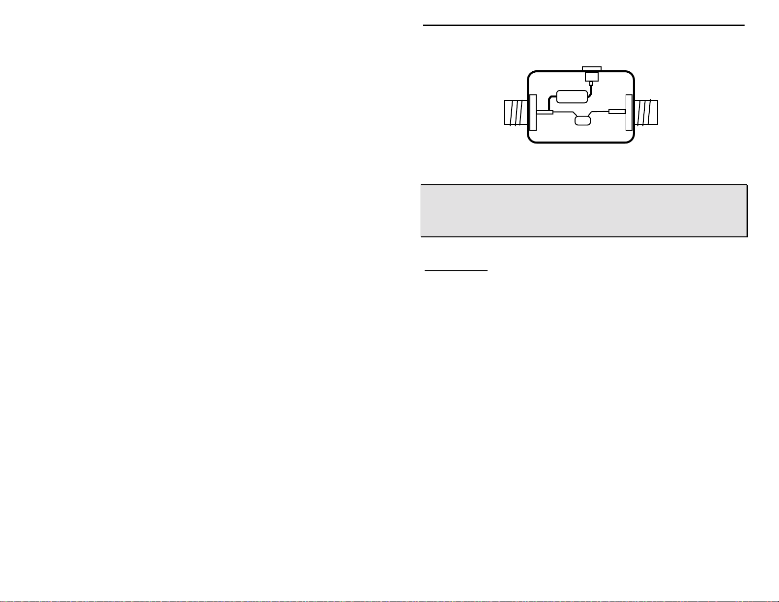
Building a Bias-T:
A technique called "phantom powering" lets you feed the operating voltage
through the c oaxial line between the operating locatio n and antenna. It's done
with a simple device called a "bias-T”. The bias-T piggybacks DC power onto
the coaxial feedline without interfering with VHF signals. Components are
provided in this kit should you wish to build your own bias-T.
As shown below, the bias-T consists of a 2.2-uH choke plus a 100-pF multilayer
capacitor. The 2.2-uH choke (red-red-gold) allows DC current to pass onto the
feedline and, at the same time, prevent VHF signals from getting lost in the
power supply circuitry. Conversely, the 100-pF multilayer capacitor (marked
"101") passes VHF signals into the receiver while blocking DC power from
back-feeding into the radio's antenna jack. Mount bias-T components in an
external project box powered by a small 9 or 12-volt wall adapter (see following
diagram). Use a shielded metal enclosure.
15
Page 18
VEC-1402DK Instruction Manual High Performance 2 Meter Pre-Amp Kit
Power (9-15 VDC)
2.2 uH
Antenna
Receiver
100 pF
Warning--do not reverse direction when installing
Warning: Never reverse-polarize the supply voltage to
your preamp or reverse the direction of
installation of the bias-T. Damage to
electronic components may result.
Important Note:
the preamp is also installed in the line. Most VHF antennas are DC-grounded to
prevent static buildup on the elements. This provision will short circuit the
preamp power supply to ground if the preamp is removed!
Never connect your bias-T module to a VHF antenna unless
Finally, choke RF1 (2.2-uH, red-red-gold) must be installed on the preamp's PC
board whenever the VEC-1402DK is phantom-powered over the coaxial
feedline! This choke, in combination with C9, C10, provides the necessary
network at the preamp end of the feedline to separate DC and RF signal paths.
Balun Option T1:
Virtually all balanced antennas, and many so-called low-cost "unbalanced"
antennas, perform better with a balun installed. Baluns block unwanted
common-mode noise pickup on the outer surface of the coaxial feedline shield.
They also prevent the feedline from interacting with the antenna elements and
disrupting the desired pick-up pattern. The balun used on the VEC-1402DK is
a low-loss, simple coaxial choke that works much the same as the 2.2-uH
molded choke used in the bias-T circuit. The unique thing about a "coaxial
choke" is how it blocks RF energy from flowing on the outside of the cable,
while still allowing desired signals to pass freely inside. Interference and
residential noise traveling up the outside of the feedline are blocked before
reaching the antenna, while weak radio signals picked up by the antenna
elements easily pass down the inside of the cable without attenuation.
To prepare the balun, do the following:
16
Page 19

VEC-1402DK Instruction Manual High Performance 2 Meter Pre-Amp Kit
!
1. Find a 12" length of RGS-316 miniature coaxial cable supplied with your
kit.
!
2. Strip about 1/2" of insulation off each end of the cable, and prepare
pigtails for connection to the PC board, as shown in the drawing below:
!
3. Form the RGS-316 into a 4-turn coil about 3/4" in diameter, and secure
the turns with two (2) plastic tie-wraps provided in your kit.
Tie-Wraps
RG-174
A
!
4. Install the ends of the RGS-316 at T1, as shown in the following diagram,
and solder in place. Note that the coax shield on the L1 side of the balun
(A) should be connected as shown (to the foil or grounded side of the PC
board).
B
W1
L1
W2
T1
GND
B
A
CTR
17
Page 20

VEC-1402DK Instruction Manual High Performance 2 Meter Pre-Amp Kit
Feeding Balanced Antennas with the Balun:
Connect points W1 and W2 on the preamp directly to the antenna feedpoint
without grounding either one. If your box is metal, neither lead should make
electrical contact with it, or the choking action of the balun will be defeated.
Installing the VEC-1402DK in a Radio (and other considerations):
You may install the VEC-1402DK into a VHF receiver, scanner, ham radio
transceiver, or repeater. Use short lengths of RG-174 cable for the RF
connections. The preamp requires a 9 to 15-volt DC power source at
approximately 8 mA, which can usually be borrowed from a convenient point in
the receiver.
Warning: The preamp must never be installed in line
with a transmitter or severe damage may
result!
In a transceiver, you must install the VEC-1402DK between the antenna switch
(pin-diode or mechanical relay) and the radio's receiver circuitry. Amateur radio
Dxers who require a remote antenna mounted receiver preamp must provide
sequenced RF protection to bypass the preamp during transmit periods.
External Power Sources:
Your preamp may be powered from any suitable 9 to 15-volt DC source-including a "wall cube" type supply. However, use caution! The actual voltage
output of a low-cost adapter may be much higher than its rated value when
powering low-current loads. This can damage your preamp. Choose a wall cube
that's both internally regulated and filtered. Models used for charging nicad
batteries may supply pulsating, unregulated and unfiltered DC voltage.
Reversing the voltage polarity of your preamp’s power source could destroy Q1.
A diode in series with the (+) power lead will prevent such damage. This
"protection diode" prevents current from flowing in the wrong direction (a diode
may also be installed in series with the 2.2-uH choke in the bias-T to protect
remote preamps).
1N914 or 1N4001
+
Preamp
-
18
Page 21

VEC-1402DK Instruction Manual High Performance 2 Meter Pre-Amp Kit
IN CASE OF DIFFICULTY:
Preamp Stops Amplifying:
At worst, a working preamp that fails may indicate a failure of transistor Q1.
First make sure the supply voltage and RF cable connections are okay. If the
preamp failed after being installed in a transceiver, the problem may be
excessive transmitter RF “leaking” back into the preamplifier and damaging Q1.
Cannot Align or Test Preamp:
A newly constructed preamp that fails to work requires a careful recheck of all
work. Low gain, or the inability to properly tune the preamp, may indicate
damaged capacitors or parts in the wrong positions on the PC board. A
intermittently operating preamp may have poor solder connections, a problem
with coax connections, or an intermittent power source. Instability, or selfoscillation, may be caused by RF cable problems, or by excessive component
lead lengths on the PC board.
Voltmeter Checks:
With 13.8 volts DC applied to the preamp, the collector voltage on Q1 should
read approximately 9 volts, with the base voltage at 0.76 volts. These voltages
are easily measured at the opposite ends of 100-k bias-resistor R1. They may
vary slightly depending on the individual characteristics of Q1, but large
variations indicate that Q1 or other components are damaged or installed
incorrectly.
When all else fails, please refer to the warranty instructions regarding factory
technical assistance or repair discussed earlier in this manual.
THEORY OF OPERATION AND SPECIFICATIONS
Operation:
Coils L1, L2 and L3, L4 form two High-Q tuned LC bandpass filters. The skirt
selectivity of these dual filters combines to offer an excellent degree of out-ofband signal rejection. This preamp is well-suited for use in strong RF
environments, or for repeater system receiver operation. Q1 is a high-gain lownoise "microwave"-type transistor with good strong-signal handling
characteristics operated as a common-emitter amplifier. It is biased for
minimum noise figure, and normally exhibits a stage-gain of about 15 dB.
Specifications:
Tuning range:..................................136 - 154 MHz
19
Page 22

VEC-1402DK Instruction Manual High Performance 2 Meter Pre-Amp Kit
Gain at 13.8 Vdc: ............................ 15 dB typical
Power requirement:.........................9 - 15 Vdc, 8 mA typical
Input/Output Impedance:.................50 - 75 ohms, Unbalanced coaxial
PC Board.........................................4.000" x 1.500"
20
Page 23

 Loading...