

Page 1

IMPORTANT WARRANTY INFORMATION! PLEASE READ
Return Policy on Kits When Not Purchased Directly From Vectronics: Before continuing
any further with your VEC kit check with your Dealer about their return policy. If your Dealer
allows returns, your kit must be returned before you begin construction.
Return Policy on Kits When Purchased Directly From Vectronics: Your VEC kit may be
returned to the factory in its pre-assembled condition only. The reason for this stipulation is,
once you begin i nsta lli ng a nd sol deri ng pa rt s, you essenti al ly tak e over the rol e of the devic e's
manufacturer . From this point on, neither Vect ronics nor its dea lers can reas onably be held
accountab le for the qua lity or the outcome of your work. Because of this, Vectronics cannot
accept return of any kit-in-progress or completed work as a warranty item for any reason
whatsoever. If you are a new or inexperienced kit b uilder, we urge you to read the manual
carefully a nd determine whether or not you're r eady to tak e on the job. If you wish to c hange
your mind and return your ki t, you may--b ut you must do i t before you begin c ons tr uc ti on, a nd
within ten (10) working days of the time it arrives.
Vectronics Warrants: Your kit contains each item specified in the parts list.
Missing Parts: If you determine, during your pre-construction inventory, that any part is
missing, please contact Vectronics and we'll send the missing item to you free of charge.
However, before you contact Vect ronic s, please look carefully to c onf ir m you haven't misr ea d
the marking on one of the other items provided with the kit. Also, make certain an alternative
part hasn't been substituted for the item you're missing. If a specific part is no longer
available, or if Engineering has determined that an alternative component is more suitable,
Vectronics reserves the right to make substitutions at any time. In most cases, these changes
will be clearly noted in an addendum to the manual.
Defective Parts: Today's electronic parts are physically and electrically resilient, and
defective components a re r a re. However, if you disc over a n it em duri ng your pr e- c onst r uct i on
inventory that's obviously broken or unserviceable, we'll replace it. Just return the part to
Vectronics at the address below accompanied with an explanation. Upon receipt, we'll test it.
If it's defec tive and appear s unused, we'll ship you a new one right away at no charge.
Missing or Defective Parts After You Begin Assembly: Parts and materials lost or
damaged after construction begins are not covered under the terms of this warranty. However,
most parts supplied with VEC kits are relatively inexpensive and Vectronics can replace them
for a reasonable charge. Simply contact the factory with a complete description. We'll
process your order quickly and get you back on trac k.
Factory Repair After You Begin Assembly: Kits-in progress and completed kits are
specifically excluded from coverage by the Vectronics warranty. However, as a service to
customers, tec hnicia ns ar e availa ble t o evaluate a nd repai r malf unctioni ng kits for a minimum
service fee of $18.00 (½ hour rate) plus $7.00 shipping and handling (prices subject to
change). To qualify for repair service, your kit must be fully completed, unmodified, and the
printed circuit board assembled using rosin-core solder. In the event your repair will require
more than an hour to fi x (or $36.00, subject to change), our technicians will contact you in
advance by telephone b efore p erforming t he work. Def ective unit s should b e shipp ed prep aid
to:
Vectronics
300 Industrial Pa rk Road
Starkville, MS 39759
Page 2

When shipping, pack your kit well and include the minimum payment plus shipping and
handling charges ($25.00 total). No work can be performed without pre-payment. Also,
provide a valid UPS return address a nd a day time phone number where you may be reac hed.
Page 3

VEC-1320K/1330K/1340K/1380K Owner's Manual
INTRODUCTION
This inexpensive transceiver kit provides a great first introduction to QRP
operation, one of the hottest and fastest growing activities in amateur radio.
When you build it, you'll discover what thousands of QRP enthusiasts already
know--it doesn't take a degree from MIT to "homebrew" a rig that works!
Indeed, all it takes are a few simple tools and a couple relaxing evenings of your
time. And, once you complete it, you'll quickly unseat another myth--that it
takes a $1000 radio to work DX. The VEC QRP-CW Transceiver Kit is simple
to build and even easier to align. VXO frequency control and broadband
transmitter circuitry eliminate the need for costly alignment equipment or tricky
calibration procedures. Connect an antenna, peak the receiver's front-end
trimmer, and you're ready to go! You'll get microvolt sensitivity and a solid
QRP CW signal with shaped keying. Best of all, you'll experience the
excitement of working other stations using a simple home-built rig you made
with your own two hands!
TOOLS AND SUPPLIES
Construction Area:
area where you can easily organize and handle small parts without losing them.
An inexpensive sheet of white poster board makes an excellent construction
surface and provides protection for the underlying table or desk. Well-diffused
overhead lighting is a plus, and a supplemental high-intensity desk lamp is
especially helpful for close-up work. Safety is always important! Be sure to use
a suitable high-temperature stand for your soldering iron, and keep the work area
free of combustible clutter.
Universal Kit-building Tools:
additional items for completion, virtually all construction projects require a work
area outfitted with the following tools and supplies.
!
30 to 60 Watt Soldering Iron
!
High-temperature Iron Holder with Moist Cleaning Sponge
!
Rosin-core Solder (thin wire size preferred, .031”)
!"
Needle Nose Pliers or Surgical Hemostats
!
Diagonal Cutters or “Nippy Cutters”
!
Solder Sucker (squeeze or vacuum pump type), or Desoldering Braid
!
Bright Desk Lamp
!
Magnifying Glass
Kit construction requires a clean, smooth, and well-lighted
Although your particular kit may require
1
Page 4

VEC-1320K/1330K/1340K/1380K Owner's Manual
Additional Items:
!
RF power meter or VSWR bridge (or LED--any color)
!
50-ohm dummy load (or 1-watt 47 ohm carbon-film resistor)
!
Telegraph key outfitted with a 1/4" monaural phone plug
!
Headphones or extension speaker outfitted with a 1/4" monaural phone plug
!
13.8-v dc power source
!
Antenna cut for band of operation
BEFORE YOU START BUILDING
Experience shows there are four common mistakes builders make. Avoid these,
and your kit will probably work on the first try! Here's what they are:
1. Installing the Wrong Part:
and a 10K resistor may look almost the same, but they may act very
differently in an electronic circuit! Same for capacitors--a device marked
102 (or .001 uF) may have very different operating characteristics from on
marked 103 (or .01uF).
2. Installing Parts Backwards:
capacitors to make sure the positive (+) lead goes in the (+) hole on the
circuit board. Transistors have a flat side or emitter tab to help you identify
the correct mounting position. ICs have a notch or dot at one end indicating
the correct direction of insertion. Diodes have a banded end indicating
correct polarity. Always double-check--especially before applying power to
the circuit!
3. Faulty Solder Connections:
bridges. Cold solder joints happen when you don't fully heat the connection-or when metallic corrosion and oxide contaminate a component lead or pad.
Solder bridges form when a trail of excess solder shorts pads or tracks
together (see Solder Tips below).
4. Omitting or Misreading a Part:
Always double-check to make sure you completed each step in an assembly
sequence.
Soldering Tips:
professional soldering. Before you install and solder each part, inspect leads or
pins for oxidation. If the metal surface is dull, sand with fine emery paper until
shiny. Also, clean the oxidation and excess solder from the soldering iron tip to
allow maximum heat transfer. Allow the tip of your iron to contact both the lead
Cleanliness and good heat distribution are the two secrets of
It always pays to double-check each step. A 1K
Always check the polarity of electrolytic
Inspect for cold-solder joints and solder
This is easier to do than you might think!
2
Page 5
VEC-1320K/1330K/1340K/1380K Owner's Manual
and pad for about one second (count "one-thousand-one") before feeding solder
to the connection. Surfaces must become hot enough for solder to flow
smoothly. Feed solder to the opposite side of the lead from your iron tip--solder
will wick around the lead toward the tip, wetting all exposed surfaces. Apply
solder sparingly, and do not touch solder directly to the hot iron tip to promote
rapid melting.
Desoldering Tips:
these instructions carefully! First, grasp the component with a pair of hemostats
or needle-nose pliers. Heat the pad beneath the lead you intend to extract, and
pull gently. The lead should come out. Repeat for the other lead. Solder may
fill in behind the lead as you extract it--especially if you are working on a
double-sided b o ar d with plat e-thr o ugh hol es. Sho uld this ha pp e n, tr y heat ing the
pad again and inserting a common pin into the hole. Solder won't stick to the
pin's chromium plating. When the pad cools, remove the pin and insert the
correct component. For ICs or multi-pin parts, use desoldering braid to remove
excess solder before attempting to extract the part. Alternatively, a low-cost
vacuum-bulb or spring-loaded solder sucker may be used. Parts damaged or
severely overheated during extraction should be replaced rather than reinstalled.
Work Habits:
instructions and, in many cases, to perform new and unfamiliar tasks. To avoid
making needless mistakes, work for short periods when you're fresh and alert.
Recreational construction projects are more informative and more fun when you
take your time. Enjoy!
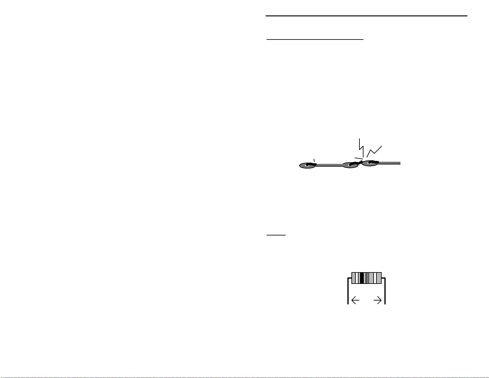
Sorting and Reading Resistors:
a color code (shown below). You don't have to memorize this code to work with
resistors, but you do need to understand how it works:
If you make a mistake and need to remove a part, follow
Kit construction requires the ability to follow detailed
The electrical value of resistors is indicated by
Resistor Color Code
Blue = 6
Violet = 7
Gray = 8
White = 9
Silver = 10%
Gold = 5%
1st Digit
2nd Digit
Multiplier
Tolerence
(gold or silver)
Black = 0 (tens)
Brown = 1 (hundreds)
Red = 2 (K)
Orange = 3 (10K)
Yellow = 4 (100K)
Green = 5 (1Meg)
When you look at a resistor, check its multiplier code first. Any resistor with a
black multiplier band falls between 10 and 99 ohms in value. Brown designates
a value between 100 and 999 ohms. Red indicates a value from 1000 to 9999
ohms, which is also expressed as 1.0K to 9.9K. An orange multiplier band
designates 10K to 99K, etc. To sort and inventory resistors, first separate them
3
Page 6
VEC-1320K/1330K/1340K/1380K Owner's Manual
l
into groups by multiplier band (make a pile of 10s, 100s, Ks, 10Ks, etc.). Next,
sort each group by specific value (1K, 2.2K, 4.7K, etc.). This procedure makes
the inventory easier, and also makes locating specific parts more convenient later
on during construction. Some builders find it especially helpful to arrange
resistors in ascending order along a strip of double-sided tape.
Some VEC kits may contain molded chokes which appear, at first glance, similar
to resistors in both shape and band marking. However, a closer look will enable
you to differentiate between the two--chokes are generally larger in diameter and
fatter at the ends than resistors. When doing your inventory, separate out any
chokes and consult the parts list for specific color-code information.
Reading Capacitors:
value identification. Instead, the value, or a 3-number code, is printed on the
body.
Value Code
10 pF = 100
100 pF = 101
1000 pF = 102
.001 uF = 102*
.01 uF = 103
.1 uF = 104
As with resistors, it's helpful to sort capacitors by type, and then to arrange them
in ascending order of value. Small-value capacitors are characterized in pF (or
pico-Farads), while larger values are labeled in uF (or micro-Farads). The
transition from pF to uF occurs at 1000 pF (or .001 uF)*. Today, most
monolithic and disc-ceramic capacitors are marked with a three-number code.
The first two digits indicate a numerical value, while the last digit indicates a
multiplier (same as resistors).
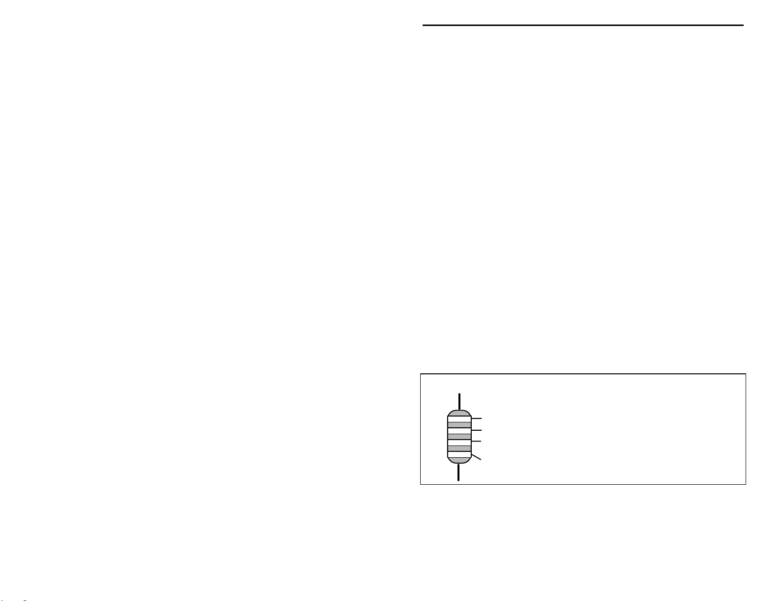
Electrolytic capacitors are always marked in uF. Electrolytics are polarized
devices and must be oriented correctly during installation. If you become
confused by markings on the case, remember the uncut negative lead is slightly
shorter than the positive lead.
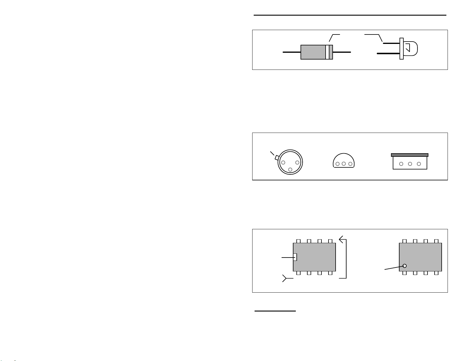
Diodes:
Always look for the banded or cathode end when installing, and follow
instructions carefully.
Diodes are also polarized devices that must be installed correctly.
Unlike resistors, capacitors no longer use a color code for
E
ectrolytic
1 uF
1uF
|
35V
|
-
+
Multilayer
(270 pF)
271
Ceramic Discs
(.001 uF) (.1 uF)
102
104
4
Page 7
VEC-1320K/1330K/1340K/1380K Owner's Manual
Cathode
(shorter Lead)
Diode
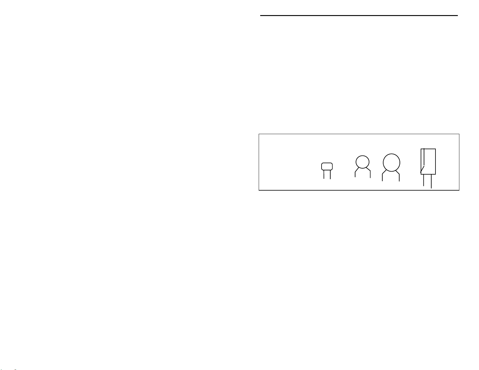
Transistors:
power is applied. Transistors in metal cases have a small tab near the emitter
lead to identify correct positioning. Semiconductors housed in small plastic
cases (TO-92) have an easily-identified flat side to identify mounting orientation.
Many specialized diodes and low-current voltage regulators also use this type
packaging. Larger plastic transistors and voltage regulators use a case backed
with a prominent metal tab to dissipate heat (T-220). Here orientation is
indicated by the positioning of the cooling tab.
Emitter
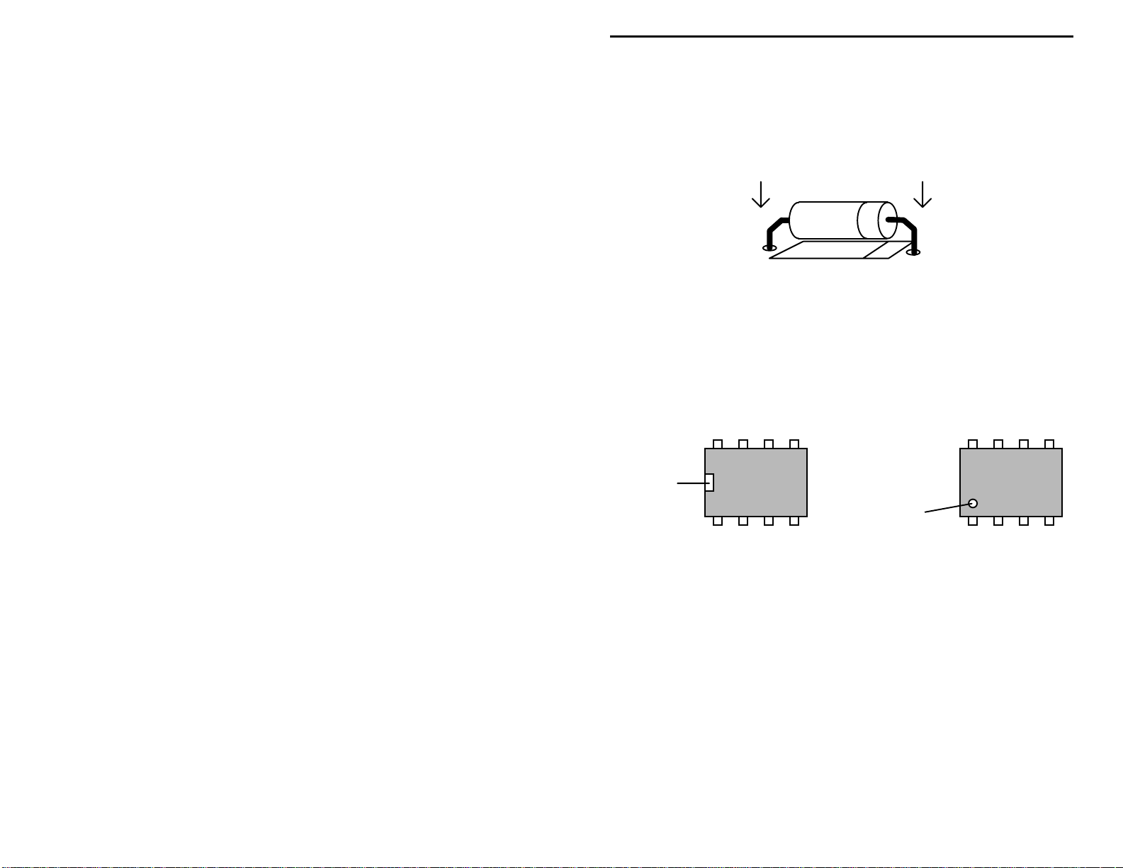
Integrated Circuits:
marking located on one end of the device. A corresponding mark will be silkscreened on the PC board and printed on the kit's parts-placement diagram. To
identify specific IC pin numbers for testing purposes, see the diagram below.
Pin numbers always start at the keyed end of the case and progress counterclockwise around the device, as shown:
If transistors are installed incorrectly, damage may result when
Metal Can Device Plastic Device Tab-cooled Device
Flat Side
Proper IC positioning is indicated by a dot or square
8 7 6 5
LED
Metal Tab
Installation
Key
1 2 3 4
Pin Numbers
Installation
Key
PARTS LIST
The parts list for your kit is presented in two parts. First, you'll identify and
inventory the generic par ts--those items common to all VEC QPR transceiver
5
Page 8

VEC-1320K/1330K/1340K/1380K Owner's Manual
kits regardle ss of band. Then you'll i nventory a bag which contains frequencycritical parts that determine the specific band of operation.
If any parts are missing or damaged, refer to the manual's warranty section for
replacement instructions. If you can't positively identify an unfamiliar item on
the basis of the information given, set it aside until all other items are checked
off. You may then be able to identify it by process of elimination. Finally, your
kit will go together more smoothly if parts are organized by type and arranged by
value ahead of time. Use this inventory as an opportunity to sort and arrange
parts so you can identify and find them quickly during constructio n.
First, locate and identify the generic parts bags. These items are common to all
four models of the VEC QRP-CW Transmitter Kit:
Capacitors:
#
Qty Part Description Designation VEC P/N
!
7 .01 uF ceramic disc (103) C17,C19,C21,C22,
!
2 .05 uF ceramic disc (503) C6,C12 200-2500
!
5 .1 uF ceramic disc (104) C3,C8,C20,C30,C32 200-3100
!
3 1 uF electrolytic C4,C5,C11 270-4100-2
!
1 10 uF electrolytic C7 270-5100-1
!
2 100 uF electrolytic C9,C10 270-6100-1
!
1 12-100 pF trimcap C1 280-2100
!
1 multisection cap C16 281-4010
!
1 tuning shaft for C16 715-2520-
C26,C29,C31
200-2100
0500
Resistors:
#
Qty Part Description Designation VEC P/N
!
2 100 ohm (brown-black-brown) R7,R11 100-2100
!
1 270 ohm (red-violet-brown) R12 100-2270
!
1 470 ohm (yellow-violet-brown) R4 100-2470
!
2 1K ohm (brown-black-red) R3,R8 100-3100
!
2 3.3K ohm (orange-orange-red) R2,R10 100-3330
!
3 10K ohm (brown-black-orange) R5,R6,R14 100-4100
!
2 47K ohm (yellow-violet-orange) R9,R13 100-4470
!
1 1K ohm potentiometer R1 153-3100-1
Diodes:
#
Qty Part Description Designation VEC P/N
!
2 1N4148 silicon switching diode D1,D2 300-4148
!
1 1N4007 rectifier diode D3 300-4007
6
Page 9

VEC-1320K/1330K/1340K/1380K Owner's Manual
Semiconductors:
#
Qty Part Description Designation VEC P/N
!
1 2N3904 NPN transistor Q1 305-3904
!
1 PN2222 NPN transistor Q2 305-2222-1
!
1 2N3053 NPN transistor Q3 305-3055
!
1 2N3906 PNP transistor Q4 305-3906
!
1 SA602A IC U1 325-0602
!
1 LM386 IC U2 324-0386
Other:
#
Qty Part Description Designation VEC P/N
!
2 T50-2 toroid (½" OD red) T1,L4 403-1003
!
1 coaxial-type power jack J1 601-6021
!
1 RCA jack J2 600-0011
!
2 DPDT switch SW1,SW2 504-0022
!
1 6" length of hookup wire 871-2499-
!
1 24" length of #22 wire 870-3022R
!
1 TO-5 heat sink for Q3 750-0194
!
1 VEC-13xx Printed Circuit Board 861-1320
!
1 double-sided tape 781-6312
0600
Now, to complete the inventory, select the list below for the specific model of
your kit--and check off those items:
VEC-1320K 20-Meter Parts Package:
#
Qty Part Description Designation VEC P/N
!
1 2.2 pF ceramic disc (2.2) C13 200-00022
!
1 22 pF multilayer (22 or 220) C15 200-0022
!
2 47 pF multilayer (47 or 470) C2,C18 220-0047
!
1 68 pF multilayer (68 or 680) C25 220-0068
!
3 220 pF multilayer (221) C14,C27,C28 220-0220
!
1 330 pF multilayer (331) C24 220-0330
!
1 470 pF multilayer (471) C23 220-0470
!
2 1.8 uH choke (brown-gray-gold) L2,L3 401-3180
!
1 3.3 uH choke (orange-orange-gold) L1 401-3330
!
1 14.060 MHz crystal Y1 414-06000
VEC-1330K 30-Meter Parts Package:
#
Qty Part Description Designation VEC P/N
!
1 3.3 pF ceramic disc (3.3) C13 200-00033-1
!
1 22 pF multilayer (22 or 220) C15 220-0022
!
2 47 pF multilayer (47 or 470) C2,C18 220-0047
!
1 100 pF multilayer (101) C25 220-0100
7
Page 10

VEC-1320K/1330K/1340K/1380K Owner's Manual
!
3 330 pF multilayer (331) C14,C27,C28 220-0330
!
1 470 pF multilayer (471) C23 220-0470
!
1 680 pF multilayer (681) C24 220-0680
!
2 2.2 uH choke (red-red-gold) L2,L3 401-3220
!
1 3.3 uH choke (orange-orange-gold) L1 401-3330
!
1 10.108 MHz crystal Y1 410-10800
VEC-1340K 40-Meter Parts Package:
#
Qty Part Description Designation VEC P/N
!
1 3.3 pF ceramic disc (3.3) C13 200-00033-1
!
2 47 pF multilayer (47 or 470) C2,C15 220-0047
!
2 100 pF multilayer (101) C18,C25 220-0100
!
1 270 pF multilayer (221) C14 220-0270
!
1 330 pF multilayer (331) C23 220-0330
!
2 470 pF multilayer (471) C27,C28 220-0470
!
1 1000 pF multilayer (1000) C24 220-1010
!
3 4.7 uH choke (yellow-violet-gold) L1,L2,L3 401-3470
!
1 7.040 MHz crystal Y1 405-04000
!
1 24" length of #24 wire 870-3024G
VEC-1380K 80-Meter Parts Package:
#
Qty Part Description Designation VEC P/N
!
1 4.7 pF ceramic disc (4.7) C13 200-00047-1
!
1 68 pF multilayer (68 or 680) C15 220-0068
!
1 100 pF multilayer (101) C18 220-0100
!
1 180 pF multilayer (181) C2 220-0180
!
2 470 pF multilayer (471) C23,C25 220-0470
!
4 820 pF multilayer (821) C14,C24,C27,C28 220-0820
!
3 10 uH choke (brown-black-black) L1,L2,L3 401-4100
!
1 3.5795 MHz crystal Y1 405-0107
!
1 24" length of #24 wire 870-3024G
Once again, if any parts are missing, consult the warranty page on the inside
cover for specific replacement instructions. If your parts inventory is complete,
you're ready to star t buil ding. Re member, o nce c onstr uctio n begins, you may no
longer return your kit.
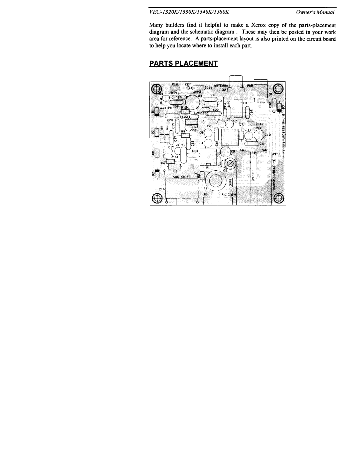
Many builders find it helpful to make a Xerox copy of the parts-placement
diagram and the schematic diagram . These may then be posted in your work
area for reference. A parts-placement layout is also printed on the circuit board
to help you locate where to install each part.
PARTS PLACEMENT
8
Page 11
Page 12
VEC-1320K/1330K/1340K/1380K Owner's Manual
STEP-BY-STEP ASSEMBLY
Your transceiver kit will be constructed in three stages. First, you'll install the
smaller generic parts (resistors, capacitors, etc.) that are common to all four
models. Next, you'll mount frequency-determining components--those parts that
determine the specific band of operation for your particular kit. Finally, you'll
complete the project by installing larger generic parts such as jacks and
switches--things that might get in the way if installed first.
In these instructions, when you see the term install, this means to locate, identify,
and insert the part into its mounting holes on the pc board. This includes prebending or straightening leads as needed so force is not required to seat the part.
Once a component is mounted, bend each lead over to hold it in place. Use
sharp side-cutters to clip off excess lead length before soldering. Make sure
trimmed leads don't touch other pads and tracks, or a short circuit may result:
Good
The term solder means to solder the part's leads in place, and to inspect both (or
all) solder connections for flaws or solder bridges. Nip off excess protruding
leads with a sharp pair of side cutters.
Notice the directions use two sets of check boxes. Check one when a step is
complete and use the other for double-checking your work before operation.
Stage 1
This kit contains 13 fixed-value 1/4 watt resistors. Begin construction by
mounting these first, starting with the smallest value and moving to the largest.
Before installing each one, carefully bend both leads to form right-angles, as
shown below:
When installing resistors, save a few of the clipped-off lead ends--you'll need
these for pc board jumpers later on.
: Small Generic Parts
Not Good
.4"
Find two (2) 100 ohm resistors (brown-black-brown).
10
Page 13

VEC-1320K/1330K/1340K/1380K Owner's Manual
! !
1."Install a 100 ohm resistor at R7 and solder.
! !
2."Install a 100 ohm resistor at R11 and solder.
! !
3."Find the 270 ohm resistor (red-violet-brown). Install at R12 and
solder.
! !
4."Find the 470 ohm resistor (yellow-violet-brown). Install at R4 and
solder.
Find two (2) 1K resistors (brown-black-red).
! !
5."Install a 1K resistor at R3 and solder.
! !
6."Install a 1K resistor at R8 and solder.
Find two (2) 3.3K resistors (orange-orange-red).
! !
7."Install a 3.3K resistor at R2 and solder.
! !
8."Install a 3.3K resistor at R10 and solder.
Find three (3) 10K resistors (brown-black-orange).
! !
9."Install a 10K resistor at R5 and solder.
! !
10."Install a 10K resistor at R6 and solder.
! !
11."Install a 10K resistor at R14 and solder.
Find two (2) 47K resistors (yellow-violet-orange).
! !
12."Install a 47K resistor at R9 and solder.
! !
13."Install a 47K resistor at R13 and solder.
This completes installation of the 13 fixed-value resistors supplied with the kit.
Take a moment to inspect your solder connections and to confirm each resistor
has been installed in the right pc board location. Next, you'll install the kit's 14
disc ceramic capacitors.
Locate seven (7) .01 uF disc ceramic capacitors (marked 103).
! !
14."Install .01 uF at C17 and solder.
! !
15."Install .01 uF at C19 and solder.
! !
16."Install .01 uF at C21 and solder.
! !
17."Install .01 uF at C22 and solder.
! !
18."Install .01 uF at C26 and solder.
! !
19."Install .01 uF at C29 and solder.
11
Page 14

VEC-1320K/1330K/1340K/1380K Owner's Manual
! !
20."Install .01 uF at C31 and solder.
Locate two (2) .05 uF disc ceramic capacitors (marked 503).
! !
21."Install .05 uF at C6 and solder.
! !
22."Install .05 uF at C12 and solder.
Locate five (5) .1 uF disc ceramic capacitors (marked 104).
! !
23."Install .1 uF at C3 and solder.
! !
24."Install .1 uF at C8 and solder.
! !
25."Install .1 uF at C20 and solder.
! !
26."Install .1 uF at C30 and solder.
! !
27."Install .1 uF at C32 and solder.
Your kit also contains six electrolytic capacitors.
and must be installed the correct way in order to work.
mounting hole is noted on both the circuit board and parts placement diagram. If
the markings on the capacitor body are unclear, the plus (+) lead is always the
longer of the two.
Locate three (3) 1 uF electrolytic capacitors.
! !
28."Install 1 uF at C4 and solder.
! !
29."Install 1 uF at C5 and solder.
! !
30."Install 1 uF at C11 and solder.
! !
31."Find a 10 uF electrolytic capacitor. Install at C7 and solder.
Locate two (2) 100 uF electrolytic capacitors.
! !
32."Install 100 uF at C9 and solder.
! !
33."Install 100 uF at C10 and solder.
This completes capacitor installation for now. Take a moment to double-check
capacitor location and electrolytic polarity. Electrolytics must be installed
correctly in order to work. Also, note there are several fixed-value capacitors
remaining in your kit. These will be installed later as frequency-determining
parts. Finally, the VXO variable capacitor (C16) and adjustable trimmer (C1)
will be installed last because of their larger size.
Electrolytic caps are polarized
The capacitor's plus (+)
Now that you've accumulated a collection of nipped-off lead-ends, this is a good
time to install the board's five (5) jumper leads. Each should be pre-formed prior
12
Page 15
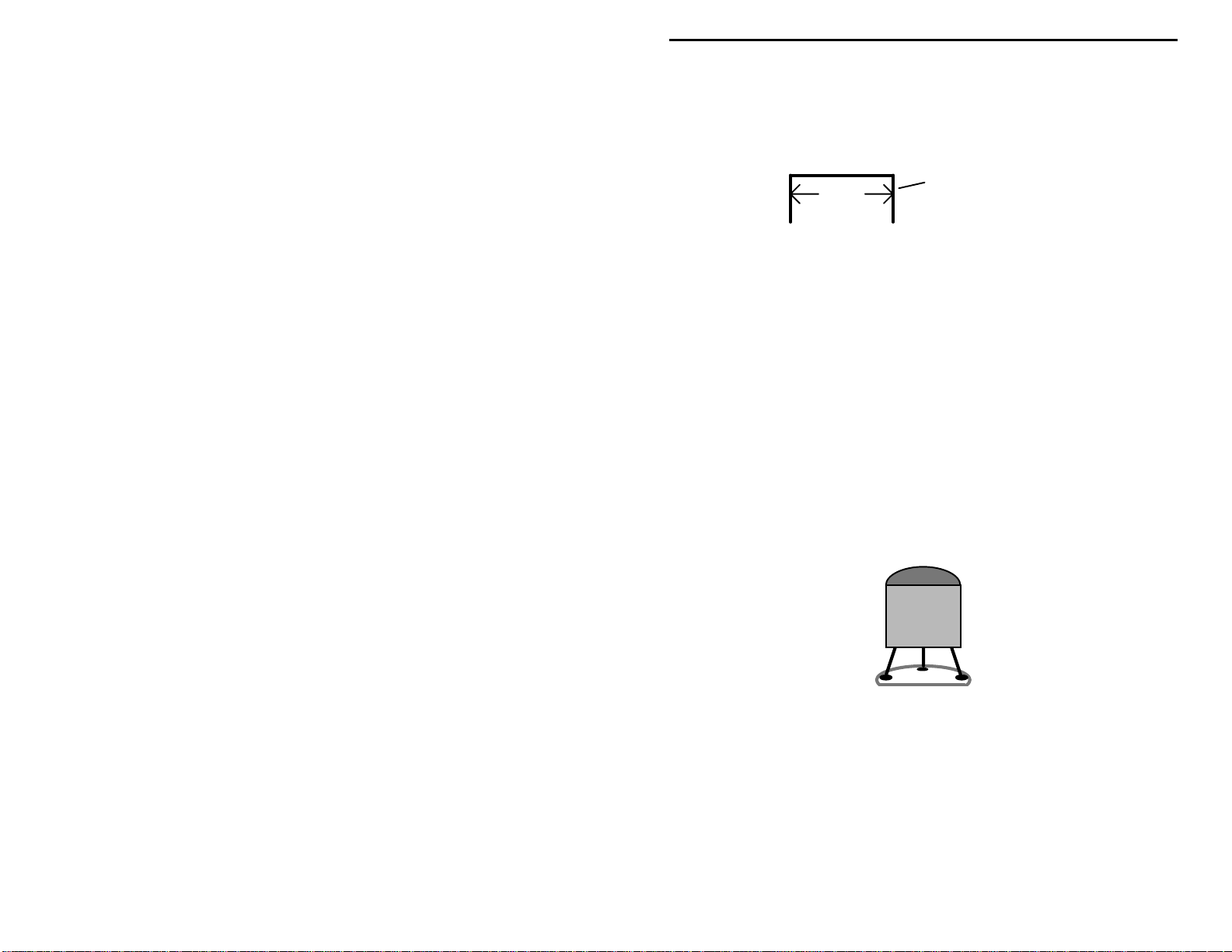
VEC-1320K/1330K/1340K/1380K Owner's Manual
to installation, as shown below. The approximate distance between mounting
holes is given for each to help you pre-form them. When installed, each jumper
should lay flat against the PC board.
span
! !
34."Form a .275" jumper and install at JMP1.
! !
35."Form a .225" jumper and install at JMP2.
! !
36."Form a .425" jumper and install at JMP3.
! !
37."Form a .5" jumper and install at JMP4.
! !
38."Form a .5" jumper and install at JMP5.
Save one additional resistor lead for connecting variable capacitor C16 later on.
Next, install the kit's transistors and diodes.
critical--they must be oriented correctly.
! !
39."Locate the 2N3906 transistor (black plastic case), checking
identification markings closely. Find its flat side and align with the
printed outline on the pc board before inserting the leads. Install the
2N3906 at Q4 and solder.
discarded lead end
Positioning of these parts is
2N3906
E B C
! !
40."Locate a 2N3904 transistor (black plastic case). Install at Q1 and
solder.
! !
41."Locate a PN2222 transistor (black plastic case). Install at Q2 and
solder.
! !
42."Find the 2N3053 transistor (metal case). Install at Q3, inserting leads
all the way so the metal case rests against the pc board surface. The
metal "emitter" tab should point toward C29. Solder.
13
Page 16
VEC-1320K/1330K/1340K/1380K Owner's Manual
Locate two (2) 1N4148 diodes. The 1N4148 has a small glass body with a black
band at one end. When installing, position this band to correspond with the
marking on the pc board.
! !
43."Install a 1N4148 at D1, observing the position of the band. Solder.
! !
44."Install a 1N4148 at D2, observing the position of the band. Solder.
! !
45."Locate the 1N4007 diode (larger body). Observing polarity, install at
D3 and solder. Save the clipped-off lead ends--these will be installed
to support VXO capacitor C16 later on.
Find U1, a NE602 8-pin IC (integrated circuit). Look for the markings
"NE602AN”, or other similar nomenclature such as “SA602”. Note that the IC
body has a small notch or dimple called a installation key molded at one end.
Inspect and straighten any bent pins prior to installation.
8 7 6 5
Installation
Key
1 2 3 4
Pin Numbers
! !
46."Align the NE602 so the installation key corresponds with markings on
the pc board at U1. Carefully insert the pins into the mounting holes
provided, seating the device firmly in place. Confirm all pins protrude
through the b oar d, and that no ne were b ent o ver d uring i nserti on. T he
keyed end should be positioned toward the front of the pc board.
Installation
Key
! !
47."Solder U1.
! !
48."Locate the LM386 Audio Amplifier IC. Identify the keyed end and
carefully install at U2. They keyed end should be toward the back of
the board.
! !
49."Solder U2.
14
Page 17
VEC-1320K/1330K/1340K/1380K Owner's Manual
This concludes the first phase of construction (small generic parts). Next, you'll
install frequency-determining components. However, before you start, this
might be a good time to take a well-deserved break! Be sure to check transistor
and diode positioning and polarity before moving on.
Stage 2
In this section, you'll select a specific set of instructions for your particular kit.
However, before you do this, please review these two important general
construction tips that apply to all four versions.
Installing Multilayer Capacitors:
kit. A multilayer cap is similar to a surface-mount "chip" capacitor, except that
it has a lead spot-welded onto each end of the capacitor body. Each cap is then
coated with an epoxy coating. Multilayers have superior radio-frequency
operating characteristics, but the lead welds may fail if the leads are placed
under stress while being heated during installation or removal. For this reason,
never use force to seat a multilayer cap into the PC board. If the spacing isn't
right, pre-form the leads to the correct spacing before installation!
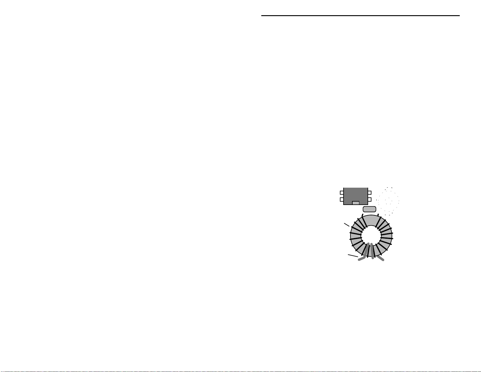
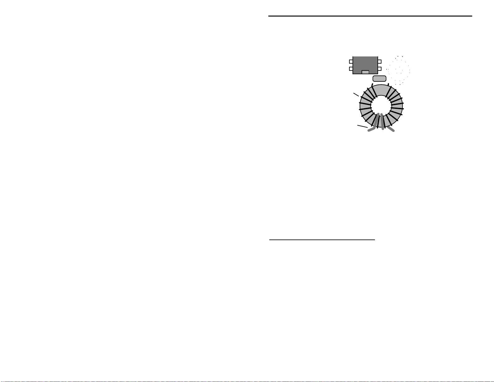
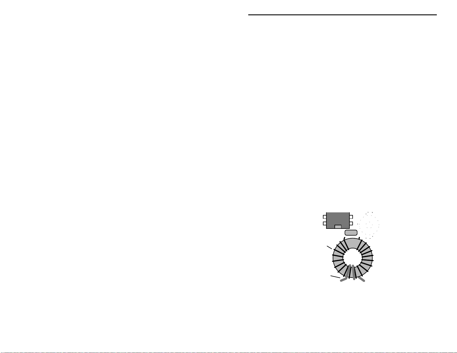
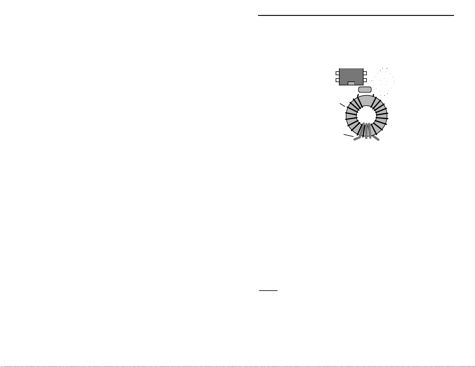
Winding T1 and L4:
low-pass filter each use a high-Q toroid inductor wound on a T50-2 form (T50
means the form is .50" in diameter and 2 designates the "mix" of powdered iron
used to make it). When winding toroid coils, remember the number of turns are
counted inside the form. This means, if the instructions call for a 12-turn coil,
you must pass the wire through the ce nter of the core 12 times. When winding
these coils, be sure to pull each turn up tight before starting the next. If the coil
is wound loosely, inductance increases. At L4, this could reduce transmitter
output power.
: Frequency-Determining Parts
There are 9 multilayer capacitors in your
Incorrect
The receiver's pre-selector circuit and the transmitter's
Ooops!
Correct
15
Page 18

VEC-1320K/1330K/1340K/1380K Owner's Manual
Count turns on inside of form.
Pull each turn tight before winding the next.
Tin leads with solder before installing.
Before installing T1 or L4 on the pc board, be sure to tin both coil leads with
solder. The coil wire provided with your kit is coated with heat-stripable enamel
insulation that breaks down at soldering-iron temperatures. If you touch the tip
of an iron to the end of the wire for several seconds, the insulation should start to
melt, allowing solder to adhere to the copper underneath. If your iron isn't hot
enough to start this process, carefully scrape off insulation with a small hobby
knife before attempting to tin.
If necessary, refer back to these instructions at any time during assembly. You
may now move ahead to the section of the manual that corresponds with your
particular kit.
VEC-1320K 20-Meter Transceiver Kit
! !
1."Find the 2.2 pF disc ceramic capacitor (2.2). Install at C13 and solder.
! !
2."Find the 22 pF multilayer cap (marked 22 or 220). Install at C15 and
solder.
Find two (2) 47 pF multilayer cap (47 or 470).
! !
3."Install a 47 pF at C2.
! !
4."Install a 47 pF at C18.
! !
5."Find the 68 pF multilayer cap (68 or 680). Install at C25 and solder.
Find three (3) 220 pF multilayer caps (marked 221).
! !
6."Install a 220 pF multilayer at C14 and solder.
! !
7."Install a 220 pF multilayer at C27 and solder.
! !
8."Install a 220 pF multilayer at C28 and solder.
! !
9."Find the 330 pF multilayer cap (marked 331). Install at C24 and
solder.
! !
10."Find the 470 pF multilayer cap (471). Install at C23 and solder.
16
Page 19
VEC-1320K/1330K/1340K/1380K Owner's Manual
Locate two (2) 1.8 uH chokes (brown-gray-gold-silver or gold).
! !
11."Install a 1.8 uH at L2 and solder.
! !
12."Install a 1.8 uH at L3 and solder.
! !
13. Find the 3.3 uH (orange-orange-gold-silver or gold). Install at L1 and
solder.
Locate two T50-2 toroid coil forms (a donut-shaped part about ½" in diameter
and color-coded red). Also, find the #22 enameled coil wire provided with your
kit.
! !
14. Wind twenty (20) turns of #22 enameled wire onto the T50-2 form.
Note that turns are counted inside the form, and each turn is pulled
tight before winding the next. Sp read the windings out, distributing
over 80% of the form's circumference.
! !
15. Trim each coil lead to ½" in length and tin with solder.
! !
16. Wind a two-turn secondary link of hook-up wire over the center
portion of t he primary winding (two turns p assing through the center ).
Install at T1, laying flat--as shown below. Save unused portion of
insulated wire--you will need 4" of insulated wire later.
Primary
Link
! !
17. Solder T1 in place.
! !
18. Wind 10 turns of #22 enameled wire on a T50-2 toroid form. Spread
windings for 80% coverage, and install at L4 in an upright position.
! !
19. Solder L4 in place.
! !
20. Locate the 14.060 MHz crystal (metal can, two wire leads). Install at
Y1 and solder.
17
Page 20

VEC-1320K/1330K/1340K/1380K Owner's Manual
This completes stage 2 construction of the VEC-1320K
checking for er rors, you may now move on to the fi nal stage of construction.
VEC-1330K 30-Meter Transceiver Kit
! !
1. Find the 3.3 pF disc ceramic capacitor (3.3). Install at C13 and solder.
! !
2. Find the 22 pF multilayer capacitor (22 or 220). Install at C15 and
solder.
Find two (2) 47 pF multilayer capacitors (47 or 470).
! !
3. Install a 47 pF at C18 and solder.
! !
4. Install a 47 pF at C2 and solder.
! !
5. Find the 100 pF multilayer capacitor (101). Install at C25 and solder.
Find three (3) 330 pF multilayer capacitors (331).
! !
6. Install a 330 pF at C14 and solder.
! !
7. Install a 330 pF at C27 and solder.
! !
8. Install a 330 pF at C28 and solder.
! !
9. Find the 470 pF multilayer capacitor (471). Install at C23 and solder.
! !
10. Find the 680 pF multilayer capacitor (681). Install at C24 and solder.
Find two (2) 2.2 uH molded chokes (red-red-gold-silver or gold)
20-meter kit
After
.
! !
11. Install a 2.2 uH at L2 and solder.
! !
12. Install a 2.2 uH at L3 and solder.
! !
13. Find the 3.3 uH molded choke (orange-orange-gold-silver or gold).
Install at L1 and solder.
Locate two T50-2 toroid coil forms (½" donut-shaped form, red color code).
Also, find the #22 enameled coil wire provided with your kit.
! !
14. Wind twenty-five (25) turns of #22 enameled wire onto the T50-2
form. Note that turns are counted inside the form, and each turn is
pulled tight before winding the next. Spread the windings out,
distributing over 80% of the form's circumference.
! !
15. Trim each coil lead to ½" in length and tin with solder.
! !
16. Wind a two-turn secondary link of hook-up wire over the center
portion of t he primary winding (two turns p assing through the center ).
18
Page 21
VEC-1320K/1330K/1340K/1380K Owner's Manual
Install at T1, laying flat--as shown below. Save unused portion of
insulated wire--you will need 4" of insulated wire later.
Primary
Link
! !
17. Solder T1 in place.
! !
18. Wind 12 turns of #22 enameled wire on a T50-2 toroid form. Spread
windings for 80% coverage, and install at L4 in an upright position.
! !
19. Solder L4 in place.
! !
20. Locate the 10.108 MHz crystal (metal can, two wire leads). Install at
Y1 and solder.
This completes stage 2 construction of the VEC-1330K
30-meter kit
After
.
checking for er rors, you may now move on to the fi nal stage of construction.
VEC-1340K 40-Meter Transceiver Kit
! !
1. Find the 3.3 pF disc ceramic capacitor (3.3). Install at C13 and solder.
Locate two (2) 47 pF multilayer capacitors (47 or 470).
! !
2. Install a 47 pF at C2 and solder.
! !
3. Install a 47 pF at C15 and solder.
Locate two (2) 100 pF multilayer capacitors (101).
! !
4. Install a 100 pF at C18 and solder.
! !
5. Install a 100 pF at C25 and solder.
! !
6. Find the 270 pF multilayer capacitor (271). Install at C14 and solder.
! !
7. Find the 330 pF multilayer capacitor (331). Install at C23 and solder.
19
Page 22
VEC-1320K/1330K/1340K/1380K Owner's Manual
Locate two (2) 470 pF multilayer capacitors (471).
! !
8. Install a 470 pF at C27 and solder.
! !
9. Install a 470 pF at C28 and solder.
! !
10. Find the 1000 pF (or .001 uF) multilayer capacitor (102). Install at
C24 and solder.
Find three (3) 4.7 uH molded chokes (yellow-violet-gold, silver or gold)
! !
11. Install a 4.7 uH at L1 and solder.
! !
12. Install a 4.7 uH at L2 and solder.
! !
13. Install a 4.7 uH at L3 and solder.
Locate two T50-2 toroid coil forms (½" donut-shaped form, red color code).
Also, find the #24 enameled coil wire provided with your kit.
! !
14. Wind thirty (30) turns of #24 enameled wire onto the T50-2 form.
Note that turns are counted inside the form, and each turn is pulled
tight before winding the next. Sp read the windings out, distributing
over 80% of the form's circumference.
! !
15. Trim each coil lead to ½" in length and tin with solder.
! !
16. Wind a two-turn secondary link of hook-up wire over the center
portion of t he primary winding (two turns p assing through the center ).
Install at T1, laying flat--as shown below. Save unused portion of
insulated wire--you will need 4" of insulated wire later.
Primary
Link
! !
17. Solder T1 in place.
Find the #22 wire.
! !
18. Wind 16 turns of #22 enameled wire on a T50-2 toroid form. Spread
windings for 80% coverage, and install at L4 in an upright position.
20
Page 23

VEC-1320K/1330K/1340K/1380K Owner's Manual
! !
19. Solder L4 in place.
! !
20. Locate the 7.040 MHz crystal (metal can, two wire leads). Install at
Y1 and solder.
This completes stage 2 construction of the VEC-1340
checking for er rors, you may now move on to the fi nal stage of construction.
VEC-1380K 80-Meter Transceiver Kit
! !
1. Find the 4.7 pF disc ceramic capacitor (4.7). Install at C13 and solder.
! !
2. Find the 68 pF multilayer capacitor (68 or 680). Install at C15 and
solder.
! !
3. Find the 100 pF multilayer capacitor (101). Install at C18 and solder.
! !
4. Find the 180 pF multilayer capacitor (181). Install at C2 and solder.
Locate two (2) 470 pF multilayer capacitors (470).
! !
5. Install a 470 pF at C23 and solder.
! !
6. Install a 470 pF at C25 and solder.
Locate four (4) 820 pF multilayer capacitor (821).
! !
7. Install a 820 pF at C14 and solder.
! !
8. Install a 820 pF at C24 and solder.
! !
9. Install a 820 pF at C27 and solder.
! !
10. Install a 820 pF at C28 and solder.
Locate three (3) 10 uH molded chokes (brown-black-black-gold or silver).
40-meter kit
After
.
! !
11. Install a 10 uH choke at L1 and solder.
! !
12. Install a 10 uH choke at L2 and solder.
! !
13. Install a 10 uH choke at L3 and solder.
Locate two T50-2 toroid coil forms (½" donut-shaped form, red color code).
Also, find the #24 enameled coil wire provided with your kit.
! !
14. Wind forty (40) turns of #24 enameled wire onto the T50-2 form.
Note that turns are counted inside the form, and each turn is pulled
tight before winding the next. Sp read the windings out, distributing
over 80% of the form's circumference.
! !
15. Trim each coil lead to ½" in length and tin with solder.
21
Page 24
VEC-1320K/1330K/1340K/1380K Owner's Manual
! !
16. Wind a three-turn secondary link of hook-up wire over the center
portion of t he primary winding (two turns p assing through the center ).
Install at T1, laying flat--as shown below. Save unused portion of
insulated wire--you will need 4" of insulated wire later.
Primary
Link
! !
17. Solder T1 in place.
Find the #22 wire.
! !
18. Wind 20 turns of #22 enameled wire on a T50-2 toroid form. Install at
L4 in an upright position.
! !
19. Solder L4 in place.
! !
20. Locate the 3.579 MHz crystal (metal can, two wire leads). Install at
Y1 and solder.
This completes stage-2 construction of the
80-meter kit
. After checking for
errors, you may now move on to the final stage of construction.
Stage 3
: Completing your Kit
During this final stage of construction, you'll install the remaining larger
components. From now on, your transceiver will take shape very quickly!
Locate two (2) DPDT push-button switches.
! !
1. Install a DPDT switch at SW1 and solder in place.
22
Page 25
VEC-1320K/1330K/1340K/1380K Owner's Manual
y
! !
2. Install a DPDT switch at SW2 and solder in place.
! !
3. Locate the 100 pF trimcap. Install at C1 and solder.
! !
4. Locate the RCA pc mounted jack. Install at J2 and solder all tabs in
place.
! !
5. Locate the 2.1 mm DC power jack. Install at J1, seating the case flat
against the surface of the pc board. Twist each solder tab slightly to
secure the jack place, and solder all three.
! !
6. Locate a length of insulated hook-up and prepare two (2) 2" lengths.
! !
7. Install one wire at the "Key" pad and solder.
! !
8. Install one wire at the "Speaker" pad and solder.
Find the plastic-encased variable capacitor. T his is the transmitter's VXO tuning
control (C16).
Locate the small strip of double-sided tape. Also, find the two heavy-gauge
leads removed from the 1N4007 diode. These items will be used to secure C16
in place.
! !
9. Using scissors or a hobby knife, cut a ½" by ¾" square of double-sided
tape. Install this within the box printed at C16 on the pc board (see
diagram).
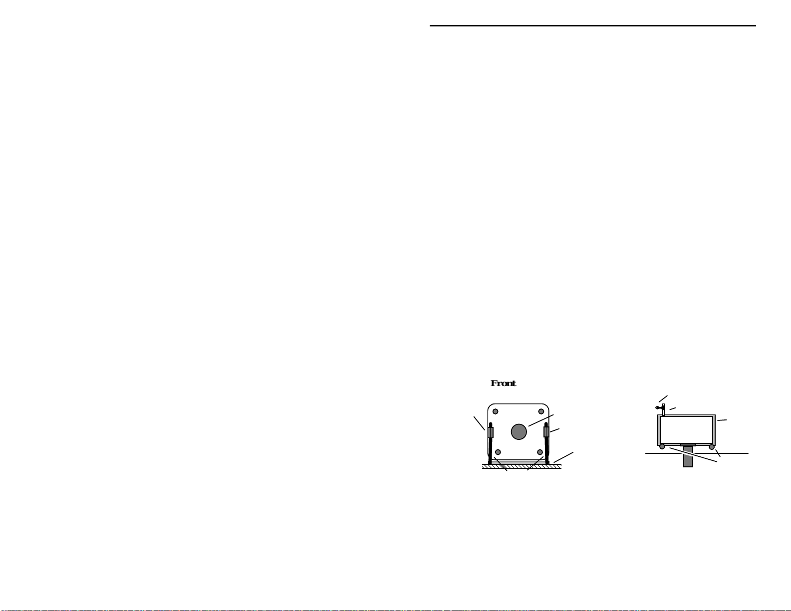
To orient the variable capacitor for installation, use the following diagram.
There should be a ground tab to the left and right of the shaft. At the rear of the
cap, a solder tab will protrude from the case at lower left. When the cap is
positioned as shown, press it down onto the tape to secure it in place.
Top View
C16 connection
Tab
VXO
Capacitor
Tape
Ground
Tabs
Ground Tab
Front View
VXO Capacitor
Leads
Heav
Shaft
Ground Tab
Double-sided Tape
! !
10. Install two (2) heavy leads (from the 1N4007 diode) from the ground
tabs to the pads provided on the front of the pc board. Solder each
lead at both ends. The combined holding action of the two-sided tape
and the ground leads should anchor the cap firmly in place. Rotate the
cap through its range--the c apacitor should not shift position.
23
Page 26
VEC-1320K/1330K/1340K/1380K Owner's Manual
! !
11. Find a resistor lead clipping. Install this between the C16 connection
pad and the nearest solder-tab on the rear of C16. Solder at both ends.
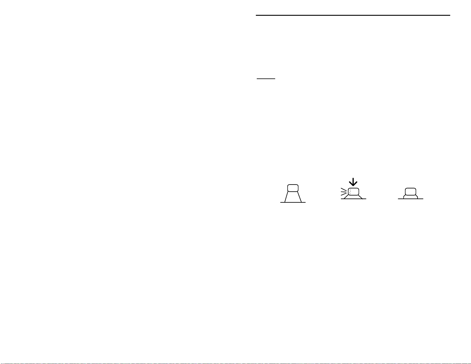
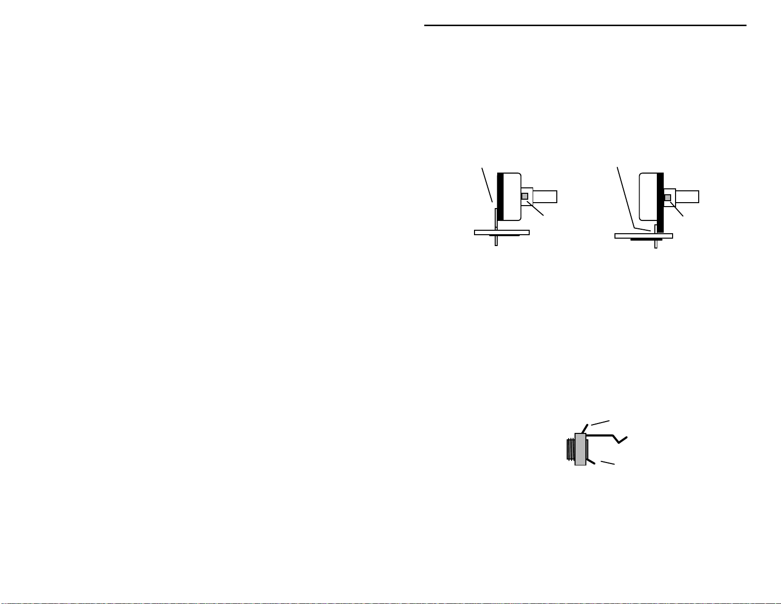
Locate the 1K potentiometer. Before installing, inspect the type of
potentiometer supplied with your kit. If the pins are located on the front side of
the pot, use the front set of mounting holes on the PC board for installation. If
the pins are on the rear, use the rear set of mounting holes (see following
diagram). Also, using side cutters, remove the key tab from the side of the pot
prior to installation.
Rear pins use rear holes.
Nip off tab.
! !
12. Install the 1K potentiometer at R1 and solder.
! !
13. Find the tuning sha ft for C16. Install using a small a mount of contac t
cement or super glue.
! !
14. Find the TO-5 type clip-on heat sink for Q4. Slip this over the
2N3053 transistor.
The custom enclosure for your VEC-13xxK kit (VEC-1300KC) includes two
1/4" monaural phone jacks for the key line and the speaker. Use the following
steps to install the 1/4" jacks. If you have chosen to use your own jacks, now is
a good time to connect them.
! !
15. Locate two (2) 1/4" monaural phone jacks. Identify the plug-tip or
center-connection terminal (as shown in following diagram).
This jack is supplied with
the VEC-1300KC enclosure.
Front pins use front holes.
Nip off tab.
Center connection (wire)
Common connection (case)
! !
16. Identify the free end of the "key" hook-up wire. Connect to the centerconnection terminal of one 1/4" jack.
! !
17. Identify the free end of the "speaker" hook-up wire. Connect to the
center-connection terminal of the other 1/4" jack.
Congratulations--this concludes construction your Vec tronics QRP tr ansceiver.
24
Page 27

VEC-1320K/1330K/1340K/1380K Owner's Manual
You deserve a well-earned break! When you come back, give your work a
thorough "QC" quality-control check before moving on to the testing and
alignment section.
TESTING AND ALIGNMENT
PC Board Inspection:
QC (quality control) inspection. This will help you find inadvertent assembly
errors that might prevent the radio from working or cause damage to sensitive
parts. Follow this procedure:
!
Compare parts locations against the parts-placement diagram. Was each
part installed where it is supposed to be? Was the correct value used? Start
at one side of the board and work your way across in an organized pattern.
!
Inspect the solder side of the board for cold-solder joins and solder bridges
between tracks or pads. Use a magnifying glass to obtain a clear view of the
track area. If you suspect a solder bridge, hold the board in front of a bright
light for a better view. All joints should be smooth and shiny, indicating
good solder wetting and flow. Resolder any beaded or dull-appearing
connections.
Before ap plying power to your kit, give it a thorough
25
Page 28

VEC-1320K/1330K/1340K/1380K Owner's Manual
!
Finally, check the electrolytic capacitor and diodes for correct polarity.
Does the plus (+) polarity symbol on the part agree with the pictorial and
with the pattern on the PC board? How about the diode bands? Were Q1Q4 all installed correctly? Are the ICs installed the right way?
Be sure to correct all errors before moving on. If a careful inspection revealed
that everything is OK , you're now ready for the moment of truth!
Tools and Materials Required for Testing:
Your VEC transceiver uses a "no-tune" design with only one adjustable
alignment trimmer. However, to ensure everything is working correctly, you'll
need to run some initial tests. This requires the following items:
1. 50-ohm dummy load:
resistor capable of handling one watt, will provide a satisfactory transmitter
termination for testing. Two (2) 100-ohm 1-watt metal oxide resistors
(RadioShack 271-152) connected in parallel across a standard RF connector
work well.
2. Power Meter:
confirm the actual output power of your transmitter. If you don't have a
wattmeter, a standard 5mm LED will provide a rough indication of RF
output (see instructions).
3. Telegraph Key:
electronic keyers. To plug in, you'll need a standard 1/4" monaural plug.
Ground (or common) is connected to the plug's outer sleeve, and the key line
is connected to the plug's tip.
3.5 mm Phone Plug
Sleeve
Tip
A dummy load, or any 47 to 51 ohm non-inductive
PL258
100 ohm
100 ohm
If you have access to a sensitive power meter, this will
The transmitter's keying circuit works with manual keys or
Key
26
Ring (not used)
Page 29

VEC-1320K/1330K/1340K/1380K Owner's Manual
4. Power Supply:
power source. Avoid using poorly-regulated or inadequately-filtered 12-volt
wall-adapters. These can generate ripple on the CW note, and may even
damage your kit if the unloaded output exceeds 15 volts. A fully-charged 12volt battery is also a suitable power source, altho ugh transmitter output may
be reduced slightly (RF output is specified at 13.8 volts).
The power jack supplied with your kit is a common 2.1-mm DC connector. The
mating 5.0-mm OD x 2.1-mm ID plugs are available at your local RadioShack
store (274-1567). Take care not to reverse-connect the power leads.
(+) or red power supply lead connects to the center pin, and the minus (-) or
black lead connects to the outer sleeve.
confirm polarity with a voltmeter before installing the plug!
Use any well-regulated 12-14 volt 500-mA DC (or 0.5 A)
The plus
If your power wires aren't color-coded,
DC Power Supply
+
-
Important Note:
protected against major damage by a "crowbar" diode (D1). However, activation
will blow a "trace fuse" etched onto the circuit board next to the power connector.
This must be replaced by a thin wire or a pig-tail type fuse before your kit will
operate again (see "In Case of Difficulty").
In case of accidental reverse-power connection, your kit is
+
-
13.8V @ 0.5A
5. RF Cables:
catalog number 278-208 from Radio Shack. This "Motorola" adapter
requires minor modification to work with RCA jacks. To modify, shorten the
protruding center pin so that it extends about 1/8" beyond the outer sleeve of
the plug using a fine-toothed hack-saw or hobby saw. De-burr and round off
the end. The modified transition will now plug directly into RCA jacks.
Test Set-up and Procedure:
For a direct PL-238 transition, use a scanner adapter plug,
Cut pin here and round off end.
27
Page 30

VEC-1320K/1330K/1340K/1380K Owner's Manual
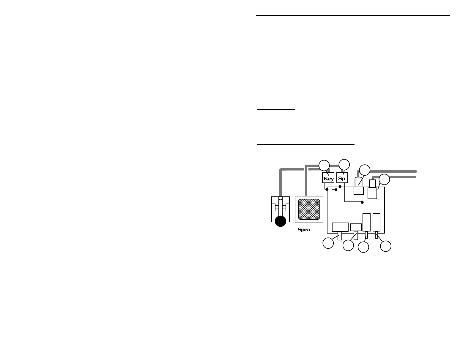
To test your transceiver, set up as shown in the following diagram. Make sure
the pc board is on a clean non-metallic surface free of lead-clippings, hardware,
and other conductive debris that could get underneath and cause a short circuit.
Before connecting the power supply, make sure the power switch (SW1) and
T/R switch (SW2) are in the out position. If you have a station receiver
available, place it in the CW mode and tune it to the transceiver's approximate
operating frequency. This will enable you to monitor your transmitter's signal
during testing. If any of the steps outlined below fail, refer to the "In Case of
Difficulty" section of the manual.
Key
Speaker
Key Sp
VXO
ANT
PWR
J2
J1
RF
PWR T/R
Power Supply
Dummy Load
RF Wattmeter
To test the radio outside of a metal case, you'll need to install temporary
"ground" or "common" leads for the key and speaker jacks. Use temporary
lenghts of hookup wire o r clipleads to make these conne ctions. These may be
attached to any convenient point on the pc board ground surface.
1. Install a temporary lead from the key jack "common" tab to pc board ground.
2. Install a temporary lead from the speaker jack "common" tab to pc board
ground.
3. Press power switch SW1 to ON.
4. Turn RF Gain R1 fully clockwise--you should hear speaker background
noise.
The next steps confirm transmitter operation. If you don't have access to a lowpower RF wattmeter, install a standard 5 mm LED across the antenna jack (J2).
Note that the antenna jack must also be terminated with a 50-ohm dummy load--
the LED is not a substitute for a 50-ohm load. When transmitting, the LED
should illuminate brightly at 1-2 watts output.
5. Press T/R (transmit/receive) switch (SW2) into the transmit position.
28
Page 31

VEC-1320K/1330K/1340K/1380K Owner's Manual
6. Press the key. The power meter (or LED) should indicate output of 1 watt or
more.
7. Release the key--the output power should drop to zero.
If you have a station receiver available, tune it to the transceiver's operating
frequency.
8. Set the VXO capacitor (C16) to mid-range.
9. Press the key and tune in the signal on your station receiver.
10. Vary VXO over its range. The signal should shift frequency by several
kHz*.
11. Send a few CW characters. Keying should sound crisp and free of chirp.
12. Release the T/R switch to the receive position.
* The amount of frequency shift you obtain will depend on the band of
operation. While 20-meter VXOs may vary by as much as 9 kHz, 80meter VXOs will vary much less. If you note a "buzz" on the CW note,
this may indicate poor power supply filtering--or may simply mean there's
a ground-loop in your test set-up that won't affect your on-air signal.
Obtain on-air reports to confirm hum or ripple observations.
To complete alignment and check-out, connect a low-VSWR antenna cut for the
band of operation (2:1 or less). If you used a LED to test for RF output, remove
it at this time. Under normal conditions, you should hear incoming signals with
R1 advanced fully clockwise.
13. Using an insulated tuning tool, adjust antenna trimcap C1 for maximum
sensitivity.
If strong signals overload the receiver, reduce R1 for comfortable listening and
adjust more closely. The peak should be quite pronounced. Make sure you're
peaking on amateur CW signals and not an out-of-band commercial radio
station! This concludes the testing phase of construction. If your kit made the
grade, you're ready for some serious QRP operating! If it didn't pass, please
refer to the "In Case of Difficulty" section for suggestions that may help you
isolate and solve the problem.
Sidetone:
generator. To take advantage of this optional feature, obtain and install a lowcost piezo sounder such as the Radio Shack 273-065 (or equivalent). A pc pad
for connecting the sounder's (+) lead is provided at "Tone" near Q4. The (-) lead
goes to pc-board ground and may be connected at any convenient location. If
Your VEC Q RP transceiver has provisions for po wering a sidetone
29
Page 32
VEC-1320K/1330K/1340K/1380K Owner's Manual
the sounder you select fails to operate due to low operating voltage, try
substituting a lower-value resistor at R10. The sounder may be suspended above
the pc board using stiff wire, or mounted at any convenient spot inside the
cabinet. Also, it may be possible to lower the sounder's pitch by partially
covering the sounder hole with masking tape.
VEC-1300KC Enclosure:
Vectronics makes a custom enclosure especially
drilled, punched, and labeled for your kit. If you purchased the VEC-1300KC,
now is a good time to install it. Be sure to follow all installation instructions
carefully.
Important Note:
Amateur Radio License of General Class or higher to operate a CW transmitter
in amateur service.
Federal Law requires that you possess a current FCC-issued
OPERATION INSTRUCTIONS
Sp
VXO
7
J2
6
5
J1
ANT
PWR
RF
2
3
4
Connecting Your QRP Transceiver:
8
Key
Key
Speaker
1
1. VXO:
Varies oscillator above and below crystal's "cut" frequency.
2. RF Gain:
Adjusts receiver signal levels to a comfortable listening level.
3. Power Switch:
4. T/R Switch:
5. Power Jack:
Selects transmit mode (in) and receive mode (out).
2.1x 5.0-mm, (+) to center (-) to sleeve, 12-14 V @ .5A
6. Antenna Jack:
7. Speaker Jack:
30
Applies power to the transceiver.
RCA, >1 watt of RF into 50-ohms, 3:1 VSWR or less.
1/4" jack provides speaker or headphone AF output.
Page 33
VEC-1320K/1330K/1340K/1380K Owner's Manual
8. Key Jack:
Antennas:
1/4" jack accepts manual keys and most electronic keyers.
QRP operation requires a good antenna, but you don't need stacked
beams at 100' to get the job done! Most QRP enthusiasts use modest wire
antennas that have been carefully installed and tuned for minimum VSWR. It's
best to avoid compromised or severely shortened designs along with long lossy
feedlines and inefficient matching schemes. Like most of today's solid-state
radios, your transceiver uses a no-tune broadba nd output network designed t o
match into 50-ohm loads. While it can tolerate a wide range of mismatches,
you'll get more usable power and better harmonic filtering with a low VSWR
load.
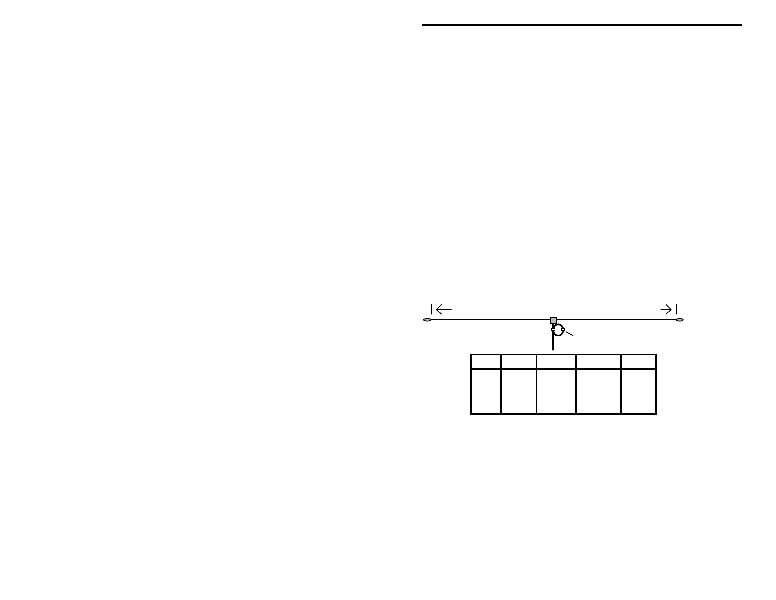
Experience has shown that a full-sized 1/2 wave dipole or sloper installed as
high as possible is hard to beat. The fo llowing chart suggests dip ole wire lengths
for various CW sub-bands. These dimensions are sensitive to ground conditions
and near-by objects, so you may need to prune the length slightly to obtain
minimum VSWR at your location. Information is also provided for adding a
very low cost "choke" balun to your installation. A balun helps eliminate
unwanted feedline radiation on transmit and noise pick-up on receive. Heavyweight or premium cables are not required for QRP stations, and inexpensive
RG58 is sufficient to do the job. The lighter your coax, the higher you can pull
the center of your antenna.
Length
#14 stranded-copper wire
Balun
Band MHz. Length Per-side
80 3.6 130' 0" 65' 0"
40 7.1 66' 0" 33' 0"
30 10.1
20 14.05
Balun consists of RG58 coiled 10" in diameter and held with tape or plastic tie-wraps
46' 4" 23' 2"
33' 2' 16' 7"
Balun
20'
14'
10'
8'
For additional antenna information on a wide variety of HF antennas, consult the
ARRL Antenna Handbook, a publication of the American Radio Relay League
in Newington, Connecticut.
QRP Operating Tips:
Most QRP DXers agre e the "hunt-and -pounce" method
works best. Rather than spending a lot of time calling CQ, look for other
stations calling CQ and answer them. Also, call stations that have just completed
a QSO and signed. When you do call CQ, you can usually expect more replies
around the QRP calling frequency where operators anticipate weaker signals.
Finally, never hesitate to call weak stations--they may also be operating QRP or
31
Page 34

VEC-1320K/1330K/1340K/1380K Owner's Manual
may simply have poor transmitting antennas! You'll soon discover world-wide
QRP contac ts a re rout ine. A gr owing legion o f CW o per ato rs have QRP-D XCC
certificates hanging on the wall to prove it!
IN CASE OF DIFFICULTY
Your VEC QRP-CW Transc eiver has be en thoroughl y field-tested and is known
to be r eliable and " forgiving" of const ruction e rrors. If you have diffi culty with
your unit, the cause may be something as simple as a broken cable or a defective
power source. In most cases, you will be able to find the problem with some
organized troubleshooting. Begin your search with this checklist of symptoms
and remedies:
Does not power up:
cable. Also, check supply polarity, direction of D3, and inspect the fuse trace
near J1.
Does not key:
construction errors. Make sure Y1 is installed correctly. Listen for off-air
signals in receive mode to confirm that Q1 is oscillating.
Weak Signal, no measurable output:
check polarity of D1 and D2. Vcc should be present on case of Q3.
Low Transmitter Output:
and check number of turns on L4.
Severe chirp or motorboating on signal:
Q4. Check D1 and D2 for incorrect polarity or diode failure.
Transmitter remains on when unkeyed:
check Q4 and transmitter component values.
Receiver insensitive:
AM foreign broadcast interference:
station grounding, etc. Turn down R1. Overload by powerful AM shortwave
signals may be unavoidable with unidyne detectors under certain extremelystrong signal conditions.
Audio Oscillation:
Also, reduce receiver gain (R1) on extremely strong signals.
Check your key and plug. Also, check circuitry around Q4 for
Check the condition of your power source and connecting
Check for construction errors. Also,
Check transmitter capacitor values against parts list,
Check component values around Q1,
Check polarity of D1,D2. Also,
Check setting of R1, t uni ng of C1, antenna connections.
Check resonant frequency of antenna,
Check component values and capacitor polarity around U2.
VXO cap fails to shift frequency:
Blown Crowbar Fuse:
direct short circuit from Vcc to ground on the pc board. The etched copper fuse
32
Usually caused by reverse power connection or by a
Check L1, C16.
Page 35
VEC-1320K/1330K/1340K/1380K Owner's Manual
may be replace by a small 1-A pigtail fuse or by a short length of #32 enameled
wire. Your kit will not power up until this is replaced.
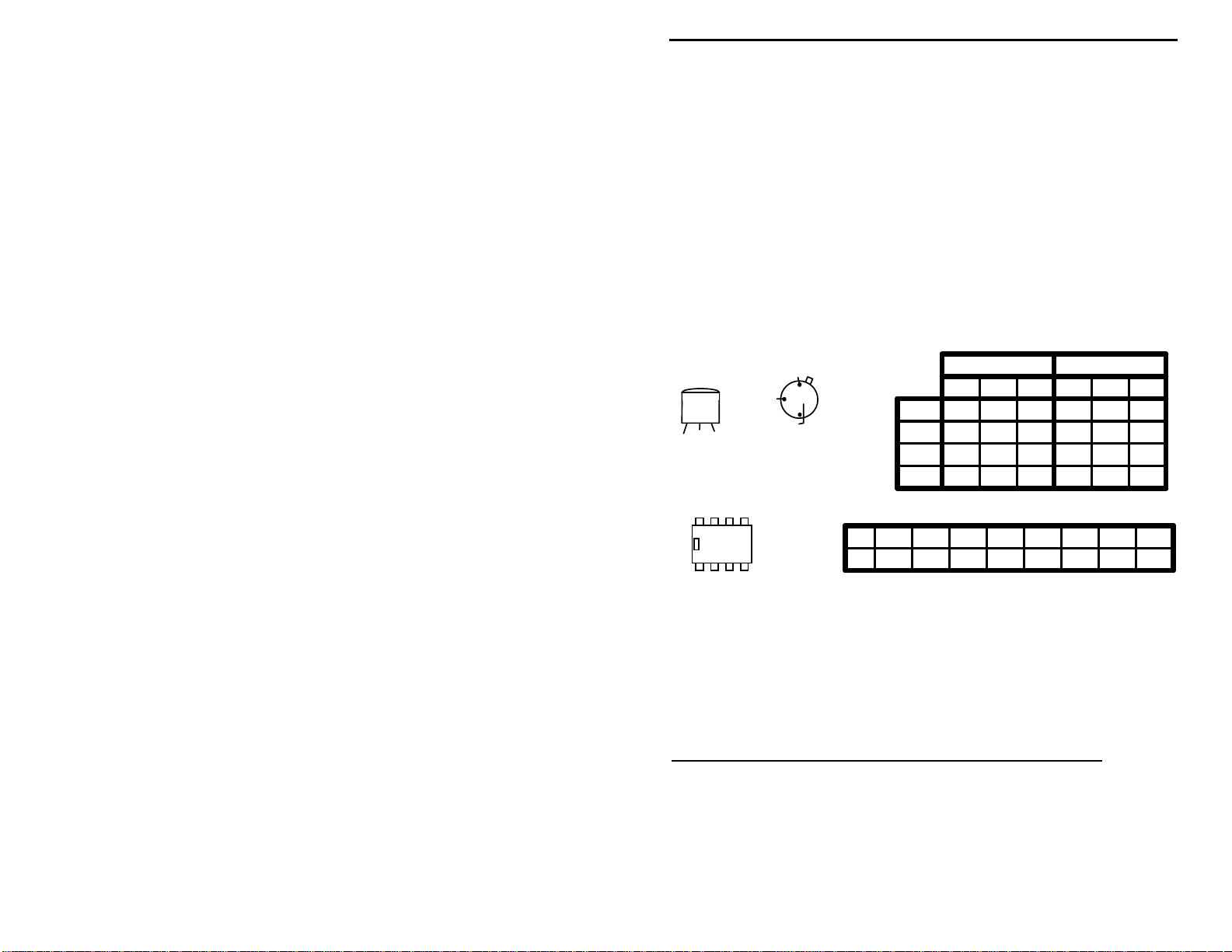
Voltage Analysis:
Voltage analysis is a great way to pinpoint circuit problems.
To do this, you'll need a voltmeter or DVM. Clip the black lead (-) to ground
and use the red (+) probe to check the DC voltage at each IC or transistor lead.
Before making key-down transmitter readings, desolder and remove Y1 from the
pc board to prevent the transmitter from generating RF while you're attempting
to make DC voltage measurements. Receiver IC readings are made with the unit
in receive mode. Compare your readings against the chart below. They should
agree within 10-15%. If you observe one or more "bad" readings, this may
mean the device you're checking is blown--or that an incorrectly-installed part is
lurking near-by. Try using the schematic diagram to trace out the exact cause of
the problem.
2N3904-Q1
PN2222-Q2
2N3906-Q4
E B C
Front View
Important Note: Unit must not
generate RF during these checks!
8 7 6 5
U1/U2
1 2 3 4
(Emitter is grounded)
E
B
(Collector is on Case)
Top View
2N3053
C
NE602
LM386
Q3
U1
U2
Q1
Q2
Q3
Q4
12345678Pin
1.4 1.4 0 4.7 4.7 5.9 6.05.2
1.4 .02 .01 0 6.7 13.8 7.0 1.4
VOLTAGE CHART
Standby Key-Down
EBCEBC
0 0 0 5.7 6.3 12.6
0
0 13.8
0 0 13.8 0 0 13.8
13.8 13.2 0 13.8 13.0 13.6
0
.7 7.7
If these checks fail to uncover the problem, repeat the "QC" check one more
time. Service records show that, for most malfunctioning kits, outright
component failure is relatively rare. In most cases, the culprit is a misplaced
part, reverse-polarized capacitor or diode, improperly installed transistor, or a
faulty solder connection! If, despite your best effort, you cannot solve a problem
with your radio, kit repair services are available through Vectronics. See the
warranty on the inside front cover for complete instructions.
THEORY OF OPERATION AND SPECIFICATIONS
The transceiver consists of a simple direct-conversion receiver and a three-stage
CW transmitter. Operating frequency is controlled by VXO (variable crystal
oscillator) Q1. Q1 is keyed on and off during transmit mode by dc-switch Q4.
During receive, it operates at reduced voltage which reduces mixer drive and
33
Page 36

VEC-1320K/1330K/1340K/1380K Owner's Manual
forces a frequency shift for CW offset. D1 and D2 isolate Q1's +T and +R
voltage sources.
The RF input and AF output ports of unidyne detector U1 are configured for
differential-mode to enhance common-mode noise rejection and provided
highest gain. RF gain control (R1) and high-Q preselector (T1/C1/C2) preceed
the mixer input. AF output response is rolled off at high frequencies by C6.
U2 is a two-stage AF-power op-amp configured in high-gain mode by feedback
capacitor C7. Loop-gain is further increased in the 600 Hz range by a second
frequency-selective feedback network (R3/C11/C12). MUS (minimum usable
sensitivity) exceeds 1 uV, while high-frequency AF products are rolled off for
QRM reduction. U2 provides over 100-mW AF drive into 8 ohms, which is
more than adequate to drive low-Z headphones and 8-ohm extension-type
speakers.
In transmit mode, dc-switch Q4 provides shaped keying of VXO Q1 and
supplies turn-on bias to driver Q2. PA Q3 operates in class-C and draws current
only when RF drive is present. Broadband matching techniques are used to
eliminate critical tune-up steps for the builder. A pi-section low-pass filter
provides impedance matching and harmonic suppression between Q3 and the 50ohm antenna port. CW output normally exceeds 1 Watt (+30 dBm) with -35
dBc or better harmonic suppression.
For simplicity, transceiver T/R functions are handled by a DPDT switch. A
second switch applies power to the radio, and crowbar diode D3 protects
transceiver circuitry against accidental reverse-polarity power connection. If
"on-board" CW sidetone generation is required, a small powered peizo-sounder
may be connected to key-switch Q4 through current-limiting resisto r R10.
Typical Specifications:
RF power output: 1.2 watts @ 14 MHz (may be greater at lower frequencies)
Suppression: -35 dBc or better
VXO tuning range: 9 kHz typical at 14 MHz (will be less at lower frequencies)
VXO T/R offset: 300-500 Hz @ 14 MHz (will be less at lower frequencies)
Receiver sensitivity: .3 uV minimum usable signal on all bands
Receiver current: 25 mA at 13.8 Volts DC
Transmit current: 250-350 mA at 13.8 Volts DC
SCHEMATIC
34
Page 37

Page 38

VEC-1320K/1330K/1340K/1380K Owner's Manual
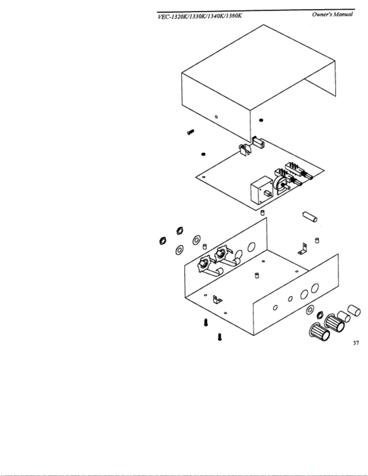
ENCLOSURE
To install your transceiver in the VEC-1300KC matching enclosure follow these
instructions
1.
Find the fron t panel decal and rear p anel decal; separate usin g scissors. Be sure to
2.
Next, install the two L-brackets on the chassis using two of the 3/16" screws. The
3.
Install the four 1/2" mounting screws next. Insert the screws, from the bottom,
4.
Place the four 3/16" round spacers on the mounting screws.
5.
Now insert the PC board. This must be done by:
6.
Use the four hex nuts to secure the PC board. Be certain all appropriate components
7.
Find the knobs and switch caps. Align the red switch cap with SW1 and push it on.
8.
Locate the two 1/4” phone jacks, two silver washers, and two large nuts. Place a
9.
Install the top now. Use the two remaining 3/16" screws for securing the top to the
10.
Finally, place the four rubber feet on the bottom of the enclosure at the corners.
(read all instructions before beginning ... take your time)
leave excess decal material around the edges. Put the rear panel decal on first. This
is done by:
using a piece of cloth and alcohol.
adhesive.
Gently rub the alignment circles with your finger--if the circles are centered in the
enclosure holes (also check the corner alignment marks) secure the decal by rubbing
and removing all air bubbles.
decal accordingly, th en secure.
away the unused edges (cut from the adhesive side) and cut out the component holes
(cut from the description side).
longer side of the L-bracket must be connected to the chassis using the two holes
centered on each edge o f the enclosure. Refer to the d iagram on the next page for
location and orientation.
through the four holes relatively close to each corner of the chassis.
from R1.
respective holes.
screws align with the mounting holes in the PC board before pushing.
are centered with the enclosure holes before tightening. Put the washers and nuts-removed from R1--back on and tighten.
Repeat for SW2 with the black switch cap. If the caps are difficult to push on, then
rotate them 90° and try again. Now put the knobs on R1 and C16. You may need to
loosen the set screw. Align appropriately then tighten the set screws.
washer on the speaker jack and insert into the rear mounting hole labeled SPKR.
Put one of the nuts on the jack and tighten. Repeat this process for the key jack and
insert into the mounting hole labeled KEY.
L-brackets. Make sure the L-brackets are aligned properly.
a.)
Remove all debris and oil from the chassis. This should be done
b.)
Remove the crack and peel to exp ose the
c.)
Place the decal on the rear panel without securing it completely.
e.)
If the alignment circles are n ot cent ered, adj ust th e
f.)
Use a penknife, or small Exacto
g.)
Repeat this procedure for the front panel.
a.)
Remove the nuts and washers
b.)
Insert the front of the P C board at an angl e so the controls enter their
c.)
Push down on the rear of the board. Make sure the mounting
:
TM
knife, to cut
d.)
35
Page 39
 Loading...