

Page 1

VEC-1292K Owner’s Manual Stereo Transmitter Kit
INTRODUCTION
General Information: This nifty little transmitter will send your favorite tunes
with you--throughout the house o r o ut i n the yard . W i sh your W a lkman
CD player? No problem! Connect the VEC-1292K to your stereo's CD player
and broadcast it to where you are. Can't pick up that distant FM station down in
your basement shop? Simple! Connect the VEC-1292K to your stereo's FM
tuner (the one with the big antenna), and rebroadcast the program on a clear
channel. Thanks to the transmitter's specialized IC, you get true stereo with
outstanding signal quality--just like FM radio stations generate from their
studios. The uses are endless!
Circuitry: The VEC-1292K uses a sophisticated IC containing all of the
circuitry needed for a miniature FM broadcast station. The audio stages,
multiplex-stereo modulator, and transmitter RF section are all there--on one
chip! The transmitter's sub-carrier oscillator is crystal controlled for rock-steady
stereo lock-up on receivers. A channel balance control ensures perfect
symmetry. It's even pre-emphasized for the 75 uS US-broadcast standard. The
IC has everything you need to put a broadcast-quality stereo signal on the air in
your own home. Operat ing fr eq ue ncy is inte r nall y adj ustab l e, and a tuned outp ut
network matches the transmitter to a built-in collapsible antenna.
TM
had a
TOOLS AND SUPPLIES
Construction Area: Kit construction requires a clean, smooth, and well-lighted
area where you can easily organize and handle small parts without losing them.
An inexpensive sheet of white poster board makes an excellent construction
surface, while providing protection for the underlying table or desk. Diffused
overhead lighting is a plus, and a supplemental high-intensity desk lamp is
especially helpful for close-up work. Safety is always important! Use a suitable
high-temperature stand for your soldering iron, and keep the work area free of
clutter.
Universal Kit-building Tools: No special tools are required to complete this
kit beyond common items normally used for bench construction. We
recommend the following:
! Soldering iron (grounded-tip and temperature-controlled preferred)
! High-temperature iron holder with cleaning sponge
! Solder, 60/40 or 37/63 with rosin or "no-clean" flux (.031" dia. is good
size).
! Needle nose pliers or surgical hemostats
1
Page 2

VEC-1292K Owner’s Manual Stereo Transmitter Kit
! Diagonal cutters or "nippy cutters"
! Solder sucker (squeeze or vacuum pump type), or desoldering braid
! Bright desk lamp
! Magnifying glass
! Insulated tuning tool set
BEFORE YOU START BUILDING
Experience shows there are four common mistakes builders make. Avoid these,
and your kit will probably work on the first try! Here's what they are:
1. Installing the Wrong Part: It always pays to double-check each step. A 1K
and a 10K resistor may look almost the same, but they may act very
differently in an electronic circuit! Same for capacitors--a device marked
102 (or .001 uF) may have very different operating characteristics from one
marked 103 (or .01uF).
2. Installing Parts Backwards: Always check the polarity of electrolytic
capacitors to make sure the positive (+) lead goes in the (+) hole on the
circuit board. ICs have a notch or dot at one end indicating the correct
direction of insertion. Always double-check--especially before applying
power to the circuit!
3. Faulty Solder Connections: Inspect for cold-solder joints and solder
bridges. Cold solder joints happen when you don't fully heat the connection-or when metallic corrosion and oxide contaminate a component lead or pad.
Solder bridges form when a trail of excess solder shorts pads or tracks
together (see solder tips below).
4. Omitting or Misreading a Part: This is easier to d o than you might think!
Always double-check to make sure you completed each step in an assembly
sequence.
Soldering Tips: Cleanliness and good heat distribution are the two secrets of
professional soldering. Before you install and solder each part, inspect leads or
pins for oxidation. If the metal surface is dull, sand with fine emery paper until
shiny. Allow the tip of your iron to contact both the lead and pad for about one
second (count "one-thousand-one") before feeding solder to the connection.
Surfaces must become hot enough for solder to flow smoothly. Feed solder to
the opposite side of the lead from your iron tip--solder will wick around the lead
toward the tip, wetting all exposed surfaces. Apply solder sparingly, and do not
touch solder directly to the hot iron tip to promote rapid melting. Keep a damp
sponge handy to wipe your so ldering tip on. This removes excess solde r, and
2
Page 3

VEC-1292K Owner’s Manual Stereo Transmitter Kit
keeps the tip properly tinned. If the iron is going to sit idling for long periods,
wipe the tip, add some fresh solder, and unplug the iron.
Desoldering Tips: If you make a mistake and need to remove a part, follow
these instructions carefully! First, grasp the component with hemostats, needlenose pliers, or your fingers. Heat the pad beneath the lead you intend to extract,
and pull gently. The lead should come out. Repeat for the other lead. Solder
may fill in behind the lead as you extract it--especially if you are working on a
double-sided b o ar d with plat e-thr o ugh hol es. Sho uld this ha pp e n, tr y heat ing the
pad again and inserting a common pin into the hole. Solder won't stick to the
pin's chromium plating. When the pad cools, remove the pin and insert the
correct component. For ICs or multiple-pin parts, use desoldering braid to
remove excess solder before attempting to extract the part. Alternatively, a lowcost vacuum-bulb or spring-loaded solder sucker may be used. Parts damaged or
severely overheated during extraction should be replaced rather than reinstalled.
Work Habits: Kit construction requires the ability to follow detailed
instructions and, in many cases, to perform new and unfamiliar tasks. To avoid
making needless mistakes, work for short periods when you're fresh and alert.
Recreational construction project are more informative and more fun when you
take your time. Enjoy!
Sorting and Reading Resistors: The electrical value of resistors is indicated by
a color code (shown below). You don't have to memorize this code to work with
resistors, but you do need to understand how it works:
Resistor Color Code
1st Digit
2nd Digit
Multiplier
Tolerence
(gold or silver)
Black = 0 (tens)
Brown = 1 (hundreds)
Red = 2 (K)
Orange = 3 (10K)
Yellow = 4 (100K)
Green = 5 (1Meg)
Blue = 6
Violet = 7
Gray = 8
White = 9
Silver = 10%
Gold = 5%
When you look at a resistor, check its multiplier code first. Any resistor with a
black multiplier band falls between 10 and 99 ohms in value. Brown designates
a value between 100 and 999 ohms. Red indicates a value from 1000 to 9999
ohms, which is also expressed as 1.0K to 9.9K. An orange multiplier band
designates 10K to 99K, etc. To inventory resistors, first separate them into
groups by multiplier band (make a pile of 10s, 100s, 1Ks, 10Ks, etc.). Next, sort
each group by specific value (1K, 2.2K, 4.7K, etc). This procedure makes the
inventory easier, and also makes locating specific parts more convenient later on
during construction. Some builders find it especially helpful to arrange resistors
in ascending order along a strip of double-sided tape.
3
Page 4
VEC-1292K Owner’s Manual Stereo Transmitter Kit
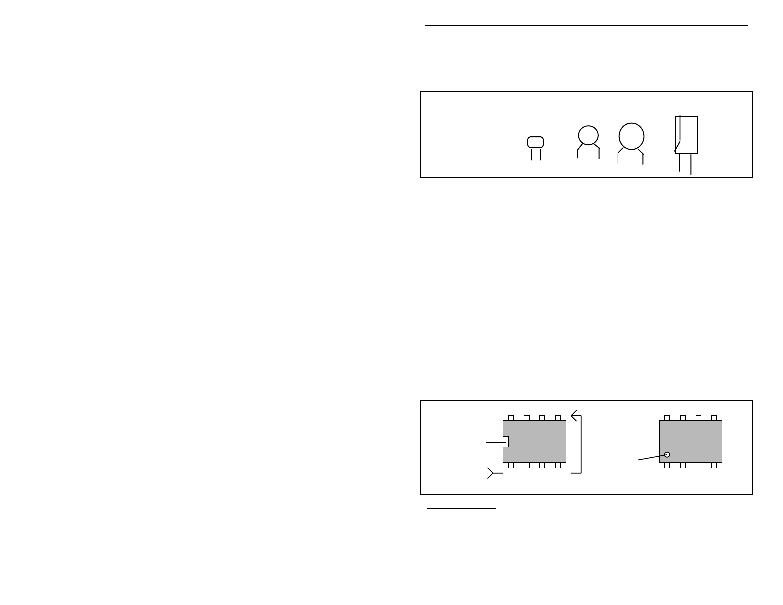
Reading Capacitors: Unlike resistors, capacitors no longer use a color code for
value identification. Instead, the value, or a 3-number code, is printed on the
body.
Value Code
10 pF = 100
100 pF = 101
1000 pF = 102
.001 uF = 102*
.01 uF = 103
.1 uF = 104
Multilayer
(270 pF)
271
Ceramic Discs
(.001 uF) (.1 uF)
102
104
Electrolytic
1 uF
|
1uF
|
35V
+
-
As with resistors, it's helpful to sort capacitors by type, and then to arrange them
in ascending order of value. Small-value capacitors are characterized in pF (or
pico-Farads), while larger values are labeled in uF (or micro-Farads). The
transition from pF to uF occurs at 1000 pF (or .001 uF)*. Today, most
monolithic and disc-ceramic capacitors are marked with a three-number code.
The first two digits indicate a numerical value, while the last digit indicates a
multiplier (same as resistors).
Electrolytic capacitors are always marked in uF. Electrolytics are polarized
devices and must be oriented correctly during installation. If you become
confused by markings on the case, remember the uncut negative lead is slightly
shorter than the positive lead.
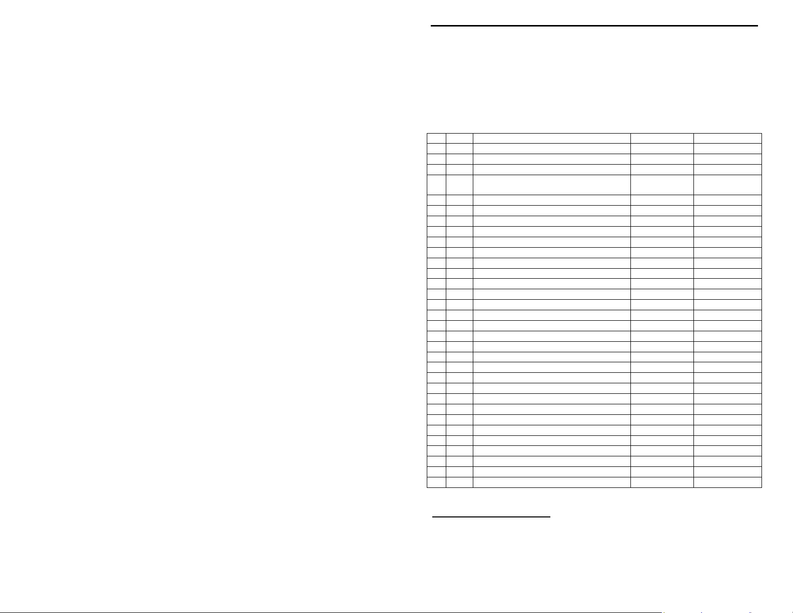
Integrated Circuits: Proper IC positioning is indicated by a dot or square
marking located on one end of the device. A corresponding mark will be silkscreened on the PC board and printed on the kit's parts-placement diagram. To
identify specific IC pin numbers for testing purposes, see the diagram below.
Pin numbers always begin at "1" at the keyed end of the case and progress along
the device, as shown:
8 7 6 5
Installation
Key
1 2 3 4
Pin Numbers
Installation
Key
PARTS LIST
Your kit should contain all of the parts listed below. Please identify and
inventory each item on the checklist before you start building. If any parts are
missing or damaged, refer to the manual's warranty section for replacement
4
Page 5
VEC-1292K Owner’s Manual Stereo Transmitter Kit
instructions. If you can't positively identify an unfamiliar item on the basis of the
information given, set it aside until all other items are checked off. You may
then be able to identify it by process of elimination. Finally, your kit will go
together more smoothly if parts are organized by type and arranged by value
ahead of time. Use this inventory as an opportunity to sort and arrange parts so
you can identify and find them quickly.
"
Qty Part Description Designation VEC P/N
1 470 ohm resistor ( yellow-violet-brown) R8 100-2470
!
1 4.7K ohm resistor (yellow-violet-red) R6 100-3470
!
2 75K ohm resistor ( violet-green-orange) R4,R5 100-4750
!
1 150K ohm resistor ( brown-green-
!
!
!
!
!
!
!
!
!
!
!
!
!
!
!
!
!
!
!
!
!
!
!
!
!
!
!
!
!
*One of these three values will be selected for use at C18--depending on desired frequency range.
yellow)
2 1K trimpot (102) R2,R3 135-3100
1 100K trimpot (104) R1 135-5100
2 10 pF multilayer capac itor (10 or 100) C13,C14 220-0010
2 15 pF multilayer capac itor (15 or 150) C15,C16 220-0015
1 22 pF multilayer capac itor (22 or 220) C18* 220-0022
1 27 pF multilayer capac itor (27 or 270) C18* 220-0027
1 33 pF multilayer capac itor (33 or 330) C18* 220-0033
1 220 pF multilayer capac itor (221) C17 220-0270
6 .001 uF multilayer capacitor (102) C6-C11 220-1100
2 10 uF electrolytic capacitor C3,C4 270-5100-1
2 22 uF electrolytic capacitor C1,C2 270-5220-1
1 100 uF electrolytic capacitor C5 270-6100-1
1 50 pF trimmer capaci tor C12 280-0050
1 .089 uH variable inductor L3 402-2706S
1 1 uH molded choke L2 401-3100
1 6” piece of magnet wire for L1 874-2422
3 1N4148 diode D1-D3 300-4148
1 BA1404 FM transmitter IC U1 325-1404
1 38 kHz crystal (small cylinder , 2 leads) Y1 405-0038
1 Miniature power switch, DPDT SW1 504-2022
2 RCA jack J1,J2 600-0011
1 18 pin socket for U1 625-0018
1 9V battery snap 730-3005
1 2” piece of insulated wire 871-24xx-0300
1 Telescoping antenna 758-1120
1 12mm metric scr ew 675-0012
1 Metric nut 706-3560
1 VEC-1292 printed circuit board 862-VEC1292
R7 100-5150
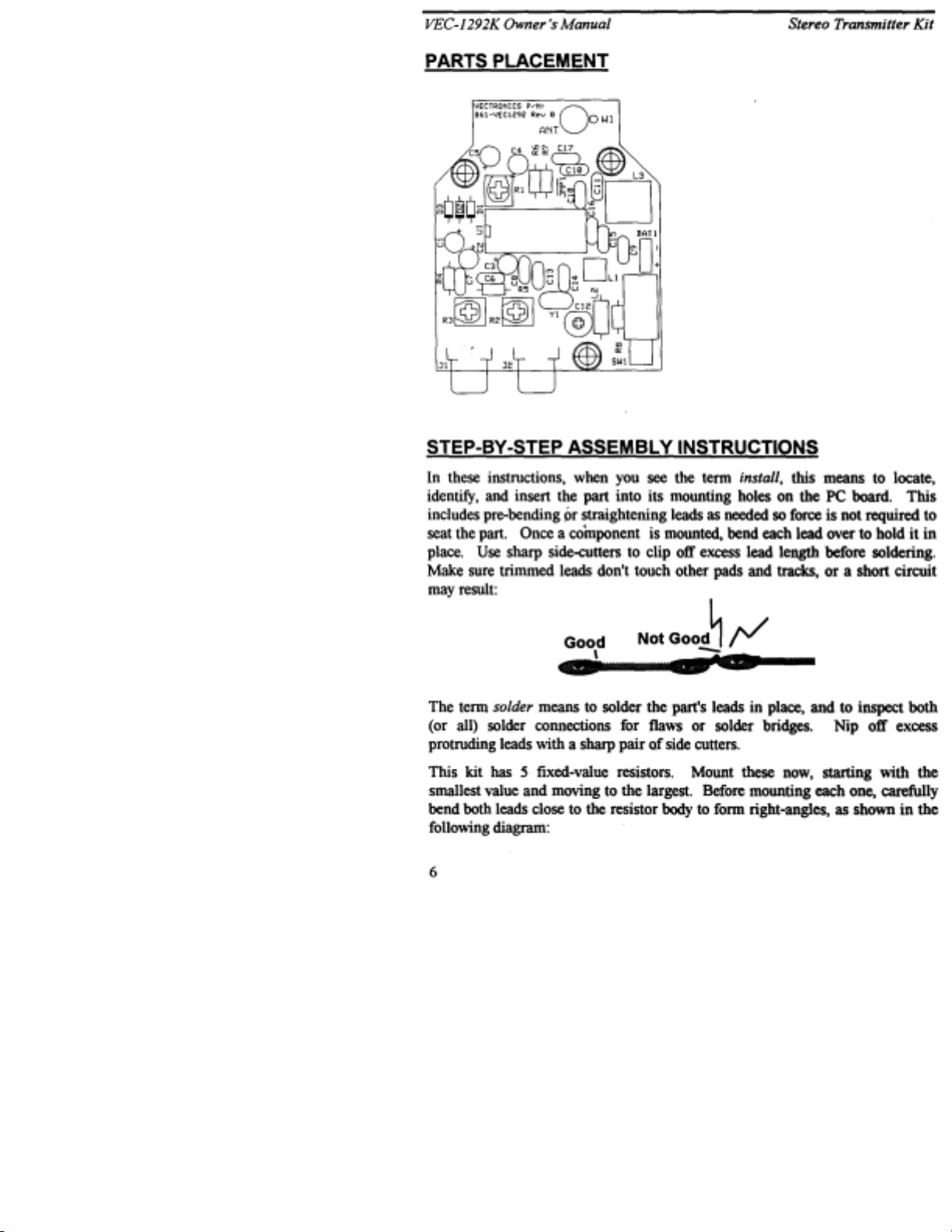
PARTS PLACEMENT
5
Page 6
Page 7
VEC-1292K Owner’s Manual Stereo Transmitter Kit
! ! 1. Find a 470 ohm resistor (yellow-violet-brown). Install at R8 and
solder.
! ! 2. Find a 4.7K ohm resistor (yellow-violet-red). Install at R6 and solder.
Locate the two 75K ohm resistors (violet-green-orange).
! ! 3. Install a 75K at R4 and solder.
! ! 4. Install a 75K at R5 and solder.
! ! 5. Find the 150K ohm resistor (brown-green-yellow). Install at R7.
Next, install the kit's 12 multilayer capacitors. Avoid using force or excessive
heat when installing these. If the spacing isn't right, pre-form leads to the correct
spacing before inserting into the PC board.
Incorrect
Locate two (2) 10 pF multilayer capacitors (marked 10 or 100).
! ! 6. Install a 10 pF at C13.
! ! 7. Install a 10 pF at C14.
Locate two (2) 15 pF multilayer capacitors (15 or 150).
! ! 8. Install a 15 pF at C15.
! ! 9. Install a 15 pF at C16.
The next capacitor determines the frequency-tuning range of your FM
transmitter. For the low end of the band, or 88-94 MHz, find the 33 pF capacitor
(33 or 330). For the middle portion of the band, or 95-102 MHz, find the 27 pF
capacitor (27 or 270). For 102 MHz and up, use the 22 pF capacitor (22 or
220).
! ! 10. Install the capacitor you've selected at C18 and solder.
! ! 11. Find a 220 pF multilayer capacitor (221). Install at C17 and solder.
Locate six (6) .001 uF multilayer capacitors (102).
! ! 12. Install a .001 uF at C6 and solder.
! ! 13. Install a .001 uF at C7 and solder.
Ooops!
Correct
! ! 14. Install a .001 uF at C8 and solder.
7
Page 8

VEC-1292K Owner’s Manual Stereo Transmitter Kit
! ! 15. Install a .001 uF at C9 and solder.
! ! 16. Install a .001 uF at C10 and solder.
! ! 17. Install a .001 uF at C11 and solder.
The last 5 fixed-value capacitors in your kit are electrolytic. Electrolytic caps
are polarized and must be installed the correct way in order to work. Each
capacitor's plus (+) mounting hole is marked on both the circuit board and parts
placement diagram. If the markings on the capacitor body are unclear, the plus
(+) lead is always the longer of the two.
+
Plus Lead
Locate the two (2) 10 uF electrolytic capacitors.
! ! 18. Install a 10 uF at C3 and solder.
! ! 19. Install a 10 uF at C4 and solder.
Locate the two (2) 22 uF electrolytic capacitors.
! ! 20. Install a 22 uF at C1 and solder.
! ! 21. Install a 22 uF at C2 and solder.
! ! 22. Find the 100 uF electrolytic capacitor. Install at C5 and solder.
This completes fixed capacitor installation. Before moving on, check each
electrolytic for correct polarity.
Locate the three (3) 1N4148 diodes (glass body). Like electrolytics, diodes are
polarized devices that must be installed correctly. Always look for the banded
end when installing.
! ! 23. Install a 1N4148 at D1 and solder.
! ! 24. Install a 1N4148 at D2 and solder.
8
Page 9
VEC-1292K Owner’s Manual Stereo Transmitter Kit
! ! 25. Install a 1N4148 at D3 and solder.
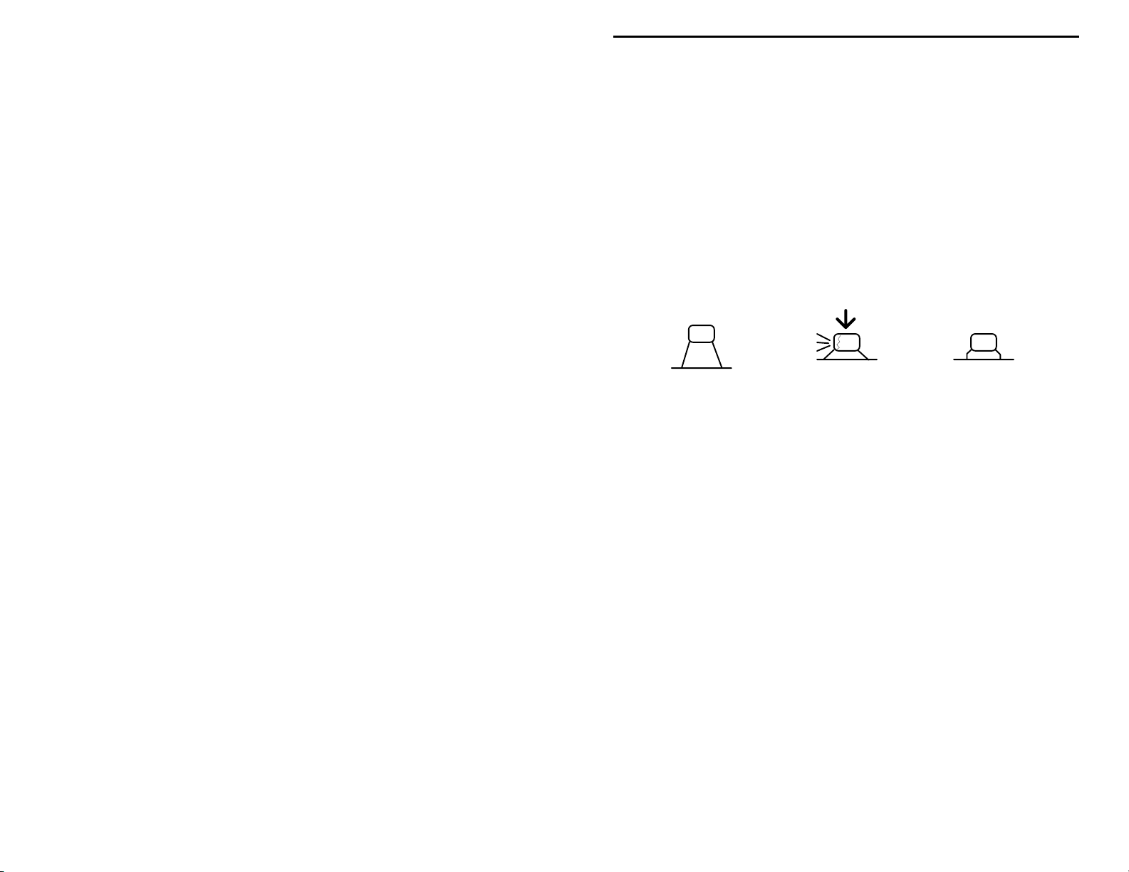
There are three small trimpots in your kit. Find the two (2) 1K trimpots (marked
102).
When installing these, make sure they remain seated firmly against the board
during solder ing.
! ! 26. Install a 1K pot (102) R2 and solder.
! ! 27. Install a 1K pot (102) R3 and solder.
! ! 28. Find the remaining 100K trimpot (marked 104). Install at R1 and
solder.
! ! 29. Find the 50 pF trimcap (orange, screwdriver adjust). Install at C12
with the flat side toward L1 and solder.
Trimcap
Install with the
"round to ground"
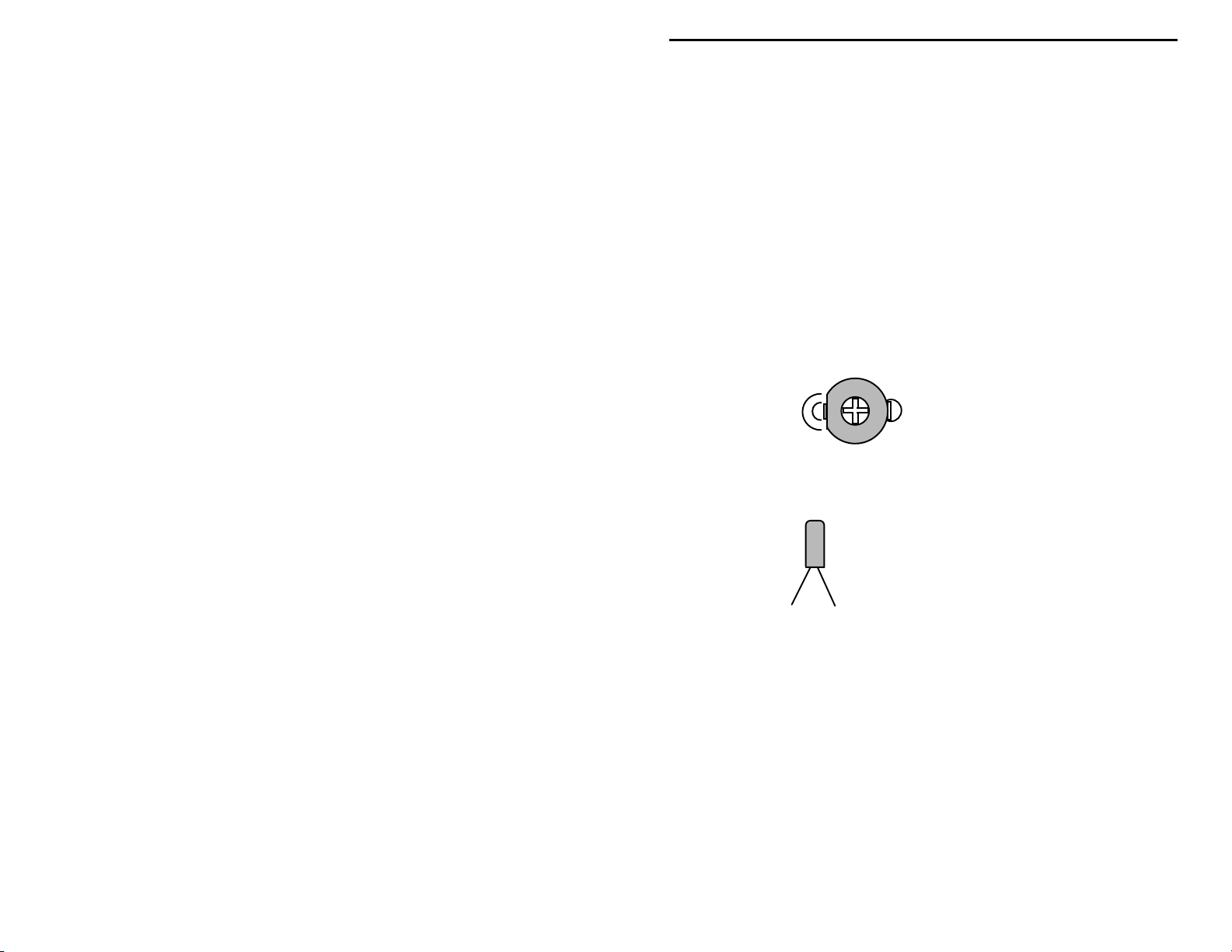
Locate the 38 kHz crystal. This is a small metal tube-shaped package with two
leads protruding from one end.
38 kHz digital watch crystal
! ! 30. Install the 38 kHz crystal at Y1.
Locate the .089 uH slug-tuned coil (red plastic coil form, metal shield can).
Before installing, make sure the coil's two pins and shield-can tabs are straight.
! ! 31. Position the .089 uH coil over the silkscreen legend for L3 and insert
carefully. Bend the two shield-can tabs over and solder in place.
Solder the two wire pins in place.
! ! 32. Find the 1 uH molded choke (brown-black-gold-silver). Install at L2
and solder.
The transmitter's output coil, L1, is a small 5-turn air-wound inductor. Use a 10-
32 screw shaft to make this coil. Ensure there are five complete turns on the
coil. After forming the coil, position as shown in the following:
9
Page 10
VEC-1292K Owner’s Manual Stereo Transmitter Kit
L1
Note:
! ! 33. Install the 5-turn coil at L1 and solder.
L1 requires the addition of a center tap. If your coil has enamel insulation,
locate the center turn and scrape a patch of insulation off with a hobby knife to
expose the copper beneath. If the coil has tin plating, disregard this instruction
and solder directly to the plating.
! ! 34. Get the 2" length of insulated wire and strip 1/4" of insulation from
! ! 35. Tack-solder one end of the insulated wire to the middle turn of L1.
! ! 36. Place the other end of the insulated into W1 and solder.
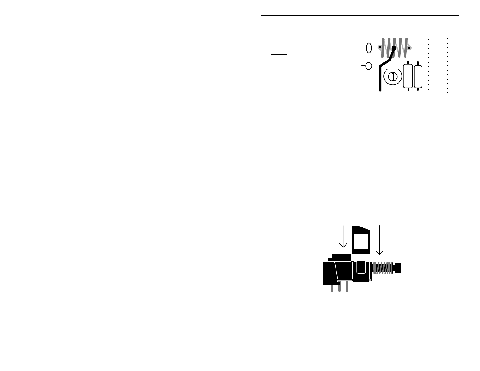
Your kit co ntains a miniat ure DPDT switch. Some versions r equire install ation
of a plastic clip-on support at the front of the switch body. This piece relieves
stress on the pins and ensures level seating. If your parts kit contains this piece,
install as shown:
Separate the turns
evenly so the coil
fits between the
two mounting holes.
both ends (if necessary).
Y1
C12
Antenna Lead
L2
SW1
R8
Once the switch is prepared for installation:
! ! 37. Install the DPDT mini power switch at SW1
The Stereo Transmitter ICs in your kit will be installed using a IC socket. Like
the IC itself, the socket is keyed at one end to indicate proper positioning.
10
Page 11

VEC-1292K Owner’s Manual Stereo Transmitter Kit
During installation, orient the socket so the notch corresponds to the key on the
PC layout.
Key
When installing sockets, make sure all pins enter the mounting holes and appear
on the opposite side of the PC board (it's easy to fold one or more under the
socket). Also, when soldering, make sure the socket remains flat against the
board surface.
! ! 38. Find a 18 pin IC socket. Orient to U1, install, and solder all pins.
Next, align the BA-1404 IC with the socket, matching its key with the socket
key. When you install, press in slowly--making sure all pins go into the socket
holes and none fold over unde r the device.
Locate the 9-V battery snap clip, and note the red+ lead and black- lead.
! ! 39. Install the red lead at (+) on the PC board and solder.
! ! 40. Install the black lead at (-) on the PC board and solder.
Locate the two (2) RCA jacks. When installing, make sure all tabs are firmly
seated in place and the jack is level prior to soldering.
! ! 41. Install a RCA jack at J1.
! ! 42. Install a RCA jack at J2.
! ! 43 . Locate the 12mm meter screw and nut. Place the screw through the
ant hole (from the solder side of the PCB) and tighten with the nut.
Key
! ! 44. Install the antenna by threading it onto the screw.
This concludes wiring of your VEC-1292 FM Stereo Transmitter Kit. Before
moving on to the next section, perform a thorough QC (quality control)
inspection. This will uncover any assembly errors that might prevent it from
working properly--or that could damage sensitive parts when you apply power.
Follow this procedure:
1. Compare parts locations with the parts-placement diagram. Was each part
installed where it is supposed to be? Was the correct value used? Start at
one side of the board and work your way across in an organized pattern.
2. Inspect the solder side of the board for cold-solder joints and solder bridges
between tracks or pads. Use a magnifying glass to obtain a clear view of the
11
Page 12

VEC-1292K Owner’s Manual Stereo Transmitter Kit
track area. If you suspect a solder bridge, hold the board in front of a bright
light for a better view. All joints should be smooth and shiny, indicating
good solder wetting and flow. Resolder any beaded or dull-appearing
connections. Also, check the front-panel jacks, switches, and connectors for
defective solder connections.
3. Finally, check electrolytic capacitors and diodes for correct polarity. Does
the plus (+) polarity symbol on the part agree with the pictorial and with the
pattern on the PC board? Is the banded end of each diode positioned
correctly? Were all ICs installed correctly?
Be sure to correct all errors before moving on.
12
Page 13
VEC-1292K Owner’s Manual Stereo Transmitter Kit
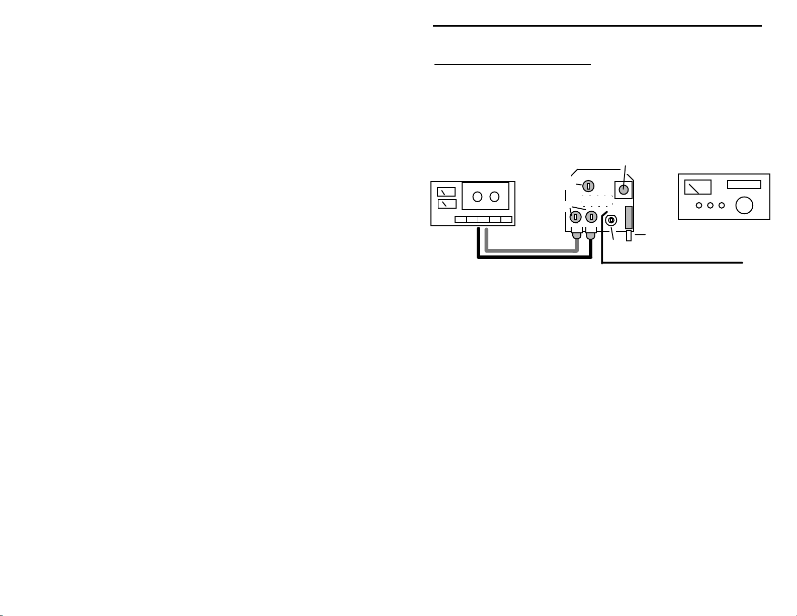
TESTING AND ALIGNMENT
To set up your FM transmitter, you'll need a line-level stereo-audio source such
as a tape cassette or CD player. You'll also need a FM stereo receiver-preferably one with digital frequency readout--to monitor the transmitter's signal.
Your kit has five internal controls that optimize its operation. No sophisticated
test equipment is required to make these adjustments. The set-up for alignment
is shown in the following diagram:
Audio Source
Frequency Adjust
Stereo
Balance
Input Gain
Power On/Off
Transmit
Peak
FM-Stero Receiver
20" Antenna
To begin alignment:
#$Set all three transmitter potentiometers at mid-range (R1, R2, R3).
#$Confirm the power switch is Off (button out).
#$Install a fresh 9V alkaline battery on the battery clip.
#$Turn the power switch on.
#$Turn on the FM receiver and tune to locate the transmitter's un-modulated
signal.
If you are unable to find the signal, your kit may be transmitting "out-of-band".
Using an insulated tuning tool, adjust L3 until the signal is picked up (listen near
the low-frequency end of the FM band if C18 is 33 pF, and near the high end if
it's 22 pF).
If you still can't locate the signal, review assembly instructions and look for an
assembly error. If you do locate it, proceed as follows:
#$Activate your audio source and listen for modulation on the FM receiver.
#$Adjust Gain controls R2, R3 for volume levels slightly below average off-air
signals.
Be sure to make your trimpot settings equal for both channels (we'll adjust the
transmitter for channel balance next). Note that commercial FM stations use
13
Page 14

VEC-1292K Owner’s Manual Stereo Transmitter Kit
sophisticated audio limiters to boost their average modulation level. Your
transmitter doesn't have this feature, so it's best to set the gain trimpots for
modulation that's slightly below commercial broadcast levels to prevent overmodulation. Once a modulation level is set, adjust for channel balance. You
may find it helpful to wear stereo headphones for this particular adjustment:
#$Listen to the signal on your FM receiver. Is the signal undistorted and clear?
#$Look at your FM-receiver's stereo pilot--is it "locked up" to a stereo signal?
#$Switch between mono and stereo--is there audible channel separation?
#$Set the FM receiver's balance control to its center position.
#$Adjust the transmitter's balance (R1) for equal volume from both channels.
If you don't have a good FM stereo monitor receiver or a well-balanced audio
source available, you may simply set the transmitter balance trimpot to its midpoint. In most cases, this will yield satisfactory results.
If you have a specific transmitter operating frequency in mind, a FM receiver
with digital frequency readout will help you set the transmitter's oscillator
accurately (simply tune to that channel). If you merely wish to find a clear
channel, tune around for a good one that falls within the tuning range of the
transmitter's oscillator. Note that the FCC assigns FM channels for 200 kHz
spacing, starting 100 kHz above the band edge. Channel numbers progress from
88.1, 88.3, etc up to 107.9 MHz. You may find it beneficial to comply with this
standard, since some low-cost synthesized FM receivers tune in 200 kHz steps.
Begin the frequency-setting procedure by tuning your FM receiver to the desired
channel.
#$Using an insulated tuning tool, adjust L3 until your transmitter is on
frequency.
If you have a discriminator indicator (or tuning meter) on your stereo receiver,
use this when fine-tuning L3. If this feature isn't available, set L3 for leastdistorted audio--making sure the receiver's stereo pilot illuminates. This
indicates the FM receiver is locked onto the transmitter's stereo sub-carrier.
Note that some frequency drift is normal for simple L/C tuned oscillator circuits,
so you should expect some variation in transmit frequency over time.
To adjust the transmitter's output peaking control, use your FM receiver's signalstrength meter. If the meter deflects full scale during this operation, remove the
receiver's antenna to reduce sensitivity.
#$Using an insulated tuning tool, set C12 for maximum meter deflection.
14
Page 15

VEC-1292K Owner’s Manual Stereo Transmitter Kit
This completes alignment of your transmitter. Note that readjustment of the
transmitter's gain controls R2, R3 may be necessary if you substitute an audio
source with significantly higher or lower output level. Always re-check your
modulation level against a commercial station when connecting to a new audio
source.
Important Warning:
you are solely responsible for its legal use
transmitter of this type to a full-sized outdoor FM band antenna for the
purpose of "neighborhood broadcasting" c onstitutes a clear violation of FCC
Rules under Part 95. It is also a violation of FCC rules to cause willful or
harmful interference to the normal reception of commercial FM broadcast
signals.
modification of this product
Verctronics cannot be held responsible for the misuse or illicit
As the builder and operator of this transmitter circuit,
. Please note that connecting a
.
If you have purchased the matching case for your VEC-1292K, now is a good
time to install it.
15
Page 16

VEC-1292K Owner’s Manual Stereo Transmitter Kit
OPERATING INSTRUCTIONS
Once your VEC-1292K is set up, its operation is relatively simple. A typical setup is illustrated below:
Antenna
Audio
Connections
VEC-1292
Power
CD Player
Power: Press the unit's power switch "in" to activate the transmitter. Press to
the "out" position to turn the transmitter off. Always check the switch before
storing to ensure that the unit wasn't inadvertently left "on".
Audio Connections: Accepts standard RCA type stereo patch cords.
Audio Levels: Accepts industry-standard accessory audio levels (100 mVrms to
1 Vrms).
Antenna: Extend, only as needed, to provide adequate reception. The antenna
need not be extended fully for the unit to operate.
Battery: Use a 9V flat-pack alkaline-type battery. Check periodically for
battery condition.
Frequency: To change opera ting freque ncy or adj ust modulation leve l, refer to
the Testing and Alignment section of this manual for detailed instructions.
Sudden changes in temperature or excessive heating of the case may cause a shift
in the transmitter operating frequency. To avoid excessive frequency drift, avoid
operating in direct sunlight. Also, avoid operation on local in-use FM broadcast
channels, as your transmitter may cause "harmful interference" to normal
reception in violation of FCC rules.
16
Page 17

VEC-1292K Owner’s Manual Stereo Transmitter Kit
IN CASE OF DIFFICULTY
Before seeking outside assistance, check below for a possible solution:
Does not turn on: Check battery condition, snap clip, and power leads. Also,
make sure lead polarity is correct (red to +, black to GND). Make sure power
switch is "on".
Drifts off Frequency: Check battery condition. Also, check to see if the unit is
exposed to direct sunlight--or near heating/cooling source such as a radiator or
air conditioner.
High audio level, distortion: Check gain settings and output rating of audio
source. Transmitter may be over-modulated.
Low audio level: Check gain settings and output rating of audio source.
Transmitter may be under-modulated. Note that "microphone level" signals
aren't sufficiently powerful to modulate the transmitter.
Operation off frequency: Unit may have been bumped or jolted causing
movement to the tuning slug in L3. Readjust.
Weak signal: Check condition and extension of antenna. Re-tune C12 if
needed.
No Stereo: Check your program source--is it in stereo? Also, confirm your
receiver is indicating stereo signal "lock-up". Transmitter (or receiver) may
have drifted off frequency causing the stereo det ector to unlo ck.
If this check fails to uncover the problem, repeat the "QC" check one more time.
Service records show that, for most malfunctioning kits, outright component
failure is relatively rare. In most cases, the culprit is a misplaced part, reversepolarized capacitor, improperly installed IC, or a faulty solder connection. If,
despite your best effort, you cannot solve the problem, kit repair services are
available through Vectronics. See the warranty on the inside front cover for
complete instructions.
17
Page 18

VEC-1292K Owner’s Manual Stereo Transmitter Kit
THEORY OF OPERATION
The BA1404 transmitter IC contains a number of specialized circuits for
generating the on-air FM stereo signal. Independent left and right audio inputs
are pre-emphasized for 75 uS (US standard) and buffered through identical
amplifiers. The L and R signals are then fed into the multiplexer section, along
with 38 kHz LO from crystal-controlled oscillator Y1. Here, the two audio
channels are combined to produce a monaural-compatible L+R signal. Samples
are also subtracted to generate a second L-R difference signal. The difference
signal is superimposed over the LO in a balanced modulator circuit to generate a
38 kHz suppressed-carrier DSB signal. Unmodulated 38 kHz LO is also
sampled through a frequency-divider stage to generate a 19 kHz stereo-pilot
signal.
Carrier
Frequency
L+R Signal
Multiplex Stereo FM Signal
A L/C-tuned VHF-range oscillator generates the transmitter's primary carrier
signal. This stage is user-adjustable to cover the 88-108 MHz band. To
generate a multiplex stereo signal, the IC's FM modulator stage superimposes the
L+R audio signal, the 19 kHz stereo pilot, and the 38 kHz DSB L-R signal onto
the fundamental carrier. This signal is then fed through a buffer/low-level
amplifier connected to the transmitter's RF output network.
19-kHz Pilot
L-R Signal
38-kHz Suppressed
Subcarrier
18
Page 19

Page 20

VEC-1292K Owner’s Manual Stereo Transmitter Kit
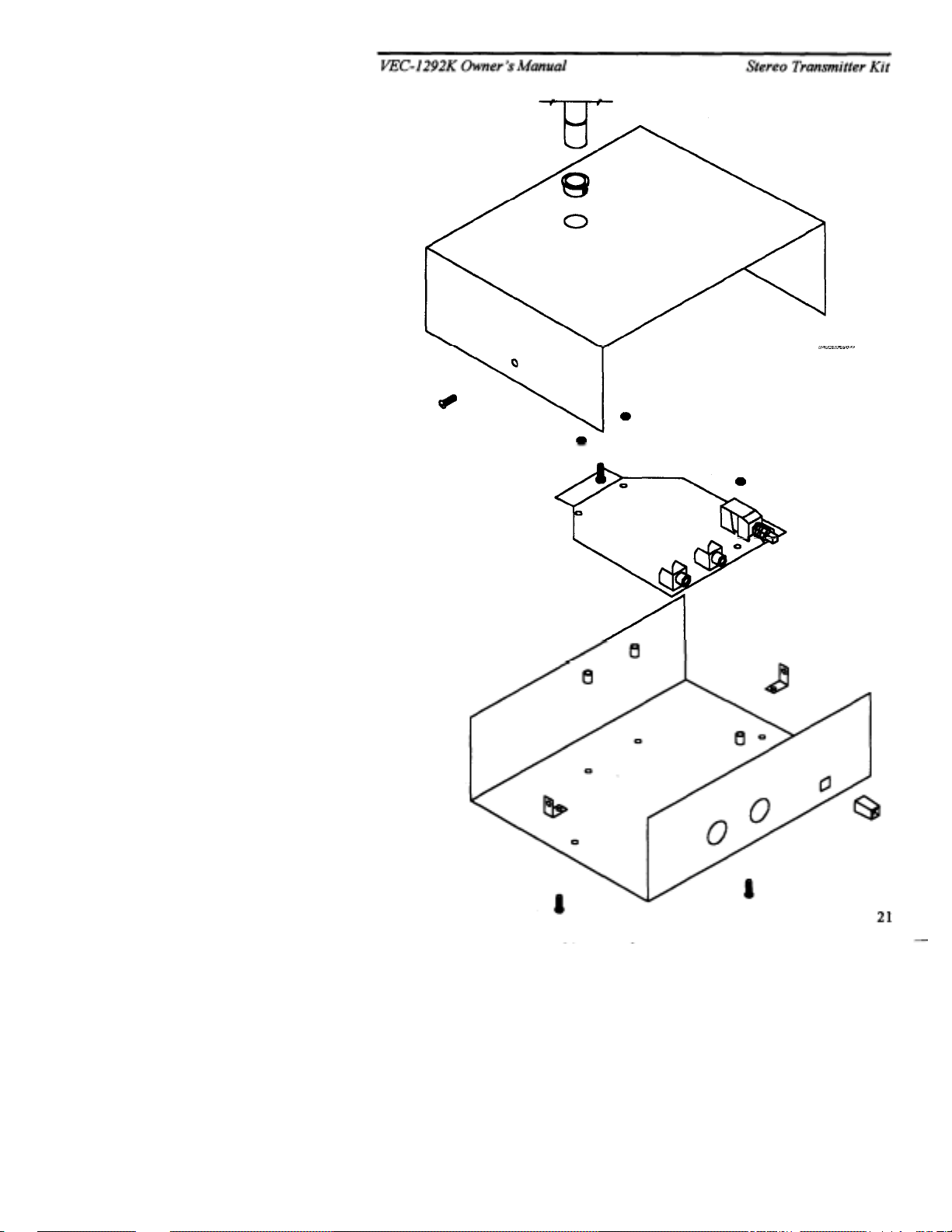
ENCLOSURE
To install your transmitter in the VEC-1292KC matching enclosure follow these
instructions (read all instructions before beginning ... take your time):
1.
Find the fron t panel decal and rear p anel decal; separate usin g scissors. Be sure to
leave excess decal material around the edges. Put the front panel decal on first.
This is done by:
crack and peel to expo se th e adh esive.
securing it completely.
circles are centered in the enclosure ho les (also check the corner align ment marks)
secure the decal by rubbing and removing all air bubbles.
are not centered , adjust the d ecal accordingly then secure.
small Exacto
(cut from the description side).
the corner alignment marks.
2.
Next, install the two L-brackets on the chassis using two of the 3/16" screws. The
longer side of the L-bracket must be connected to the chassis using the two holes
centered on each edge o f the enclosure. Refer to the d iagram on the next page for
location and orientation.
3.
Install the three 1/2" mounting screws next. Insert the screws, from the bottom,
through the three holes in the chassis.
4.
Place the three 3/16" round spacers on the mounting screws.
5.
Now insert the PC board. This must be done by:
at an angle so the cont rols enter th eir respective ho les.
the board. Make sure the mounting screws align with the mounting holes in the PC
board before pushing.
6.
Use the three hex nuts to secure the PC board. Be certain all appropriate
components are centered with the enclosure holes before tightening.
7.
Find the switch cap. Align the switch cap with SW1 and push it on. If it is difficult
to push on, then rotate it 90° and try again.
8.
Locate the piece of double-sided tape. This is to be used for holding the 9-volt
battery clip in place. Locate a place on the underside of the top cover where the
battery will not interfere with any components. Peel off the backing of the tape and
stick it to the chosen location.
9.
The top should be installed next. Use the two remaining 3/16" screws for securing
the top to the L-brackets. Make sure the L-brackets are aligned properly.
10.
Place the small round bushing into the hole on the top of the box. Press the bushing
down until it snaps in. Then slide the antenna through the hole and screw onto the
ANT screw until tight.
11.
Finally, place the four rubber feet on the bottom of the enclosure at the corners.
a.)
Remove all debris and oil from the chassis.
c.)
Place the decal on the front panel without
d.)
Gently rub the alignment circles with your finger--if the
e.)
TM
knife, to cut away the unused edges and cut out the component holes
g.)
Repeat this procedure for the rear panel using
a.)
Insert the front of the PC board
b.)
Push down on the rear of
b.)
Remove the
If the alignment circles
f.)
Use a penknife, or
20
Page 21
 Loading...