

Page 1

IMPORTANT WARRANTY INFORMATIO NI PLE ASE REA D
p
I
Return Policy on Kits When Not Purchased Directly From V ectronics: Before continuing any
further with your VEC kit check with your Dealer about their return policy. If your Dealer
allows returns, your kit must be returned before you begin construction.
Return Policy on Kits When Purchased Directly From Vectronics: Your VEC kit may be
returned to the factory in its pre-assembled condition only. The reason for this stipulation is,
once you begin installing and soldering parts, you essentially take over the role of the device's
manufacturer. From this point on, neither Vectronics nor its dealers can reasonably be held
accountable for the quality or the outcome of your work. Because of this, Vectronics cannot
accept return of any kit-in-progress or completed work as a warranty item for any reason
whatsoever. If you are a new or inexperienced kit builder, we urge you to read the manual
carefully and determine whether or not you're ready to take on the job. If you wish to change
your mind and return your kit, you may-but you must do it before you begin construction,
Vectronics Warrants: Your kit contains each item specified in the parts list.
Missing Parts: If you determine, during your pre-construction inventory, th at any part js
missing, please contact Vectronics and we'll send the missing item to you free of charge.
However, before you contact Vectronics, please look carefully to c onfirm you ha ven't misr ead
the marking on one of the other items provided with t he kit . A lso, make cert ain an altern ative
part hasn't been substituted for the item you're missing. If a specific part is no longer
available, or if Engineering has determined that an alternative comp onent is more suitable,
Defective Parts: Today's electronic parts are physically and electrically resilient, and defective
components are rare. However, if you discover an item during your pre-construction
inventory that's obviously brok en or unserviceable, we'll replace it. Just ret urn the part to
Vectronics at the address below accompanied with an explanation. Upon receipt, we'll test it.
If it's defective and appears unused, well ship you a new one right away at no charge.
Missing or Defective Parts After You Begin Assembly: Parts and materials lost or damaged
after construction begins are not covered under the terms of this warranty. However, most
parts supplied with VEC kits are relatively inexpensive and Vectronics ca n replace them for a
reasonable charge. Simply contact the factory with a com plete description. We 'll process your
order quickly and get you back on track .
Factory Repair After You Begin Assembly: Kits-in progress and completed kits are specifically
excluded from coverage by the Vectronics warranty. However, as a service to customers,
technicians are available
of $18.00
for repair service, your kit must be fully completed , u nm odified, and the printed circuit board
assembled using rosin-core solder. In the event your repair will require more than an hour to
fix (or 536.00, subject to change), our technicians will contact you in advance by telephone
before performing the work. Defective u nit s should be shipped prepaid
When shipping, pack your kit well and include the minimum payment plus shipping and
handling charges (525.00 total). No work can be performed without pre-payment Also,
rovide a valid UPS return address and a day time phone number where you may be reached.
hour rate) plus $7.00 shipping and handling (prices subject to change). To qualify
('/a
Vectronics
300 Industrial Park Road
Starkville, MS 39759
to
evaluate and repair malfunctioning kits for a minimum service fee
to:
Page 2
Page 3
VEC-1290K Instruction Manual AM Radio Transmitter
INTRODUCTION
Own and operate your own low-cost AM broadcast station! You're the disc
jockey or talk show host-play music from your CD player, tape deck or other
audio source. Play vintage radio show cassettes on your favorite antique radios!
The VEC-1290K is easily setup to broadcast a High-Fidelity signal in the AM
broadcast band between 540 and 1710 kHz-find a clear frequency and broadcast
interference free to your neighbors! The transmitter is
either 9-kHz European or 10-kHz American channel spacings! Accepts audio
from standard line -leve l or micro p ho ne-le vel sour ce s. True hi gh-le ve l Cla ss C
modulation delivers good modulation depth and linearity. No FCC license is
required, its perfectly legal under Part 15 of the FCC rules. This Vectronics kit
features a professional quality epoxy PC board, with solder mask and silkscreened parts legend to make assembly a breeze!
Construction Area: Kit construction requires a clean, smooth, and welllighted
area where you can easily organize and handle small parts without losing them.
An inexpensive sheet of white poster board makes an excellent construction
surface and provides protection for the underlying table or desk. Well-diffused
overhead lighting is a plus, and a supplemental high-intensity desk lamp is
especially helpful for close-up work. Safety is always important! Be sure to use
a suitable high-temperature stand for your soldering iron, and keep the work
area free of combustible clutter.
compatible with
fully
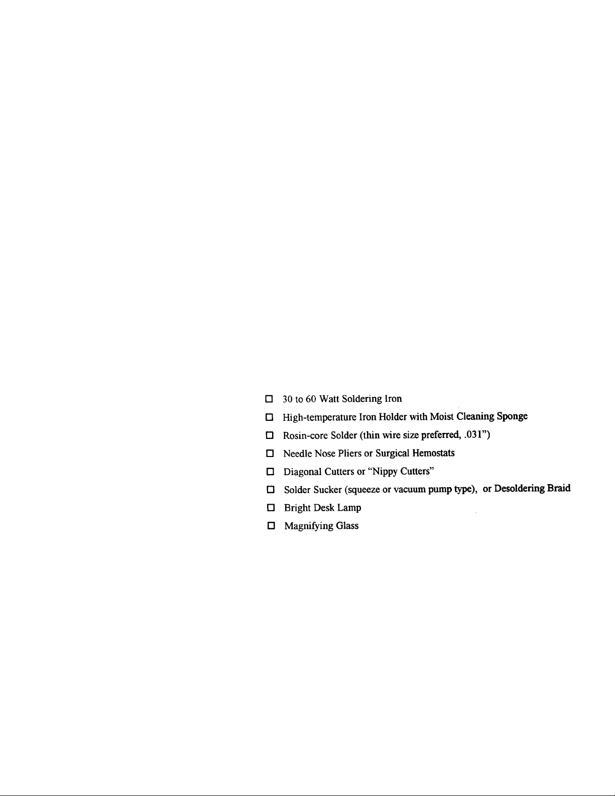
Universal Kit-buil di ng T o o ls: Altho ugh your pa rt icul ar kit ma y req uir e
additional items for completion, virtually all construction projects require a
work area outfitted with the following tools and supplies:
Page 4

BEFORE YOU START BUILDING
y
Experience shows there are four common mistakes builders commonl y make.
Avoid these, and
1. Installing the Wrong Part: It always pays to double-check each step. A 1K
and a IOK resistor may look almost the same, but may act very differently in
an electronic circuit! The same is true for capacitors-a device marked 102 (or
.001 uF) may have very different operating characteristics from one marked
103 (or .01 uF).
2. Installing Parts Backwards: Always check the polarity of electrolytic
capacitors to make sure the positive (+) lead goes in the (+) hole on the
circuit board. Transistors have a flat side or emitter tab to help you identify
the correct mounti ng po sition. IC s have a no tch or dot at one end indi cating
the correct direction of insertion. Diodes have a banded end indicating correct
polarity.
3. Faulty Solder Connec tions: Inspect for cold-solder jo ints and solder
bridges. Cold solder joints occur when you don't fully heat the connection
or when metallic corrosion and oxide contaminate a component lead or
pad. Solder bridges form when a trail of excess solder shorts pads or
tracks together (see Solder Tips below).
4. Omitting or Misreading a Part: This is easier to do than you might think!
Always double-check to make sure you completed each step in an assembly
sequence.
our kit will probably work on the first try!
Soldering Tips: Cleanliness and good heat distribution are the two secrets of
professional soldering. Before you install and solder each part, inspect leads
or pins for oxidation. If the metal surface is dull, sand with fine emery paper
until shiny. Also, clean the oxidation and excess solder from the soldering
iron tip to ensure maximum heat transfer. Allow the tip of your iron to
contact both the lead and pad for about one second (count "one-thousandone") before feeding solder to the connection. Surfaces must become hot
enough for solder to flow smoothly. Feed solder to the opposite side of the
lead from your iron tip. Solder will wick around the lead toward the tip,
Desoldering Tip s: If you make a mistake and need to remove a part, fol low
these instructions carefully! First, grasp the component with hemostats or
needle-nose pliers. Heat the pad beneath the lead you intend to extract, and,
pull gently. The lead should come out. Repeat for the other lead. Solder may
Page 5
VEC-1290K Instruction Manual AM Radio Transmitter
y
fill in behind the lead as you extract it-especially if you are working on a
double-sided board with plate-through holes. Should this happen, try heating
the pad again and inserting a common pin into the hole. Solder won't stick to
the pin's chromium plating. When the pad cools, remove the pin and insert the
correct component. For ICs or multiple-pin parts, use desoldering braid to
remove excess solder before attempting to extract the part. Alternatively, a
low-cost vacuum-bulb or spring-loaded solder sucker may be used. Parts
damaged or severely overheated during extraction should be replaced rather
than reinstalled.
Work Habits: Kit construction requires the ability to follow detailed
instructions and, in many cases, to perform new and unfamiliar tasks. To avoid
making needless mistakes, work for short periods when you're fresh and alert.
Recreational construction projects are more informative and more fun when
you take your time. Enj o y!
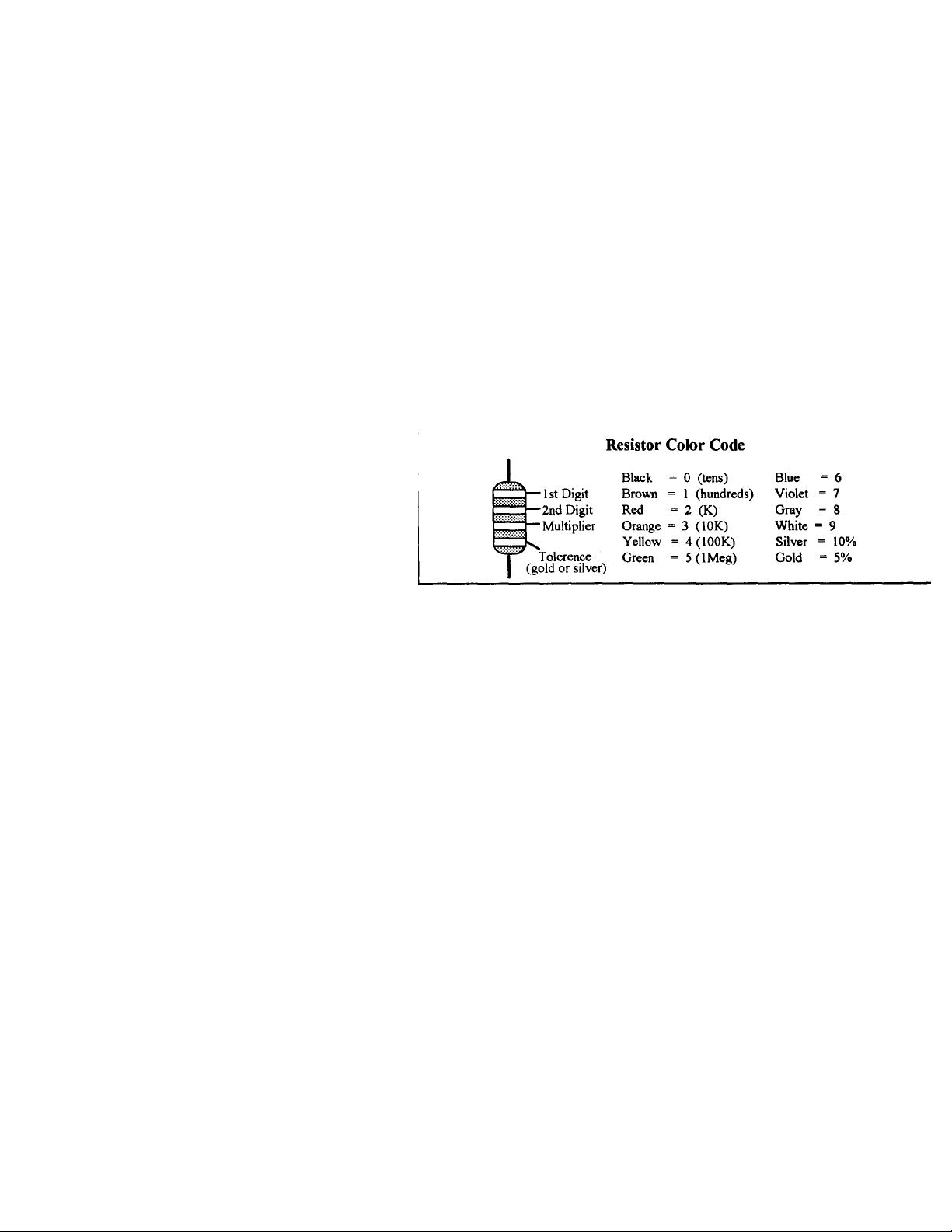
Sorting and Reading Resistors: The electrical value of resistors is indicated by
a color code (shown below). You do n't ha ve t o me mori ze thi s co d e to work
with resistors, but
ou do need to und er sta nd ho w it works:
When you look at a resistor, check its multiplier code first. Any resistor with a
black multiplier band falls between 10 and 99 ohms in value. Brown designates
a value between 100 and 999 ohms. Red indicates a value from 1000 to 9999
ohms, which is also expressed as 1.0K to 9.9K. An orange multiplier band
designates 10K to 99K, etc. To inventory resistors, first separate them into
groups by multiplier band (make a pile of 10s, 100s, Ks, 10Ks etc.). Next, sort
each group by specific value (1K, 2.2K, 4.7K, etc). This procedure makes the
inventory easier, and also makes locating specific parts more convenient later
on during construction. Some builders find it especially helpful to arrange
resistors in ascending order along a strip of double-sided tape.
This VEC kit contains molded chokes which appear, at first glance, similar to
resistors in both shape and band marking. However, a closer look will enable
you to differentiate between the two-chokes are generally larger in diameter
Page 6
VEC-1290K Instruction Manual AM Radio Transmitter Kit
y
p
(
)
and fatter at the ends than resistors. When doing your inventory, separate out
chokes and consult the parts list for specific colo r-co de in formati on.
an
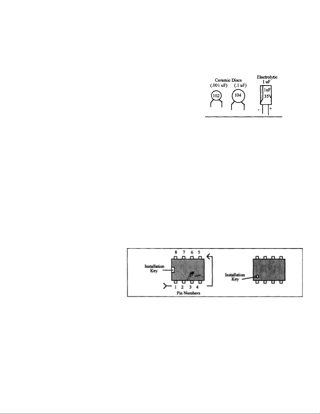
Reading Capacitors: Unlike resistors, capacitors no longer use a color code
for value identification. Instead, the value, or a 3-number code, is printed on
the body.
Value Code
10 pF = 100 Multilayer
F = 101
100
.001 uF = 102*
.01 uF = 103
.1 uF = 104
=
270 pF
As with resistors, it's helpful to sort capacitors by type, and then to arrange
them in ascending order of value. Small-value capacitors are characterized in
pF (or pico-Farads), while larger values are labeled in uF (or micro-Farads).
The transition fro m pF to uF occur s at 1000 pF (or .001 uF)*. Tod ay, while
most monolithic multilayer and disc-ceramic capacitors are marked with a
three-number code, you may still find a .1 uF capacitor marked either "104"
or ".1". For three digit codes, the first two digits indicate a numerical value,
while the last digit indicates a multiplier (same as resistors). The value is in
pF; thus a capacitor marke d "104" i s 100,000 pF, or. 1 uF.
Electrolytic capacitors are always marked in uF. Electrolytics are polarized
devices and must be orie nted corr ectly dur ing inst allatio n. If you beco me
confused by markings on t he ca se, remembe r the unc ut negat ive lead i s
slightly shorter than the positive lead.
Integrated Circuits: Proper IC positioning is indicated by a dot or square
marking located on one end of the devic e. A corre spond ing mark is silkscreened on the PC board and printed on the kit's parts-placement diagram. To
identify specifi c IC pin number s for t esting p urpose s, see the dia gra m below.
Pin numbers always star t at the ke yed end of the case and pro gre ss
counterclockwise aro und the de vice, as shown:
Page 7

-
(y
)
p
p
gray
PARTS LIST
Your kit should contain all of the parts listed below. Please identify and
inventory each item on the checklist before you start building. If any parts are
missing or damaged, refer to the manual's warranty section for replacement
instructions. If you can't positively identify an unfamiliar item on the basis of
the information given, set it aside until all other items are checked off. You
may then be able to identify it by process of elimination. Finally, your kit will
go together more smoothly if parts are organized by type and arranged by
value ahead of time. Use this inventor y as an opportunity to sort and arrange
parts so you can identify and find them quickly.
Q Qty Part Description Designation
1 15 ohm (brown-gree n-bl ack) R2
1 1K ohm (bro wn-bl ac k-r ed ) R3
14.7K ohm
Ca
acitors:
Q Qty Part Description Designation
2 100 pF ceramic disc (101) C9,C10
1 510 pF polst yrene (5 10 ) C8
5 0.1 uF ceramic disc
ellow-violet-red
(104)
R4
C3,C4,C5,C6,C7
Semiconductors:
Q Qty Part Description Designation
1 4049 16-pin DIP i ntegrated c ircuit U1
1LM386 8-
[X] Qty Part Description Designation
1 22 uH molded choke (red-red-black) L2
2 100 uH molded choke (b rown-b lac k-bro wn) L7 ,L8
2 180 uH molded cho ke (bro wn-gray-b ro wn) L5,L6
2 330 uH molded cho ke (ora nge-ora nge-b rown) L4,L9
1 680 uH molded choke (blue-
in DIP integrated circuit U2
-brown) L3
Page 8
VEC-1290K Instruction Manual AM
p
Switches/Jacks/Misc.:
0
Qty Part Description
DPDT push-action switch SW1
1 RCA phono jack, PC-mounted J1
1 2 .1 mm DC coaxial power jack J2
5 2-pin PC board mount headers JMP1,2,3,4,5
2 2 -pin jumpers, shorting
16-pin IC socket
1
181 4" nylon cable tie
1PC board
1 6 ' length of insulated 20-AWG solid wire ANTI
in IC socket
Radio Transmitter
Kit
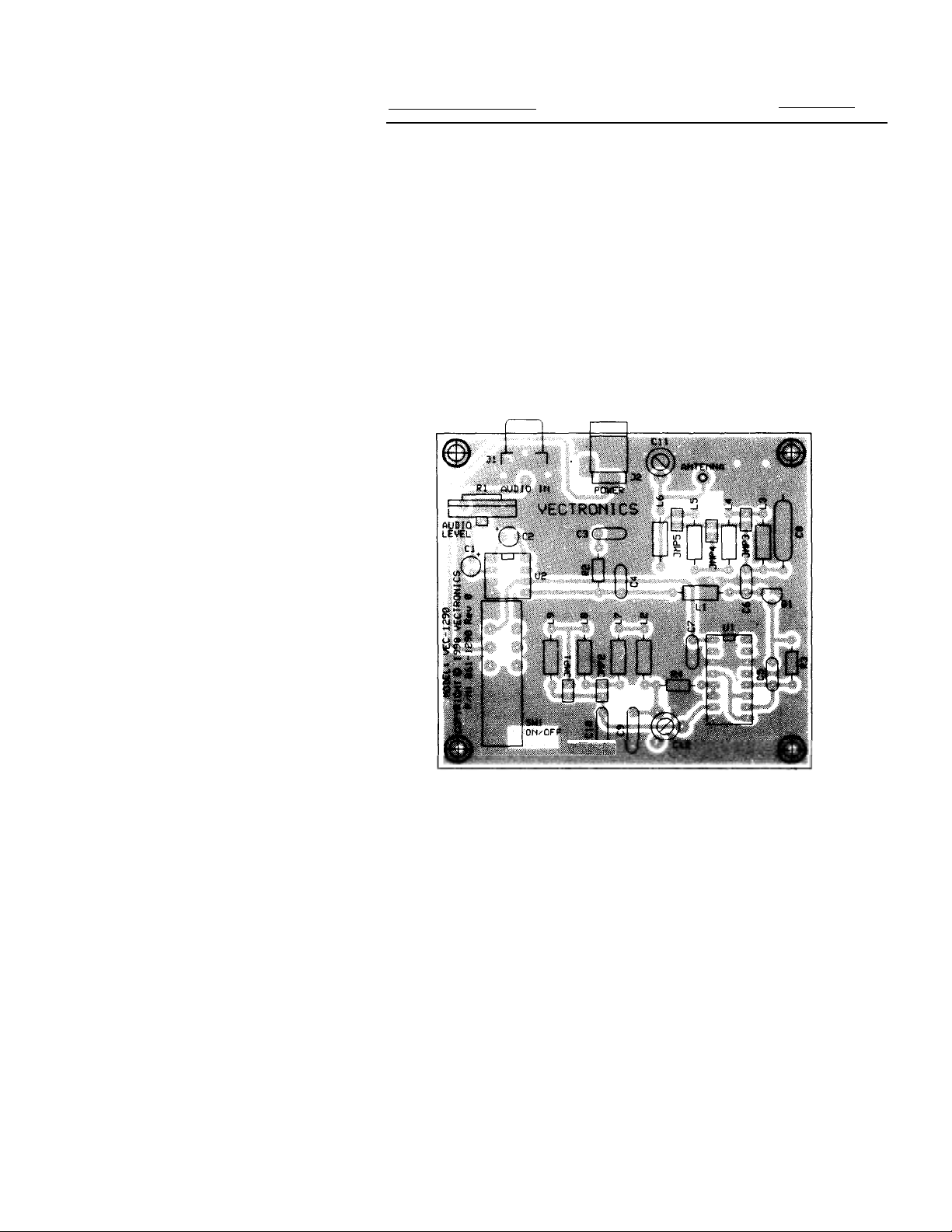
PARTS PLACEMENT DIAGRAM
Designation
Page 9

VEC-1290K Instruction Manual AM Radio Transmitter Kit
p
STEP-BY-STEP ASSEMBLY INSTRUCTIONS
Before assembling your kit, ple ase ta ke time to read and under stand the VEC
kit warranty printed on the inside cover of t his manual. Read thro ugh the
assembly instructions to make sure the kit does not exceed your skill level.
Once construction is started, the kit is non-returnable. Finally, if you haven't
already done so, plea se ver ify that a ll parts li sted in the i nventor y are inc luded.
If anything is missing or broken, refer to the warranty instructions for
replacing missing or damaged pa rts.
First, a few notes and comments t o hel p you along. Part de signators for
components such as R1, C3, etc., appear on the silk-screened legend on the
component-mounti ng sid e of the p rinted c ircuit bo ard. T hese co rrespo nd to
the drawing shown in
are inserted on the silk-screen side of the board. All capacitors should be
installed with their bodies as close to the PC board as possible; this is very
im
ortant in RF circuits.
If you have last-minute que stio ns concer ning what to ols or materi als are
needed to assembly this kit, please refer back to the section entitled
YOU BEGIN.
PARTS PLACEMENT
section of this manual. T he par ts
BEFORE
"Install"
When you are direc ted to in stall a part, this means to locate, identify,
and insert the part into its mounting holes on the PC board. This includes prebending or straighte ning lead s as needed so force is not req uired to seat the
part. Once a component is mounted, bend each lead over to hold it in place.
Make sure trimmed lead s don't to uch other pad s and trac ks, or a short circ uit
may result:
Not Good
"Solder" When you are directed to solder, this means to solder the part's leads
in place, and to inspect both (or all) solder connections for flaws or solder
bridges. If no solder ing prob lems are no ted, nip off t he exce ss protrud ing
leads with a sharp pair of side cutters.
Begin assembly by installing the '/,-watt fixed resistors. Because these are all
5-percent toler ance e nding with a fo urth gol d color ba nd, you ne ed only re ad
the first three bands of the color code during the following steps. All resistor
Page 10

VEC-1290K Instruction Manual AM Radio Transmitter
g
)
p
p
leads should be formed as sho wn belo w. Install and so ld er re sistors at the
followin
Important Note: the fourth resistor color ban d is f o r tolerance, and is not called
out in the following steps.
locations:
1. Find the 15-ohm (brown-green-black) '/,watt resistor.
2. Install the 15-ohm resistor at R2 on the printed circuit board.
3. Solder and trim the leads.
4. Find the 1K-ohm (brown-black-red)
1
/4-watt
resistor. 5. Install and solder at R3.
6. Find the 4.7K-ohm (yellow-violet-red) '/.-watt
resistor. 7. Install and solder at R4.
9. Check each solder joint. Look for solder splashes, bridges (a bridge is
where solder has made a connection between two or more points
that should not be connected
Phase 2: Jum
er Headers
[ ] [ ] 1. Locate the five 2-
in jumper headers.
, or poor solder conne ct io ns.
Short pins into
pc
O O board holes
Page 11

-
,
,
C8
Important Note: When installing the two-pin jumper headers, the shorter pins
are inserted into the pc board.
10. Locate the two 100-pF ceramic trimmer capacitors. When inserting,
ensure that the three component leads are fully seated and that the
capacitor body is level. Install and solder at the following locations:
-
12. C12 100-pF trimmer
13. Locate the 510-pF polystyrene capacitor. This part may be
marke 511
or with 510 using the old m a r k ing code system.
14. Install and solder the 510-pF (510 or 511) polystyrene capacitor al
.
Page 12

VEC-I290K Instruction Manual AM Radio Transmitter
(
(
g
(
f
Important Note: only the first three color bands are specified in the following
directions. The fourth band is for tolerance and may be disregarded.
1. Locate the 1000-uH molded choke (brown-black-red). Install and
solder at location L1.
2. Locate the 22-uH molded choke (red-red-black). Install and solder at
location L2.
3. Locate the 680-uH molded choke (blue-gray-brown). Install and solder
at location L3.
4. Locate the two 330-uH (orange-orange-brown) molded chokes. Install
and solder at locations:
5. L4 330 uH
6. L9 330 uH
7. Locate the two 180-uH (brown-gray-brown) molded chokes. Install and
solder at the following locations:
8. L5 180 uH (brown-gray-brown).
9. L6 180 uH (brown-gray-brown).
and solder at the followin
11. L7 100 uH (brown-black-brown).
12. L8 100 uH
rnase 5: IC Sockets/ICs
1. Locate the 8-pin DIP IC socket. Note that the socket is "keyed", and
should be installed with its key aligned to the silk-screened outline
on the PC board.
orange-orange-brown).
orange-orange-brown).
brown-black-brown).
Top view o
1 2 3 4 Pin
Page 13

Page 14

-
p
g
2. Locate the 2N3904 plastic transistor. Form its leads so it sits close
to the board at location Q1. Note that the device has a rounded and
flat side. Align the package to conform to the silk-screened legend.
Solder and trim.
Phase 7: Electrolytic Capacitors
Electrolytic capacitors are polarized devices, and must be inserted with
respect to polarity. The style used in the VEC direct conversion receivers
have radial leads; both leads exit from one end of the device body. Each
capacitor's plus (+) mounting holes are noted both on the circuit board and
parts placement diagram. If the markings on the capacitor body are unclear,
the plus (+) lead is the longer of the two.
1. Locate the two 10-uF electrolytic capacitors. Install and solder at
following locations. Observe the polarity markings!
2. C1 10uF
Phase 8: The Finishing Touches
1. Locate the IOK-ohm vertical trimmer resistor. Install at location RI.
Be sure the
2. Locate the RCA PC-board mount phono jack. Install at location Jl. Be
sure the jack is fully seated, solder.
3. Locate the 2.lmm coaxial power jack. Install at location J2. Be sure
the jack is fully seated, solder.
4. Locate the six-foot len
5. At one end, strip
ot is fully seated to the board, and solder the three leads.
th of white insulated 20-AWG antenna
'/a"
of insulation from the wire.
Page 15

-
g
g
7. Find the 4" nylon wire tie. Secure the antenna wire to the PC board
using the wire tie as shown below. Pull the tie wrap tight, and trim
excess tie len
th.
8. Locate the two plastic shorting jumpers. Put these in the parts bag
until needed for the ali
nment procedures.
9. This completes the assembly of the VEC-1290K AM radio transmitter.
Please go over the board and verify that all parts are properly
installed. Check all solder connections, and redo those that look
suspect.
TESTING AND ALIGNMENT
Before attempting any adjustments, the entire section dealing with Alignment
and Testing should be read, and some familiarity with the Operating
Instructions section is also advisable. The transmitter requires a suitable
external power and audio source for alignment and operation.
Initial alignment sets the transmitter to the desired operating segment of the
AM broadcast band. The VEC-1290K oscillator stage covers the AM band in
three preset ranges. These are determined by the presence or absence of a
jumper at locations JMP1 and JMP2. Fine tuning within each of the
three ranges is set by trimmer capacitor C12.
Oscilla t o r freq uency ra n 'reset
540kHz to 870kHz no jumper
870kHz to 1420kHz JMP1
1 l70kHz to l7l0kHz
Table 1
,
Page 16

Page 17

'
g
g
y
-
clip on JMP 1. Capacitor C 12 will now tune the transmitter frequency from
A frequency counter is the quickest method to set the transmitter precisely on
channel. Attach the counter input to either side of resistor R3. The signal is
strong enough at thi s p oi nt to dr ive any 50 -o h m or high -i mpe d anc e c ount er
without problem.
A portable radio can also be used. Set the radio to the clear frequency, and
apply an audio source to the transmitter. (This is discussed in the OPERATING
INSTRUCTIONS section.) Slowly tune C12 until the transmitter is heard on the
radio.
Hint: Store unused shorting clips where they won't become lost. Place unused
shortin
clips over one pin of open junipers.
Antenna Matchin
Important Note:
operated only with the supplied 6-foot antenna wire. Attempting to use other
antennas will result in a severe mismatched condition, reduced range and
distorted audio. The antenna wire should be run out straight, avoiding
proximity to nearby metal objects. If more range is needed, try relocating the
transmitter to a different location.
Once a clear channel has been found, and the oscillator set to frequency, the
antenna matching ne t work must b e t uned . Re fer to Tab le 2. Not e tha t so me
frequencies, such as 800 kHz, can be matched by one of two possible jumper
configurations. T r y bot h, a nd use t he o ne whic h wor ks be st. Using t he p r evio us
example where the oscillator was set to 910 kHz, Table 2 shows the proper
antenna match range is selected by placing a shorting clip across the pins of
JMP4. (910 kHz falls between 730 kHz and 1400 kHz.)
When the prop er a nte nna matc hi n g ra nge ha s b ee n set, c apa cito r CI I is tuned
for maximum radiated signal. This can be done by carefully adjusting CII while
increasing the distance between the transmitter and a portable radio. As the
signal grows weaker with distance, adjust CI I for the loudest signal.
If
ou have access to test equipment, the following steps may also be
Using an oscilloscope: If your oscilloscope has a vertical amplifier with
useable bandwidth to at least 2 MHz, you may attach the probe to the junction
of ANT 1, C 1 I and L6 as shown on the schematic. C 11 should be peaked for
maximum scope amplitude. A low-capacitance 10:1 probe is recommended to
avoid detuning.
:
For reasons given later, the transmitter is designed to be
Page 18

-
y
y
Using afield strength
the schematic b elow show s a simpl e and easi ly const ructed RF field st rength
meter. Most of the parts can be found at Radio Shac k. Assembly is not critic al
due to the ver
The diode must be a germanium type.
run near the VEC-1290K transmitter antenna. Adjust C11 for a maximum DC
voltage reading on the vo ltmete r. Ke ep the fi eld s treng th mete r pick up an tenn a
wires as far from the transmitting as possible to prevent interaction. Use the
lowest DC volt age setti ng on t he voltmet er for m aximum se nsitivit y. Some
voltmeter test l ead jacks may allow th e diode leads to be slipped between the
test lead plugs and meter jacks-if so, the meter leads may be spread apart and
low operating frequencies.
indicator: If you have a general purpose volt-ohmmeter,
The 3-foot wire "antennas" should be
Audio Gain Setting:
The VEC-1290K will accommodate a wide range of audio levels, from "line level"
cassette or CD deck feeds, or even the very low output from a local mike.
Removing capacitor C2 will reduce the amplifier gain; this is t he preferred
configurati on fo r us uall y hi gh l ine -leve l audio sour ces suc h a s wh en t akin g a n
audio fe ed di re ctl
Setting the
Setting the gain con trol too hig h results in over modu lation and considera ble
audio distortion The proper setting for the gain control RI can be found by
starting at it lowest setting, and with an audio source connected, slowly
increasing the gain the control until the audio starts to sound raspy or clipped.
Once clipping is heard, the control setting should be reduced until the
distortion,go es away. This is most noticeabl e on music sources. Exp erienced
technicians may use an oscilloscope to observe the RF modulation envelope for
from a speaker output.
gain
control.
The gain control sets the modulation percentage.
Page 19

VEG1290K Instruction Manual AM Radio Transmitter
purp
p
y
f
p
y
The VEC-1290K should be mounte d in an enclo sure. V ectroni cs has de sign a
matching enclosure for the VEC-1290K. The matching enclosure is anal metal
box which includes knobs, hardware, decals, and rubber feet. (Model VEC1290KC.) If you wish to supply your own, RadioShack offers several styles that
are suitable for this
ose.
Power requirements:
source and draws about 100 mA. Wall-plug power supplies are an ideal sour of
ower, but should have the following specifications:
1. Internall
2. Rated for at least 300 mA continuous
3. Be equipped with a 2. 1 mm co axi al power jack,
The VEC-1290K can be operated at lower supply voltages down to about 9
volts, but the transmitter range will be reduced. T he transmitter is powered
when the SW1
Once set to frequency, and the antenna tuned, the only control that needs be
Your home studio:
audio-CD players, tape or cassette decks, or even a local microphone for the
budding DJ or tal k show host . Unless a singl e audio sour ce is goi ng to be use d,
the audio gain control R1 will have to be continuously adjusted for each new
audio source. T ape deck s and cass ette pl ayers pr ovide "li ne level" audio o utputs
for interconnections between decks and amplifiers. Microphone produce much,
much lower signal levels. As mentioned in the alignment section, capacitor C2
Using a "mixer":
four or five channel mixer may be used between the various audio sources and
the transmitter audio input. The mixer will allow the level for each source to be
set individually so all of your audio feeds will be balanced when played on the
air. The mixer master out put can be us ed to set the modul ation li mits. The level
controls can be used to "fade" into one source from another, just like disc
jockies do on the air! You can also use an inexpensive graphic equalizer to tailor
your station's on-the-air sound-but the VEC-1290K as-is rivals the fidelity of
man
iltered
FM broa dcas t st atio ns!
The VEC-1290K operates from an external 12-volt D
and
regulated
ush shaft is in the depressed position.
The VEC-1290K will accommodate various sources of
To give your home station that "pro" sound, an inexpensive
12-volt DC
center pin
Other uses:
that is being used on a DSS satellite s ystem to play the Mu sicChoic6m Big
Let your imagination be your guide! We know of one VEC-1290K
Page 20

VEC-1290K Instruction Manual AM Radio Transmitter
g
g
p
Getting the most range: The transmitter antenna system is most efficient at the
higher frequencies. The new expanded AM broadcast band between 1610 and
1710 kHz is still relatively free of new station assignments. Likewise, many
VEC-1290K's will make it down to as low as 530 kHz, a relatively quiet
frequency in most areas.
Try to locate the VEC-1290K transmitter in area that is free of metal support
structures. Remember that the VEC-1290K may be remotely located; use
shielded audio cable to run between the transmitter audio input back to the
"station" location. Another "trick" you may try is attaching a good ground to
the transmitter cabinet. This will improve the antenna radiation efficiency.
Always run the six-fo o t a ntenna wire in a str aight line , ne ver c oi led or z igzagged.
Understandin
the FCC rules:
Federal Communica tio n Commission (FCC) rules a nd r egul ati ons go ve rning
unlicensed AM broadcast transmitters are complicated and technical. Devices
such as the VEC-1290K AM transmitter are covered under Part 15 of the FCC
rules and regulations.
Part 15 rules pe rmit a maximu m fie ld str engt h o f 24000/fkH
uV-per-meter at
z
30 meters, between 510 kHz and 1710 kHz. The rules also permit a 100-mW
transmitter with a ten-foot antenna, including the feedline. In order to meet Part
15 regulations, the transmitter output must be kept below 2 volts rms when
using a 50-ohm ante nna . The high-impedanc e a nte nna a nd po wer l eve l o f the
VEC-1290K meet FCC Part 15 requirements.
Your responsibilities under Part 15. Unlicensed devic e s op er ati ng und er Pa rt
15 must not cause interference, and must accept interference as a part of their
operation. What does this mean in plain English? If your station is causing
interference to the reception of a licensed broadcast station in your neighbors'
radios, you are in violation of FCC rules and are operating illegally. Either
operation must be susp end e d, or a ne w clea r fre q uenc y found. If
broadcast stations are interfering with your broadcasts, this is something you
must accept being a micro-broadcaster unde r FCC P ar t 15 re gulat io ns. .
Here are some
uidelines to
1. Identify your station regularly, stating your location and purpose. Do not
make up FCC call letters! You can use an ID along the lines of "This is
Radio 910, operating from New York City".
2. Never transmit false distress signals!
3. Avoid
rofanity or indecency.
Page 21

Only high-quality components and proven circuit designs are used i Vectronics
p
g jump
pply
(
kits. In very rare instances is a defective component the source of problem.
Replacement of defective parts is covered in the Warranty section Ninety-five
percent of the kits returned for factory repair are due to solderin problems or
parts in the wrong locations. We advise repeating the assembl instructions stepby-step, looking for mistakes or soldering problems. Be especially wary of
electrolytic capacitors and semiconductors. Kit builders often miss obvious
mistakes. What is needed is a "fresh" set of eyes. Enlist a friend to go over your
work.
Always check the obvious! Is the power supply plugged in? Is the power switch
Low range: Check power supply voltage, alignment of C11 and proper jumper
configuration fo r a ntenna matchi ng c ir cui t. Chec k ant en na wire co nne ct io n at
ANTI o n
Audio distorted: Gain control set too high. Capacitor C11 improperly tuned, or
wron
Loud hum on audio: Bad audio cables, check for broken shield wires. Power
su
c board. Antenna not located in an optimum location.
er configuration for a nte nna matc hing circuit.
filtering poor.
Osciilator dead: CMOS device U1
Carrier signal, no audio: Bad audio cables, RI set to minimum. IC U2 (LM386)
defective.
4049A) defective.
Page 22

Technical Circuit Description:
p
p
RF oscillator section:
One section of six-section inverter CMOS IC package is
used for the oscillator (UID). The oscillator tank coil is made of four inductors
in series. Two sets of shorting jumpers allow the inductance value to be set
from 122 uH to 552 uH. Each of the three possible jumper configurations
covers a portio n of the 5 30 to 1710 kH z AM br o adc ast band . Fi ne t uning to an
exact channel is done via a 100-pF ceramic trimmer across the tank coil.
Buffer and driver stages:
The oscillator output is buffered by section UIB of
the 4049 inverter chip. The output of UIB drives two inverter gates in parallelU 1 D and U 1 E.
The paralleled operation insures sufficient drive level the final transistor for
Class C o
Final amplifier stage:
eration.
A 2N3904 transistor is used for the power amplifier
stage. The transistor is biased for Class C 'operation. ``Class C operation
permits the use of high-level modulation for best linearity and efficiency. Note
that many inexpensive AM transmitter kits use modulated oscillators, with
resulting
FM'ing of
the carrier and a maximum modulation level
of
perhaps 25
to 30 percent.
Audio Amplifier and Modulator stage :
Low level microphone or line-level
audio is amplified by a LM386 audio amplifier IC. The audio level to the IC is
set by gain control R1. The output from the IC is directly applied to the RF
power stage, the 2N3904 transistor.
The DC output
of
the LM386 is normally at
''/s
of
the supply voltage with no
signal. The DC level follows the audio signal; at maximum modulation (100%)
the instantaneous output voltage will vary from near zero to almost the full
supply voltage. In a true Class C stage, doubling the supply voltage will
produce a peak power level (PEP)
of
four times the carrier power.
Direct coupling:
After C1, all audio stages up to the PA transistor collector are
DC coupled, with no interstage coupling capacitors or modulation transformers
to limit or tailor the audio res
Antenna and matching:
onse.
The VEC-1290K is supplied with an attached 6-foot
wire radiator. This antenna meets current FCC Part 15 requirements for
unlicensed RF transmitters. The antenna is extremely capacitive reactive at
broadcast band frequencies, and presents a very high impedance to the
transmitter. Capacitor C8, inductors L3, L4 and L5, and trimmer capacitor C11
form a pi-network impedance transformation network to match the
Page 23

antenna to the low-impedance of the final RF stage transistor. Jumpers
are used to select the optimum amount of inductance for segments of the AM
band. Trimmer capacitor C11 allows for a precise match at the operating
frequency-or, maximum transfer of RF energy to the antenna. The pinetwork is in essence is a low-pass filter configuration, and also offers some
degree of harmonic energy rejection.
Page 24

Page 25

-
(
g
p
g
p
p
g
Vectronics has designed a matching enclosure just for your VEC-1290K AM
Radio Transmitter Kit. The matching enclosure is an all metal box which
includes knobs, har dware, de cals, and rubber fe et. Mod el: VEC-1 290K C.
To install your receiver in the VEC-1290KC matching enclosure follow these
instructions
1. Find the front panel deca l and rear panel dec al; separate using scissors. P ut
the rear panel decal on first. This is done by: a.) Remove all debris and oil
from the chassis. b.) Remove the crack and peel to expose the adhesive.
c.) Place the decal on the rear panel without securing it completely. d.)
Gently rub the alignment circles with your finger--if the circles are
centered in the enclosure holes (also check the corner alignment marks)
secure the decal by rubbing and removing all air bubbles. e.) If the
alignment circles are not centered, adjust the decal accordingly then
secure. f.) Use a penknife, or small Exact6m knife, to cut away the unused
edges and cut out the component holes . g.) Repeat this procedure for the
2. Next, install the two L-brackets on the chassis using two of the 3/16"
screws. The longer side of the L-bracket must be connected to the chassis
using the two holes centered on each edge of the enclosure. Refer to the
dia
read all instructions before beginning ... take your time):
ram on the next page for location and orientation.
3. Install the four 1/2" mounting scr ews next. Insert t he screws, fr om the
bottom, through the four hol es relat ively clo se to each corner o f the
chassis.
4. Placethe four 3 /16" round s
5. Now insert the PC board. This must be done by: a.) inserting the front of
the PC board at an angle, b.) then push down on the rear of the board.
Make sure the mounting screws align with the mounting holes in the PC
board before pushing.
6. Use the four hex nuts to secure the PC board. Be certain all appropriate
com
onents are centered with the enclosure holes before tightening.
7. Find the switch cap. Align the switch cap with SWl and push it on. If it is
difficult to
8. The top should now be installed. Use the two remaining 3/16" screws for
securin
9. Place the four rubber feet on the bottom of the enclosure at the
comers.
ush on, then rotate it 90° and try again.
the top to the L-brackets.
acers on the mountin
Page 26

 Loading...