

Page 1

IMPORTANT WARRANTY INFORMATION! PLEASE READ
Return Policy on Kits When Not Purchased Directly From Vectronics: Before continuing
any further with your VEC kit check with your Dealer about their return policy. If your Dealer
allows returns, your kit must be returned before you begin construction.
Return Policy on Kits When Purchased Directly From Vectronics: Your VEC kit may be
returned to the factory in its pre-assembled condition only. The reason for this stipulation is,
once you begin i nsta lli ng a nd sol deri ng pa rt s, you essenti al ly tak e over the rol e of the devic e's
manufacturer . From this point on, neither Vect ronics nor its dea lers can reas onably be held
accountab le for the qua lity or the outcome of your work. Because of this, Vectronics cannot
accept return of any kit-in-progress or completed work as a warranty item for any reason
whatsoever. If you are a new or inexperienced kit b uilder, we urge you to read the manual
carefully a nd determine whether or not you're r eady to tak e on the job. If you wish to c hange
your mind and return your ki t, you may--b ut you must do i t before you begin c ons tr uc ti on, a nd
within ten (10) working days of the time it arrives.
Vectronics Warrants: Your kit contains each item specified in the parts list.
Missing Parts: If you determine, during your pre-construction inventory, that any part is
missing, please contact Vectronics and we'll send the missing item to you free of charge.
However, before you contact Vect ronic s, please look carefully to c onf ir m you haven't misr ea d
the marking on one of the other items provided with the kit. Also, make certain an alternative
part hasn't been substituted for the item you're missing. If a specific part is no longer
available, or if Engineering has determined that an alternative component is more suitable,
Vectronics reserves the right to make substitutions at any time. In most cases, these changes
will be clearly noted in an addendum to the manual.
Defective Parts: Today's electronic parts are physically and electrically resilient, and
defective components a re r a re. However, if you disc over a n it em duri ng your pr e- c onst r uct i on
inventory that's obviously broken or unserviceable, we'll replace it. Just return the part to
Vectronics at the address below accompanied with an explanation. Upon receipt, we'll test it.
If it's defec tive and appear s unused, we'll ship you a new one right away at no charge.
Missing or Defective Parts After You Begin Assembly: Parts and materials lost or
damaged after construction begins are not covered under the terms of this warranty. However,
most parts supplied with VEC kits are relatively inexpensive and Vectronics can replace them
for a reasonable charge. Simply contact the factory with a complete description. We'll
process your order quickly and get you back on trac k.
Factory Repair After You Begin Assembly: Kits-in progress and completed kits are
specifically excluded from coverage by the Vectronics warranty. However, as a service to
customers, tec hnicia ns ar e availa ble t o evaluate a nd repai r malf unctioni ng kits for a minimum
service fee of $18.00 (½ hour rate) plus $7.00 shipping and handling (prices subject to
change). To qualify for repair service, your kit must be fully completed, unmodified, and the
printed circuit board assembled using rosin-core solder. In the event your repair will require
more than an hour to fi x (or $36.00, subject to change), our technicians will contact you in
advance by telephone b efore p erforming t he work. Def ective unit s should b e shipp ed prep aid
to:
Vectronics
1007 HWY 25 South
Starkville, MS 39759
Page 2

When shipping, pack your kit well and include the minimum payment plus shipping and
handling charges ($25.00 total). No work can be performed without pre-payment. Also,
provide a valid UPS return address a nd a day time phone number where you may be reac hed.
Page 3

VEC-121K Owner's Manual Crystal Radio Set Kit
INTRODUCTION
Relive those bygone days of radio--a time almost 90 years ago, when early radio
pioneers experimented with crystal radio receivers! Wind your own “inductor”
coil, wire up the earliest radio circuit; and, there’s no soldering needed!
Everything is assembled on a pine “breadboard”, just like great, great granddad
did when he was a youngster. Lear n ab o ut b a sic r a di o theo r y. Put up an antenna
(wire included), connect a ground, and experience the magic of a radio that
needs no power. A special high-sensitivity earphone allows you to hear AM
Broadcast signals from many miles away; this little baby really performs. The
VEC-121K is a fascinating project for youngsters of all ages!
The VEC-121K features a modern “fixed detector”, eliminating the need for
frequent and frustrating catwhisker adjustments. A large, Hi-Q antenna coil, and
a modern miniature Hi-Q tuning capacitor, are used for best sensitivity and
selectivity. The high-impedance parallel-resonant tuning circuit allows a short
receiving antenna to deliver maximum signal to the set.
TOOLS AND SUPPLIES
Having the right too l to do a job always makes things go be tter. There is no
soldering required, and only a few basic hand tools are needed to assemble your
VEC-121K crystal radio set.
This is a list of the tools you will need:
SAFETY EYEGLASSES or GOGGLES!
parts is a lot of fun, but please, safety first! Your local hardware store carries
inexpensive safe ty goggles. Befo re you are go ing to be cutting or wor king with
wires, hammering, handling any chemicals, or using any tools, put on your
safety eye wear first!
1.
Phillips screwdriver.
kit, and we will use this tool when it is time to mount parts on the wood
board. Try to find a screwdriver with a shaft (the distance between the tip
and start of the handle) that is at least 3” long.
2.
Long-nose pliers.
by electricians. The long slender nose makes it easy to hold or bend a wire
that is being worked on.
3.
Wire cutters.
long-nose pliers styles feature built-in wire cutters. Wire cutters are
sometimes called “nippy cutters” or “diagonal wire cutters”—depending on
how they’re made.
These special pliers have sharp cutters to cut wires. Some
There are eight Phillips head screws included in the
These pliers have a long and tapered nose and are used
Working with wires, tools and radio
1
Page 4

VEC-121K Owner's Manual Crystal Radio Set Kit
4.
Ruler or tape measure.
5.
Small penknife.
A penknife, or small E xacto
A small 12” ruler or flexible tape measure will do.
TM
knife, is needed to scrape
off wire insulati o n. If you a r en’t o l d e no ugh to use a knife , a small se ct io n o f
sandpaper will do.
6.
Small Hammer.
It will be used with a finishing nail to mark where the
screw holes are placed on the pine board.
7.
Small-Screwdriver or Hex-Tool
. Size to fit the set screw in the tuning
knob--depending on which type of knob is supplied with your kit.
Radio Shack carries many inexpensive small hand tools for electronics work.
Here are some items that will come handy:
1.
Masking tape.
2.
Cyanoacrylate adhesive.
is sold as “Super Glue
This is the fancy name for contact cement, which
TM
” or “Crazy GlueTM ”. You’ll use the contact cement
to hold the coil windings in place. These adhesives are very strong, and can
instantly glue your fingers t ogether i f you are not c areful! If you ar e not old
enough to work with co ntact cements, have someone who is o lder help you
when gluing is directed in the instructions. The glues used to assemble
plastic model airplanes are safer to work with and may also be used instead
of super glue. However, they will require a longer time to dry. Always have
an adult advise and supervise your use of any chemicals!
WOODWORKING AND FINISHING (OPTIONAL)
Perhaps this is your first kit building experience, or your first homemade
receiver project. If so, your VEC-121K crystal receiver will be a source of pride
for many years to come. Before assembling this kit, you might wish to consider
sanding and staining the pine board—this will bring out the beauty of the wood,
and make your project look as if it was done by an “old pro”. Many early radios
were built in what was called “breadboard” fashion. The radio parts were laid
out on a small section of wood board.
Early radio parts were very expensive, even a simple crystal radio set could cost
a week’s pay! Most experimenters had to improvise. Often an old breadboard
(used to roll out bread dough) was used as a base to mount radio parts. If you
were well-to-do, your “breadboard” was probably a fine piece of mahogany or
walnut board!
Sanding:
Before applying a stain finish, carefully sand the pine board using 200
grit sandpaper. When sanding the surfaces, always sand in the direction of the
grain to avoid scratching the wood. The two board edges that expose the end
2
Page 5

VEC-121K Owner's Manual Crystal Radio Set Kit
grains of the wood will be rather rough to the touch, and will require some extra
sanding to produce a smooth even surface. You may have to use a 150 grit in
the beginning on the end grains. Sanding is best done outdoors. Wear a
disposable paper dust mask while sanding.
Finishing:
Your local hardware store stocks small cans of woodworker stains.
Either a walnut or mahogany wood stain finish is a good choice. Both oil-based
and water-based stains are availab le. We suggest using a water-ba sed stain for
this project—it is easier to work with and easier to clean up afterwards. You
will need a clean cloth, or staining cloth, to apply the stain. Follow the
manufacturer’s directions very carefully, and read the safety information on the
label. Use dispo sable la tex gloves when hand ling stain. If you’re too young to
safely work with wood stains, ask an adult for assistance with this portion of the
project. Always handle any chemicals with great care!
Important Note:
begin. Before attaching the tuning capacitor with the double-sided adhesive
tape, the board should be allowed to dry for a few days. This will allow the stain
to fully cure, or dry, so it does not interfere with the tape adhesive.
Once the stain is dry to the touch, the assembly work may
BEFORE YOU START BUILDING
Your work area:
what you are doing. At times we will need to set items aside to allow glue to
dry; or you will need to stop working on your project for other activities. Your
work area should be in a place where your project does not interfere with others.
Keep your work area clean and free of clutter. Kit parts should be kept in the
box until you need to use them. When you are finished for the day, return the
tools to their proper place. Put unused kit parts back in the box so you will not
lose them. I f you are old eno ugh to use glues and wood stains, you may have
younger brothers and sisters who aren’t! Keep chemicals out of the reach of
younger children.
Use a good workbench with good lighting so you can see
Following directions:
Kits are built in “steps”. These steps follow a logical
order, that means following the instructions will make your kit building
experience easier and ensures that your project will work first time when
finished.
You will notice a check box ! as each instruction gives you a simple task, or
direction, to follow. When the task is finished, make a small check mark in the
box to show that part has been completed. This will allow you to keep track of
where you left off when returning from a break.
For example, a direction may read:
3
Page 6

VEC-121K Owner's Manual Crystal Radio Set Kit
!
Tighten the screw until snug, this will make a good electrical connection
between the Fahnstock clip and wire.
When finished following the directions, “check off” that the step has been done.
"
Tighten the screw until snug, this will make a good electrical connection
between the Fahnstock clip and wire.
Don’t rush!
Have you ever notic ed that when you try to rush do ing something, it never turns
out right? Don’t try to build the crystal set receiver in one day! The time spent
building a kit is most of the fun. We will be “breaking down” the kit assembly
into several phases. For example, the first phase is preparing the “breadboard”.
The next kit phase involves winding the c oil.
Working with wire:
Unspooling:
Your kit includes a 100-foot roll of 18 AWG enamel-coated wire.
This wire is used to wind the tuning coil, for your receiver’s antenna, and is also
to be used for making connections between the radio components. Do not
remove the wire tie from the roll of wire until you are ready to use it. There is a
right and wrong way to remove wire from the spool! Never allow the wire to
uncoil, like a Slinky
TM
toy! Doing so will cause the wire to twist and make kinks
when you try to use it. Instead, hold the spool of wire in both hands, and
carefully unroll the wire from the spool. Re-tape the unused portion when
finished.
Removing insulation:
Electrical connections are made by removing the
insulation from the enamel wire. When you need to make an electrical
connection, you will be instructed to remove the wire insulation. We will tell
you where the insulation should be removed, and how much to remove. This can
be done by using a small piece of 150 grit sandpaper. Fold the sandpaper in half
so the “sandy” sides face together. Place the wire into the sandpaper fold, and
slide the sandpaper back-and-forth over the wire while applying a gentle
pressure. Turn the sandpaper every so often to fully remove all of the insulation.
Gently scraping the insulation with a small penknife will also work. Lay the wire
on a piece of scrap board, and draw the knife blade over the insulation to scrape
it away. Always scrape in a direction away from your body!
All of the insulation must be removed to make a good electrical connection. The
bare area of the copper wire should be bright and shiny when you are finished.
Making connections:
The directions will tell you to make one of two types of connections: “End”
connections or “through” connections.
4
Page 7
VEC-121K Owner's Manual Crystal Radio Set Kit
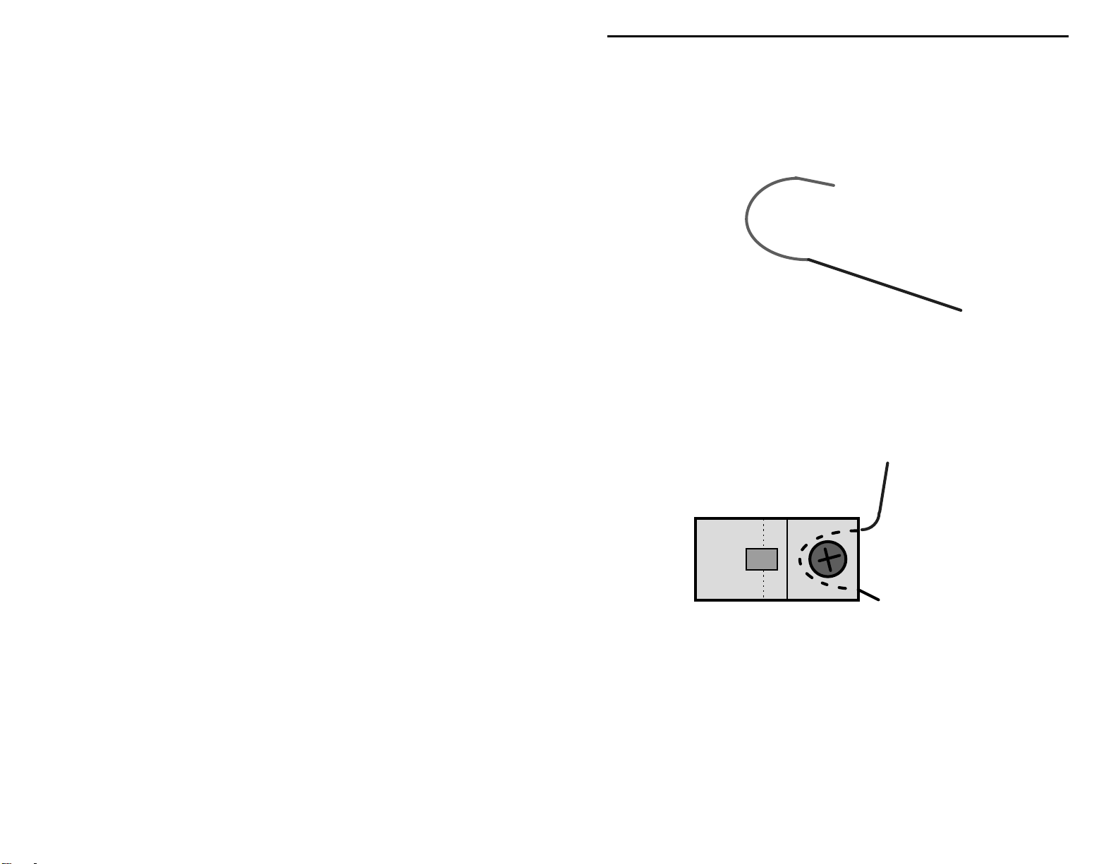
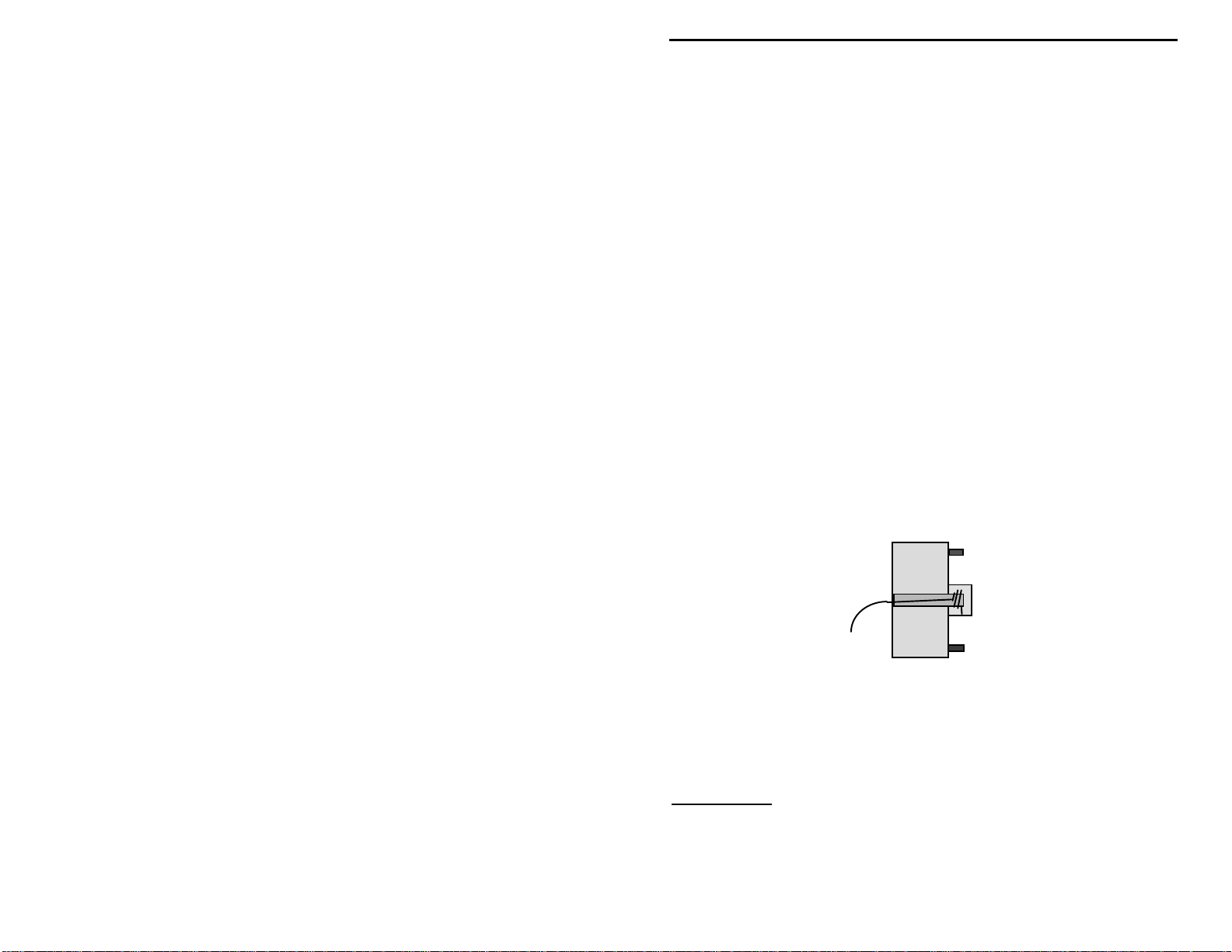
End Connections:
connected. To make an end connection, you will have to remove about 1” of
insulation from the wire and form the end into a “fishhook” shape, as shown
below.
In the following drawing, a wire end connection is used to make an electrical
connection to one of the Fahnstock clips mounted on the pine board. Note we
show the wire as a “dotted line” where it passes under the Fahnstock clip. When
the Phillips screw is tightened, a good electrical connection is made. The
drawing shows how the wire hook is placed between the Fahnstock clip and
board.
End connections are made when the end of a wire is
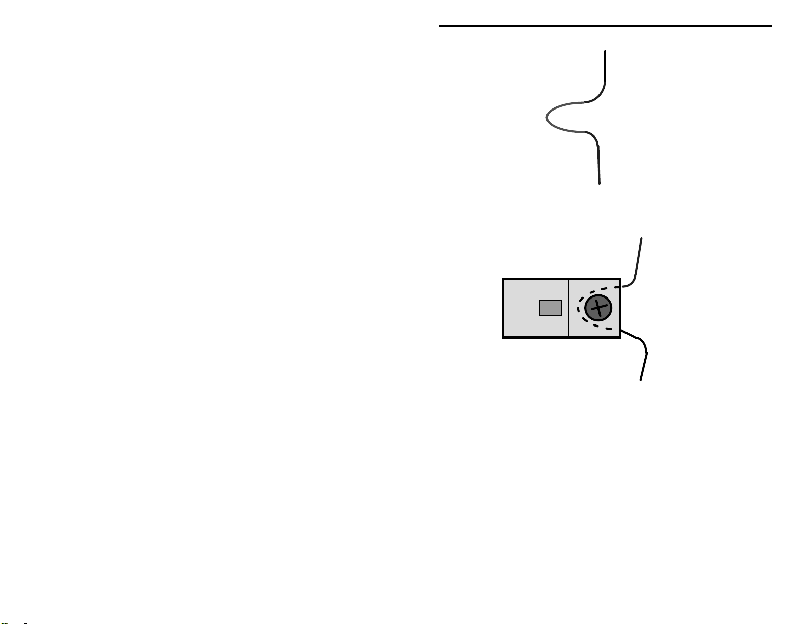
Through conne ctions are used when the wire goes to a electric al connecti on at a
Fahnstock clip, and then continues on to make one or more connections to other
points. T he directions will tell where to make a through connec tion on a wire,
and how much insulation needs to be removed.
5
Page 8
VEC-121K Owner's Manual Crystal Radio Set Kit
The wire insulation is removed where shown in the directions, and made into a
half loop as shown above.
The above d rawing shows a through c onnectio n being made to a Fahnsto ck clip.
The dotted line shows where the wire runs under the clip body.
6
Page 9

VEC-121K Owner's Manual Crystal Radio Set Kit
PARTS LIST
You are just about ready to begin your kit building adventure! But first, let’s
take a few minutes to make sure everything needed is present and accounted for.
If any parts a re missing or damaged , you’ll need to refer to the directio ns given
in the Vectronics kit warranty section of the manual.
Qty Part Description
"
!
8 Phillips head screws
!
1 5 inch length of white 2-1/2” diameter PVC plastic pipe
!
1 100 foot spool of 18 AWG enamel coated wire.
!
6 Fahnstock clips.
!
1 Tuning capacitor shaft extension
!
1 Tuning capacitor
!
1 Tuning knob
!
1 Double-sided foam tape
!
1 Earphone
!
1 Pine board , 3/4” high by 5-1/4” deep by 6” wide
!
1 Insulated stranded wire, 7 feet long
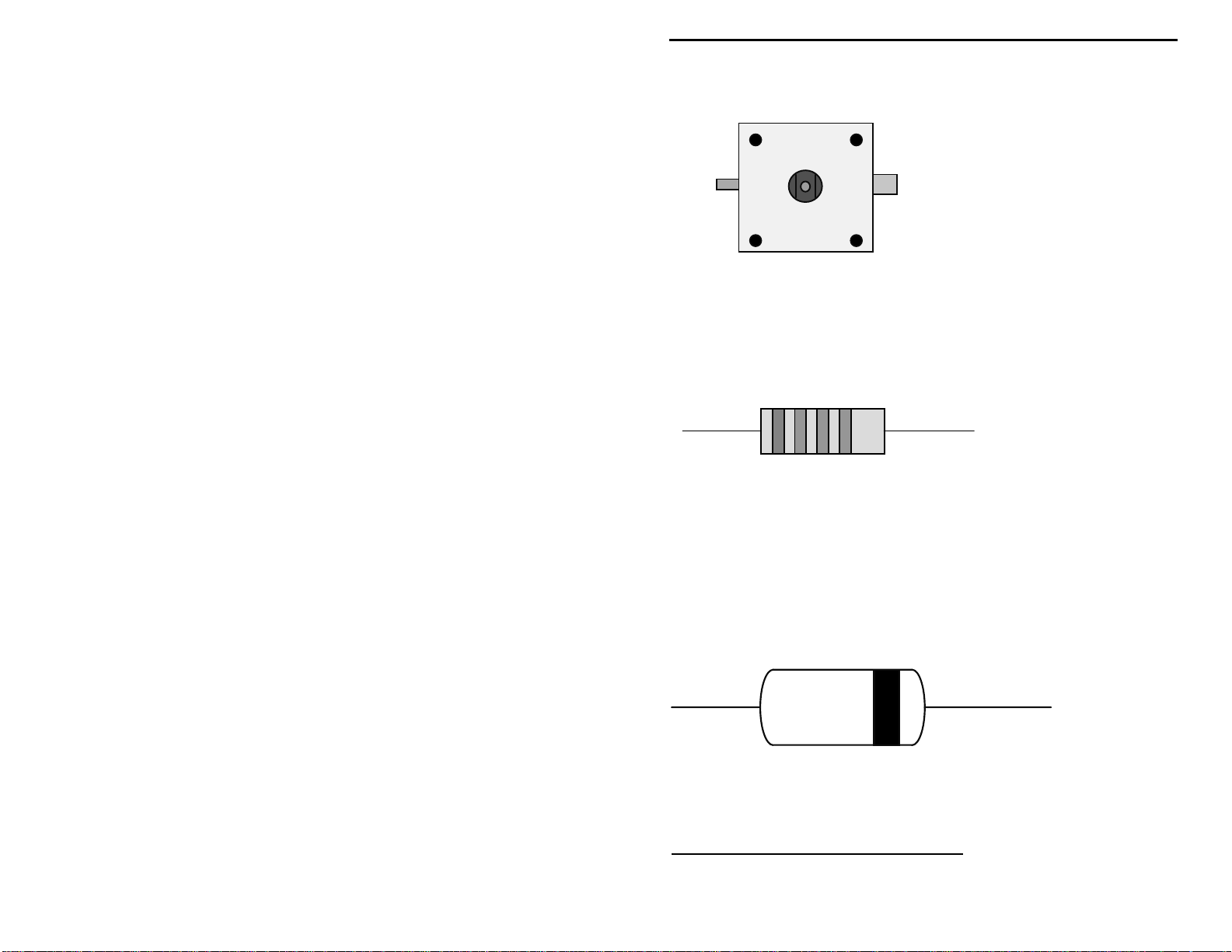
!
1 27K resistor (red-violet-orange-gold)
!
1 1N34A germanium diode
Fahnstock clips
Tuning capacitor.
7
Page 10
VEC-121K Owner's Manual Crystal Radio Set Kit
Resistor:
Germanium diode:
1N34A
STEP-BY-STEP CONSTRUCTION
8
Page 11

VEC-121K Owner's Manual Crystal Radio Set Kit
Before starting any construction, please read the Vectronics warranty. Kits that
have been started cannot be returned for credit. Make sure this kit is within your
skill level before starting assembly!
Phase 1: Breadboard preparation
!
Find the pine board. Look it over carefully, and select which side you wish
to use for mounting the parts. Chose the side that has the fewest
imperfections, and has the nicest looking grain pattern.
!
Locate the drawing that shows the screw hole pattern for the pine board.
!
Place the screw hole pattern guide over the board, be sure the board edges
line up with the outline on the drawing. Use masking tape to hold the
pattern to the board.
!
Using a finishing nail and small hammer, make a small punch mark at each
of the eight screw hole locations. These marks will show you where the
screw holes are located on the board. Don’t drive the nail into wood! We
need only make small indentations, about 1/8”, to mark the screw locations,
and to provide pilot holes for the wood screws.
!
Remove the paper pattern guide.
!
Find one of the eight Phillips head screws and a Phillips head screwdriver.
!
At each of the eight screw hole locations marked by the finishing nail, screw
the Phillips head screw fully into the board, stopping when its head reaches
the board surface. Make sure the screw remains perfectly straight, and not
tilted, when doing each of the eight holes.
!
Return the screw to the parts bag.
!
Find the 5-inch length of PVC pipe. The tuning coil will be wound on this
section of plastic pipe. It is called a coil form.
!
There are six holes drilled through the pipe, look for the two outer, and
larger sized, mounting holes.
9
Page 12

VEC-121K Owner's Manual Crystal Radio Set Kit
Mounting hole
Mounting hole
!
Now, make sure that the two screw pilot holes on the pine board for
mounting the coil form are correct. Refer to the drawings in the manual that
show the placement for the Fahnstock clips and coil form. Temporarily
mount the coil in its proper location using two Phillips head screws. You do
not need to fully tighten the screws, we are just checking to see that things
fit properly.
Important Note:
three inches) for these two screws because of the large diameter of the coil
form.
!
If the coil form mounting holes align properly with the breadboard’s
You will need to use a screwdriver with a long shaft (about
mounting holes, you may remove the coil and return the screws to the parts
bag. If things don’t match up just right, you will have to mark the correct
position for the breadboard pilot hole with a pencil, and remove the coil.
Make a new pilot ho le by using the hammer and finishing nail to make a
small indentation to start the screw. Run a screw into the pilot hole until the
head reaches the board surface. Remove the screw and return it to the parts
bag.
This completes Phase 1. There should be eight screw holes in the pine
breadboard at this point. If so, the mounting holes have been properly located,
marked, and the screw holes are ready for parts installation!
If you haven’t already done so, this is an excellent time to stain the board (if you
are planning to do so).
We are ready to begin Phase 2.
10
Page 13

VEC-121K Owner's Manual Crystal Radio Set Kit
Phase 2: Winding the tuning coil
This portion of the assembly involves winding about 66 turns of 18 AWG
enamel coated copper wire over a 2½” area of the PVC plastic coil form. This
will take time, patience, planning and prac tice! Here are a few suggestions to
help you along.
You will be directed to unwind a length of wire from the 100-foot coil of enamel
wire in several of the following steps. Always unspool the wire, never allow it to
uncoil in Slinky
TM
toy fashion. The unspooled length of wire should be laid out
in a straight line—do not allow it to simply pile onto the floor, or you will end
up with a hopeless tangl e of wire. After unwinding a length of wire, use two
strips of masking tape to secure the remaining wire on the coil.
The winding on the co il should be smoo th and even—with no gap s or kinks. If
the copper wire kinks during handling, smooth it out as best you can before
trying to wind it. We are going to wind a single-layer coil, this is called a
solenoid winding. The winding is done in several steps. You will be instructed
to stop winding a fter a certain amount of wire is wound. If you have a friend
who is willing to help, ask him to give you a hand winding the coil. Four hands
can be very helpful!
!
Remove several 5-inch lengths of masking tape from the roll of tape. Keep
them within arm’s reach while winding the coil.
!
Find the PVC coil form and the 100-foot hank of coil wire.
!
Unspool about 15’ of wire from the 100-foot coil of wire. Leave wire
attached to the spool—do not cut it! Tape the remaining wire so it will not
unwind and become tangled.
!
First, secure the wire at the starting point of the winding. Insert about 16”
of wire into the starting hole, and loop it back out of the adjacent wire hole
and pull tightly. Either end of the form may be used as the starting point.
This will secure the wire. The illustration below shows how to do this:
11
Page 14
VEC-121K Owner's Manual Crystal Radio Set Kit
16” wire tail
!
Tuck the 16” wire tail back inside of the coil form, so it will be out of the
way during winding.
!
Hold the coil form in your left hand. The wire coming from the 100-foot
coil should be between you and the form. Insert the middle and index finger
of your left hand into the coil form. Place your left thumb over the wire at
the starting hole.
!
Use your right hand to help turn the PVC coil form while winding the coil.
This takes a little practice, but you will quickly master the technique once
you st art.
!
Wind several tur ns of wire by tur ning the form. Use your left hand thumb to
guide the wire, a nd keep enough pressure o n the wire with your thumb so
that the windings are tight, even, and spaced together.
!
After several turns are completed, examine your work. (Keep your thumb in
place so the wire doesn’t loosen on the coil form!) The wire windings
should be even and spaced so the wire of each turn is firmly pressed against
the next. The windings sho uld be tight. T here should b e no gaps between
the wire turns. You can squeeze the windings together to remove small
gaps.
!
The first several turns of the winding form the foundation for the rest of the
windings. If you didn’t quite get it right the first time, unwind the coil and
try again.
!
Once you are satisfied with your work, grab a piece of masking tape with
your right hand, and tape acro ss the windings to hold them securely. Note:
Tape across and over the windings—the tape should follow the 5” width of
the coil.
!
Using its dispenser tip, put a small drop of contact adhesive on the winding
at its beginning and end point. Smear any excess back over adjacent
12
Page 15

VEC-121K Owner's Manual Crystal Radio Set Kit
windings using the di spenser ti p. Dr aw a very light b ead of adhe sive ac ross
the full width of the winding. Very little adhesive is needed for these tasks!
Let the coil sit until the contact cement has fully cured! (You may use the
glue sold for assembling plastic models for these tasks. Remember, it will
take several ho urs for the glue to harden.)
!
Now, finish winding the tuning co il. It takes ab out 3 fe et of wire to do four
full turns. It takes about 66 turns of wire to fully wind the coil over the 2.5”
coil span; so you will use about 52 feet of wire for the entire winding. Don’t
bother trying to count turns as you go. A few extra or missing turns will not
affect the performance of the crystal set. What is important is to have the
winding cover the full 2.5” inch span, without gaps.
!
Unspool another 20 feet of 18 AWG enamel coated wire. Remove the
masking tape from the coil form. Continue winding until the 20 feet of wire
is used. Tape the new windings to hold them in place.
!
Again, inspect the new windings you have just c ompleted. Are they tightly
wound, and free of gaps between adjacent windings? Squeeze the newer
windings towards the st arting windings to clo se up any gaps. W hen you’re
satisfied, use masking tape to secure the turns, and then fix the windings in
place using contact cement or model glue.
Important Note:
your left hand fingers will no longer reach inside of the PVC coil form. At this
point, you will need both hands on the form as you work, and you will be using
both thumbs to guide the wire and keep the proper tension.
!
Continue by unspooling 20 foot lengths of wire at time, winding the coil
As you continue adding windings, you will reach a point where
until you reach the "finish" point on the coil form. Securely tape the coil
windings, and glue the new windings in place.
!
At the end of the winding, mark off an additional 16” of wire, and cut the
wire at this point.
!
Insert the 16” inch wire tail into the “finish” wire hole in the PVC coil form.
Bring the wire back out through the adjacent hole and pull with enough
force so the wire i s snug. Secure the end p oint of the winding with a very
small drop of contact cement.
!
Fish the wire end for the starting point of the winding out of the form. Your
coil should now resemble the illustration below:
13
Page 16

VEC-121K Owner's Manual Crystal Radio Set Kit
16” wire tails
!
Rewind any excess wire back onto the supply spool.
Congratulations! You have just wound an inductor that has about 217-uH of
inductance! Put the coil aside for now, you’ll be mounting it on the breadboard
soon.
Phase 3: Mounting the parts
!
Locate the six Fahnstock clips, and six of the eight Phillips screws supplied
with the kit.
!
Refer to the positioning guide below for the following steps.
DET1 DET2
ANT
GND
EAR1
EAR2
In the following several steps, we will mount the six Fahnstock clips.
!
Place a Fahnstock clip at the point shown as GND in the drawing. Align the
clip so its rounded over edge faces the board edge.
!
Secure the clip to the board using one of the Phillips head screws. Tighten
the screw until snug, so it holds the clip firmly. Do not over tighten.
14
Page 17

VEC-121K Owner's Manual Crystal Radio Set Kit
For the remaining steps, align the Fashnstock clips as shown in the drawing.
!
Mount a second clip at the ANT position on the breadboard using a Phillips
screw.
!
Mount a clip using a Phillips screw at the DET1 position on the breadboard.
!
Mount a clip using a Phillips screw at the DET2 position on the breadboard.
!
Mount a clip using a Phillips screw at the EAR2 position on the breadboard.
!
Mount a clip using a Phillips screw at the EAR1 position on the breadboard.
The six Fahnstock clips should all be mounted at this point.
!
Find the coil and the remaining two Phillips head screws.
!
Mount the coil to the board using the two Phillips head mounting screws.
Before tightening the screws, make sure the two 16” coil lead wires are
oriented towards the front of the breadboard. You may now tighten the
screws so the coil is mounted snugly against the board. NOTE: Over-
tightening the screws may damage the coil form, or cause the screws to
strip the pine board.
Your crystal receiver should resemble the following drawing:
You have finished Phase 3 of your crystal set receiver project. In Phase 4, we'll
be doing the wiring between the crystal set’s components.
Phase 4: Wiring the crystal set
In phase 4, most of the wiring will involve using the two 16” coil wires. For
clarity, we are only showing the components we are going to be working with.
15
Page 18

VEC-121K Owner's Manual Crystal Radio Set Kit
You need to know where the wire leads need to be sanded to make connections.
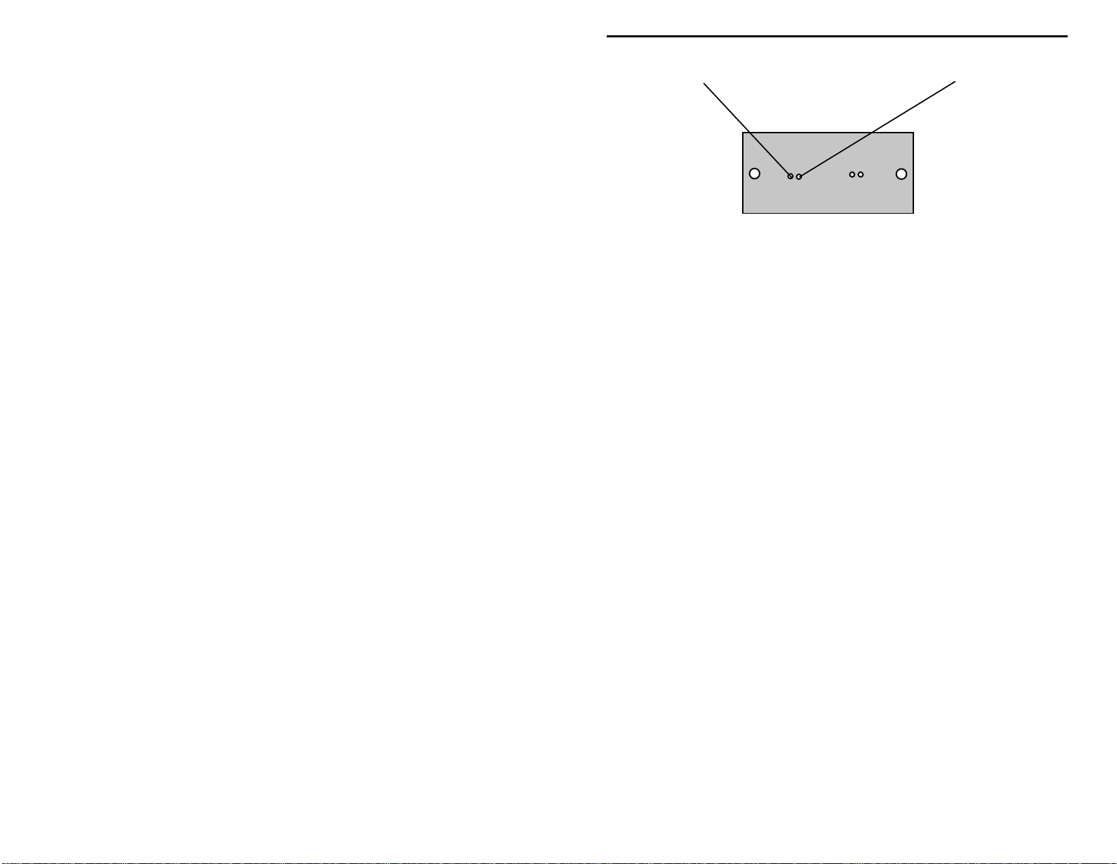
Route the coil wire, as shown in the following diagram, by loosening the Phillips
screws mounting the two Fahnstock clips labeled ANT and DET1 (as shown):
3.5”
2.5”
!
Measure and mark the coil wire lead at the left-hand side of the crystal set at
3.5 inches. The measurement is taken from the point where the wire exits
the form.
!
Remove about 1” of insulation at the 3.5” mark.
!
Form the wire so the area stripped of insulation forms a through connection.
!
Loosen the Phillips head screw for the ANT Fahnstock clip.
!
Route the through-connection loop so it passes between the ANT Fahnstock
clip and breadboard.
!
Tighten the ANT clip mounting screw so it is snug.
!
Measure and mark the wire lead emerging from the antenna clip at 2.5”.
!
At the 2.5” point, remove 1” of wire insulation, and form a second through-
connection half loop.
!
Loosen the Phillips screw mounting the DET1 Fahnstock clip.
!
Route the second through connection so it passes under the DET1
Fahnstock, loops around the screw shank, and exits as shown in the
drawings.
!
Tighten the Phillips screw for the DET1 clip so it is snug.
!
Several inches of wire should remain from the DET1 clip connection, this
will be used later.
In the next few steps you will be working with the right-hand coil wire. Refer to
the drawing below for the following steps:
16
Do not cut the wire until told to do so!
Page 19

VEC-121K Owner's Manual Crystal Radio Set Kit
5”
5.5”
GND EAR2
Important Note:
!
Mark the left-hand coil wire at 5” from where it exits the coil.
!
At the 5” point, remove 1” of insulation from the wire.
!
Form the area stripped of insulation into a through-connection half loop.
!
Loosen the Fahnstock clip mounting screw for the EAR2 clip.
!
Pass the through-connection between the EAR2 clip and breadboard, with
The “dotted” lines show wiring done in previous steps.
loop going around the Phillips screw shank, as shown above.
!
Tight en the mounting screw for the EAR2 c lip until snug.
!
Measure the wire exiting from the EAR2 connection, and at the 5.5” point
remove 1” of insulation from the wire.
!
Form the area of wire stripped of insulation into a second through-
connection half loop.
!
Loosen the Phillips screw that mounts the Fahnstock clip used for the GND
connection.
!
Pass the through-connection between the GND clip and breadboard, with
the loop going around the Phillips screw shank, as shown above.
!
Tighten the GND P hillips mounting screw until snug.
!
Several inches of wire should remain from the GND connection.
Do not cut
this wire until instructed to do so!
This completes Phase 4. You’ve come a long way since first opening the kit.
Your little crystal receiving set is really starting to look like something.
Phase 5: Final wiring
17
Page 20

VEC-121K Owner's Manual Crystal Radio Set Kit
Only a few more steps remain, and the set will be finished.
Refer to the drawing below for the last wiring steps.
EAR1
DET2
!
Cut a 4½” length of 18 AWG enamel wire from the wire spool in the kit.
!
Remove 1” of insulation from each end.
!
Form each end of the wire into an end connection.
!
Loosen the screws mounting the Fahnstock clips DET2 and EAR1.
!
Take one of the wire end connections and place between the DET2 clip and
breadboard.
!
Tighten the mounting sc rew for the DET2 clip until snug.
!
The remaining end connection is placed between the EAR1 clip and
breadboard.
!
Tighten the mounting sc rew for clip EAR1 until snug.
18
Page 21

VEC-121K Owner's Manual Crystal Radio Set Kit
!
The wire should be routed so it crosses over the wire from the right end of
the coil without the wires touching each other.
!
Find the 27K ohm resistor (it has the Red-Violet-Orange-Gold colored
bands) and form the leads as shown below:
Important Note:
connection.
It makes no difference which lead is used for either
!
The ends of the resistor leads are formed into little half loop hooks.
!
Loosen the two Phillips screws for EAR1 and EAR2 clips.
!
Put one of the half loop connections between the top of the clip body, and
the bottom of the screw head for the EAR1 clip. Adjust the size of the loop
so it fits snugly around t he shank of the screw.
!
Tighten the mounting screw for clip EAR1 until snug. The resistor lead
should remain firmly attached.
!
Place the remaining loop between the screw head and body of the clip
EAR2. Re-form the loop so it fits snugly around the screw body.
!
Tighten the screw for clip EAR2 until snug. The resistor lead should remain
firmly attached.
!
Find the germanium detector diode. Form the leads as shown below.
19
Page 22

VEC-121K Owner's Manual Crystal Radio Set Kit
!
A 3/8” length of each of the diode’s lead ends is sharply folded back on
itself. This is done because the diode will be mounted in the DET1 and
DET2 Fahnstock clips. The diode lead wires are a very small diameter, and
may not be held tightly enough b y the clip unless the leads ar e made a bit
thicker.
!
Follow the diagram below, and clip the diode's anode lead into the DET1
Fahnstock clip, and the cathode lead (the lead with the band close to it) into
the DET2 Fahnstock clip. Gently pressing down on the clip opens the jaw,
permitting the wire lead to be inserted.
Find the tuning capacitor. Refer to the drawing below for the following steps.
20
Page 23

VEC-121K Owner's Manual Crystal Radio Set Kit
Stator
stud
Rotor lug
(narrow)
This is the correct orientation for installing the capacitor. Note that the
narrower rotor lug must be at the left hand side!
Variable capacitors have two sets of plates. One set of plates remain stationary,
and are called the “stator” plates. The tuning shaft is attached to another set of
plates that rotate as the shaft is turned. They are called the “rotor” plates. As
the shaft is turned, the plates are either meshed or unmeshed, changing the
capacitance value. This is how the tuning capacitor works.
The tuning capacitor will be mounted at the front center of the breadboard using
the double-sided foam tape. The remaining enamel wire lead coming from the
GND Fahnstock clip will be connected to the narrow rotor lug terminal on the
tuning capacitor. The remaining enamel wire lead from the DET1 Fahnstock
clip will be connected to the round stator stud on the front of the capacitor.
The above drawing shows how the wires will be routed to the tuning capacitor
connections.
Connecting the stator lead
21
Page 24
VEC-121K Owner's Manual Crystal Radio Set Kit
!
Temporarily place the tuning capacitor as shown in the drawing.
Be sure the
narrowest stator lug is at the left hand side!
!
Cut the free enamel wire lead from the GND clip to a length of five inches.
!
At the end of the wire, remove 2” of insulation.
!
Route the enamel wire from the GND clip so it reaches to the capacitor
body. At that point, the wire goes up to the middle of the capacitor, and
then makes another sharp bend towards the front of the board.
Study how the capacit or i s made. I f you loo k into the cap acito r thr ough it s clea r
plastic housing, you ca n see ho w the nar r ow ro to r l ug co nti nues t o t he r ea r o f the
capacitor. At that point, there is a tiny opening in the plastic capacitor housing.
!
Take the wire from the GND clip and insert it into this capacitor opening.
Carefully feed the wire so it passes through the ca pacitor body (it will be
between the plastic housing and narrow metal strap) and finally emerges at
the front end of the capacitor.
!
Continue feeding the wire until 1” of bare enamel wire clears the front
opening in the capacitor.
!
Using your long nose pliers, carefully wrap the enamel wire around the
narrow rotor lug until two or three full turns are made. Trim off the excess
wire.
!
Gently, but firmly, squeeze the turns wrapped around the rotor lug, using the
long nose pliers, until they are compressed tightly--making a good, tight
electrical connection.
Important Note:
to attach the lead, use the wider rotor lug as an alternate connection point.
If for some reason the narrow rotor lug is damaged while trying
Making the stator connection
22
Page 25

VEC-121K Owner's Manual Crystal Radio Set Kit
!
Temporarily place the capacitor at its mounting location.
!
Route the free enamel wire coming from the DET1 Fahnstock clip so it
follows the breadboard, and comes up and over the top of the capacitor until
it reaches the stator stud. (Refer to the drawings to identify the proper stud.)
!
Trim the wire coming from the DET1 clip to a length of 4½”.
!
Remove 1½” of insulation from the wire end.
!
Wind the wire over the stud to form three tightly wound turns. See the
following drawing. Use e nough wire so when finished you have a small ½”
pigtail remaining.
!
You need a good, tight electrical connection. Slide the turns off of the
stud—note how they make a little coil. Gently tighten the coil by twisting
the coil so it is smaller.
!
The coil should slide back on with some difficulty—otherwise the turns are
to loose.
!
To make an even tighter connection, take the pigtail, and wrap it back over
the wire in a half-loop.
23
Page 26

VEC-121K Owner's Manual Crystal Radio Set Kit
!
Using the long nose pliers, gently twist the half loop to take up wire slack
and tighten the wire wraps made over the stud.
Important Note:
directly beneath it may be used as a backup. The two right hand studs may not
be used.
!
Place the capacitor at its mounting location at the center front of the board.
If the stator stud is damaged beyond use, the stud located
The body of the capacitor should sit about 1/8” back from the board edge.
Use a ruler to center the capacitor body at 3” from either outside board
edge.
!
Mark the capacitor body outline by tracing its outline onto the breadboard
with a pencil.
!
Find the double-sided foam tape.
!
Remove one of the protective covers from one side of the tape. Place the
sticky side over the capacitor outline on the breadboard. Firmly press the
tape to set the adhesive.
!
Remove the protective cover over the top of the tape.
!
While being careful to keep the capacitor centered on the board, and parallel
to the front edge of the board, pr ess it to the foam tape. Apply gentle, but
firm, pressure to set the adhesive.
!
Find the ¼” diameter aluminum tuning shaft extension. Align the threaded
screw end with the opening in the capacitor tuning shaft. Screw the
extension into the tuning capacitor.
!
Unscrew the tuning shaft about 1 or 2 turns, to open a gap between the two
shafts.
24
Page 27

VEC-121K Owner's Manual Crystal Radio Set Kit
!
Using the dispenser, allow a small drop of contact adhesive to flow into the
gap and onto the threaded portion of the extension. Quickly screw the
extension back into the tuning capacitor to close the gap. If you are using
model airplane cement, unscrew the shaft extension, and lightly smear a
small amount of glue over the threads. Quickly screw the extension back
into the capacitor shaft.
!
Allow time for the glue to harden.
!
Using a small screwdriver or hex tool , install the tuning knob on the shaft
extension.
This completes the construction of the VEC-121K crystal set receiver.
TESTING AND ALIGNMENT
1. Turn the capacitor shaft in a counter clockwise direction until the stop is
reached.
2. Loosen the tuning knob set screw, and a lign the tuning indicato r on the knob
so it corresponds to the 9 o’clock position.
3. Tighten the set screw.
4. Verify that the knob indicator properly corresponds to the capacitor stops at
the 9 and 3 o’clock positions.
OPERATING INSTRUCTIONS
1. Use the hookup shown in the following diagram to make the antenna (aerial),
ground, and earphone connections.
aerial
earphone
Tuning k n ob
ground
2. Connect the earphone wires to the Fahnstock clips at the right hand side of
the radio.
25
Page 28
VEC-121K Owner's Manual Crystal Radio Set Kit
3. Connect a good ground connection to the crystal receiver. Use the 7 foot
length of stranded hookup wire supplied with the kit to make the ground
connection between a good earth ground and the Fahnstock clip on the
receiver.
4. Connect a long wire antenna to the Fahnstock clip on the receiver.
5. Carefully tune the tuning knob while listening for signals in the earphone.
You should be able to copy at least one, and maybe several, stations without
difficulty.
What can I hear?
difficulty. The crystal set tunes the entire broadcast band from 530 kHz to 1700
kHz. The antenna and ground system are the keys to success when using crystal
sets. Where you live affects how well you receive signals. If you live in a salt
marsh, or along the shore, you may experience exceptional reception. The
fellow living in an arid area with poor soil moisture may have much poorer
reception.
When to listen?
radio signals propagate over greater distances. Listening just before the sun goes
down may yield some pleasant surprises! Also, as the seasons change, you may
find you can hear different distant stations at sundown. Keep a simple log of
new stations when you receive them. Note the time, call letters and frequency.
It’s always fun to add a “new one” to the list.
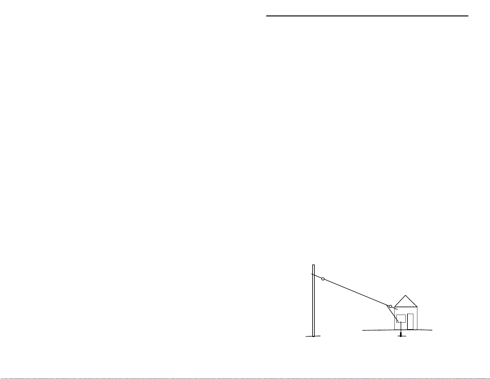
Erecting a good antenna
Your radio will work only as good as the antenna and ground it is connected to
do. The best antenna for a crystal set is located outdoors, it is between 100 and
30 feet long, and is mounted high and in the clear. Your kit inc ludes enough
wire to make an outdoor 40 foot wire antenna and short lead-in wire to the
crystal set receiver.
You should be able to hear local stations without much
You should hear local stations at any time of the day. At dusk,
26
Page 29

VEC-121K Owner's Manual Crystal Radio Set Kit
This diagram shows an aerial going between a pole (or tall tree trunk) and
location where the receiver is located. A small length of lead-wire connects the
antenna to the crystal set inside of the house. (Make sure the lead-in wire makes
good electrical connection to the antenna wire!) Note the insulators between the
antenna wire and the supporting structures. A good earth ground is provided by
a short ground rod driven into the earth outside of the window where the crystal
set is located. You may make your own insulators from scraps of 1” plastic pipe,
or small sections of 1” by 6” Lexan
TM
or PlexiglasTM . Drill holes at the ends of
the insulators for tie-points for the antenna wire and support rope. Clothesline is
a good way to tie the insulator to the supporting structures.
The antenna wire should not be allowed to touch leaves or rub against branches.
Doing so will affect your reception. Keep your antenna wire away from power
lines.
Finding the elusive ground
Several feet of insulated stranded hookup wire is included in your kit. This is
provided to connect a ground to the crystal set. But, what is a good ground and
how can you make or find o ne?
Ground rods
. Many times a crystal set will work quite well without a ground
connection, especially if a very good antenna is being used. The most effective
ground is a 10 foot ground rod dr iven into the ea rth. If you have a TV antenna
on your home, it should be connected to a gro und rod for li ghtning protecti on. If
it is near your operating position, you may be able to tie a wire between your
crystal set a nd the TV a ntenna ground rod. Even four or five fe et length of ol d
copper pipe driven into the earth will do in a pinch! But, be sure you use some
sandpaper to remove any corrosion on the pipe that would prevent making a
good electrical connection to your ground wire lead in.
Water pipe grounds.
If you live in an older home that uses metal instead of
plastic plumbing, you have a good ground point at the nearest water pipe or
radiator. Connect a short wire between the crystal set ground and the water pipe.
Remember that the pipe must be free of corrosion or paint to make a good
electrical connection.
Counterpoise grounds.
The reason the crystal set needs a ground is because a
single wire antenna is really only one-half of a complete antenna! The ground
makes up for the missing half of the antenna, and gives the wire antenna
something to “work against”. If you have 50 or 60 feet of scrap wire laying
about, you can make what is called a “counterpoise” to serve as a ground for the
crystal set. Simply run the wire out on the ground in a straight line. The wire
needn’t be buried, it will “couple” to the earth due to “stray capacitance”.
Connect one end of the counterpoise wire to the ground Fahnstock on the crystal
set, and you’re in business!
27
Page 30

VEC-121K Owner's Manual Crystal Radio Set Kit
IN CASE OF DIFFICULTY
This crystal set almost has to work, if it was built according to the directions. If
you can not hear any stations at all, go back over the assembly instructions and
try to find any erro rs that you might have made during constructi on. Perhaps
you missed removing the insulation from the wire at a connection. Or, a wire is
in the wrong place. Have a friend check your work. It’s very easy to look over a
mistake, and a fresh pair of eyes will often quickly find mistakes that elude your
detection. Factory repair is available for assembled kits that do not work.
Consult the warranty for information regarding factory service.
Here’s a quick check list of common problems.
The set receives several signals at once.
don’t have the ability to separate signals that very are strong or close in
frequency.
The tuning control has no effect.
capacitor are tight, and that the proper connection points to the tuning capacitor
were used.
Signals are very weak, or I can only hear one station.
normal, if there are no strong signals in your area. Check your ground and
antenna connect ions. A longer antenna or better ground may improve things.
Set works intermittently
Fahnstock clips are making good connections to the antenna, ground and
earphone wires. If a clip won’t grip the wire properly, remove the wire and bend
the clip upwards slightly. This should restore the clasping action of the clip’s
jaw.
There is a local station at the high or low end of the dial that I can’t hear.
The VEC-121K is designed to tune the entire broadcast band. However, there
will be certain antenna lengths that will behave in unexpected manners at certain
frequencies. Also, because of the way the antenna and ground are coupled to the
receiver tuned circuits, they will also have some effect on the tuning range limits.
. This sounds like a poor connection. Check that the
This is normal for crystal sets. They
Check that the connections to the tuning
Again, this may be
THEORY OF OPERATION AND SPECIFICATIONS
The tuning capacitor and coil form a parallel resonant circuit that tunes from
about 530-kHz to over 1.6 MHz. The antenna and ground are directly applied
across the resonant circuit. Thus, the set is optimized for use with short, high-
28
Page 31

 Loading...