

Page 1

IMPORTANT WARRANTY INFORMATION! PLEASE READ
Return Policy on Kits When Not Purchased Directly From Vectronics: Before continuing
any further with your VEC kit check with your Dealer about their return policy. If your Dealer
allows returns, your kit must be returned before you begin construction.
Return Policy on Kits When Purchased Directly From Vectronics: Your VEC kit may be
returned to the factory in its pre-assembled condition only. The reason for this stipulation is,
once you begin i nsta lli ng a nd sol deri ng pa rt s, you essenti al ly tak e over the rol e of the devic e's
manufacturer . From this point on, neither Vect ronics nor its dea lers can reas onably be held
accountab le for the qua lity or the outcome of your work. Because of this, Vectronics cannot
accept return of any kit-in-progress or completed work as a warranty item for any reason
whatsoever. If you are a new or inexperienced kit b uilder, we urge you to read the manual
carefully a nd determine whether or not you're r eady to tak e on the job. If you wish to c hange
your mind and return your ki t, you may--b ut you must do i t before you begin c ons tr uc ti on, a nd
within ten (10) working days of the time it arrives.
Vectronics Warrants: Your kit contains each item specified in the parts list.
Missing Parts: If you determine, during your pre-construction inventory, that any part is
missing, please contact Vectronics and we'll send the missing item to you free of charge.
However, before you contact Vect ronic s, please look carefully to c onf ir m you haven't misr ea d
the marking on one of the other items provided with the kit. Also, make certain an alternative
part hasn't been substituted for the item you're missing. If a specific part is no longer
available, or if Engineering has determined that an alternative component is more suitable,
Vectronics reserves the right to make substitutions at any time. In most cases, these changes
will be clearly noted in an addendum to the manual.
Defective Parts: Today's electronic parts are physically and electrically resilient, and
defective components a re r a re. However, if you disc over a n it em duri ng your pr e- c onst r uct i on
inventory that's obviously broken or unserviceable, we'll replace it. Just return the part to
Vectronics at the address below accompanied with an explanation. Upon receipt, we'll test it.
If it's defec tive and appear s unused, we'll ship you a new one right away at no charge.
Missing or Defective Parts After You Begin Assembly: Parts and materials lost or
damaged after construction begins are not covered under the terms of this warranty. However,
most parts supplied with VEC kits are relatively inexpensive and Vectronics can replace them
for a reasonable charge. Simply contact the factory with a complete description. We'll
process your order quickly and get you back on trac k.
Factory Repair After You Begin Assembly: Kits-in progress and completed kits are
specifically excluded from coverage by the Vectronics warranty. However, as a service to
customers, tec hnicia ns ar e availa ble t o evaluate a nd repai r malf unctioni ng kits for a minimum
service fee of $18.00 (½ hour rate) plus $7.00 shipping and handling (prices subject to
change). To qualify for repair service, your kit must be fully completed, unmodified, and the
printed circuit board assembled using rosin-core solder. In the event your repair will require
more than an hour to fi x (or $36.00, subject to change), our technicians will contact you in
advance by telephone b efore p erforming t he work. Def ective unit s should b e shipp ed prep aid
to:
Vectronics
1007 HWY 25 South
Starkville, MS 39759
Page 2

When shipping, pack your kit well and include the minimum payment plus shipping and
handling charges ($25.00 total). No work can be performed without pre-payment. Also,
provide a valid UPS return address a nd a day time phone number where you may be reac hed.
Page 3

VEC-1120K/1130K/1140K/1180K Instruction Manual
INTRODUCTION
Whether you’re a novice or seasoned “pro”, you’ll be pleasantly surprised at
how these receivers perform! SSB, CW and AM signals from hams around the
world are easily copied; their sensitivity rivals those receivers that cost many
times more. Build the receiver for your favorite band. Eight tuning options
allow you to customize the tuning range from full-band to 100-kHz or less. Use
it on-the-go or at home with your home-brew or Vectronics QRP CW transmitter
kit. Powered by a common 9-volt transistor battery, it’s always ready for action
on Field Day or camping trips!
TOOLS AND SUPPLIES
Construction Area:
area where you can easily organize and handle small parts without losing them.
An inexpensive sheet of white poster board makes an excellent construction
surface and provides protection for the underlying table or desk. Well-diffused
overhead lighting is a plus, and a supplemental high-intensity desk lamp is
especially helpful for close-up work. Safety is always important! Be sure to use
a suitable high-temperature stand for your soldering iron, and keep the work area
free of combustible clutter.
Universal Kit-building Tools:
additional items for completion, virtually all construction projects require a work
area outfitted with the following tools and supplies:
!
30 to 60 Watt Soldering Iron (grounded-tip and temperature-controlled
preferred)
!
High-temperature Iron Holder with Cleaning Sponge
!
Rosin-core Solder (thin wire size preferred, .031”)
!
Needle Nose Pliers or Surgical Hemostats
!
Diagonal Cutters or “Nippy Cutters”
!
Solder Sucker (squeeze or vacuum pump type), or Desoldering Braid
!
Bright Desk Lamp
!
Magnifying Glass
Special Tools for This Kit:
!
"Hex” tuning to ol
!
“Blade” type tuning tool or jeweler’s screwdriver
Kit construction requires a clean, smooth, and well-lighted
Although your particular kit may require
1
Page 4

VEC-1120K/1130K/1140K/1180K Instruction Manual
BEFORE YOU START BUILDING:
Experience shows there are four common mistakes builders make. Avoid these,
and your kit will probably work on the first try! Here's what they are:
1. Installing the Wrong Part:
1K and a 10K resistor may look almost the same, but they may act very
differently in an electronic circuit! Same for capacitors--a device marked
102 (or .001 uF) may have very different operating characteristics from one
marked 103 (or .01uF).
2. Installing Parts Backwards:
capacitors to make sure the positive (+) lead goes in the (+) hole on the
circuit board. Transistors have a flat side or emitter tab to help you identify
the correct mounting position. ICs have a notch or dot at one end indicating
the correct direction of insertion. Diodes have a banded end indicating
correct polarity. Always double-check--especially before applying power to
the circuit!
3. Faulty Solder Connections:
bridges. Cold solder joints happen when you don't fully heat the connection-or when metallic corrosion and oxide contaminate a component lead or pad.
Solder bridges form when a trail of excess solder shorts pads or tracks
together (see Soldering Tips below).
4. Omitting or Misreading a Part:
Always double-check to make sure you completed each step in an assembly
sequence.
Soldering Tips:
Cleanliness and good heat distribution are the two secrets of professional
soldering. Before you install and solder each part, inspect leads or pins for
oxidation. If the metal surface is dull, sand with fine emery paper until shiny.
Also, clean the oxidation and excess solder from the soldering iron tip to ensure
maximum heat transfer. Also, clean the oxidation and excess solder from the
soldering iron tip to ensure maximum heat transfer. Allow the tip of your iron to
contact both the lead and pad for about one second (count "one-thousand-one")
before feeding solder to the connectio n. Surfaces must become hot enough for
solder to flow smoothly. Feed solder to the opposite side of the lead from your
iron tip--solder will wick around the lead toward the tip, wetting all exposed
surfaces. Apply solder sparingly, and do not touch solder directly to the hot iron
tip to promote rapid melting.
It always pays to double-check each step. A
Always check the polarity of electrolytic
Inspect for cold solder joints and solder
This is easier to do than you might think!
Desoldering Tips:
2
Page 5
VEC-1120K/1130K/1140K/1180K Instruction Manual
If you make a mistake and need to remove a part, follow these instructions
carefully! First, grasp the component with a pair of hemostats or needle-nose
pliers. Heat the pad beneath the lead you intend to extract, and pull gently. The
lead should come out. Repeat for the other lead. Solder may fill in behind the
lead as you extract it--especially if you are working on a double-sided board with
plate-through ho les. Should this happen, try heating the p ad again and inserting
a common pin into the hole. Solder won't stick to the pin's chromium plating.
When the pad cools, remove the pin and insert the correct component. For ICs
or multi-pin parts, use desoldering braid to remove excess solder before
attempting to extract the part. Alternatively, a low-cost vacuum-bulb or springloaded solder sucker may be used. Parts damaged or severely overheated during
extraction should be replaced rather than reinstalled.
Work Habits:
Kit construction requires the ability to follow detailed instructions and, in many
cases, to perform new and unfamiliar tasks. To avoid making needless mistakes,
work for short periods when you're fresh and alert. Recreational construction
projects are more informative and more fun when you take your time. Enjoy!
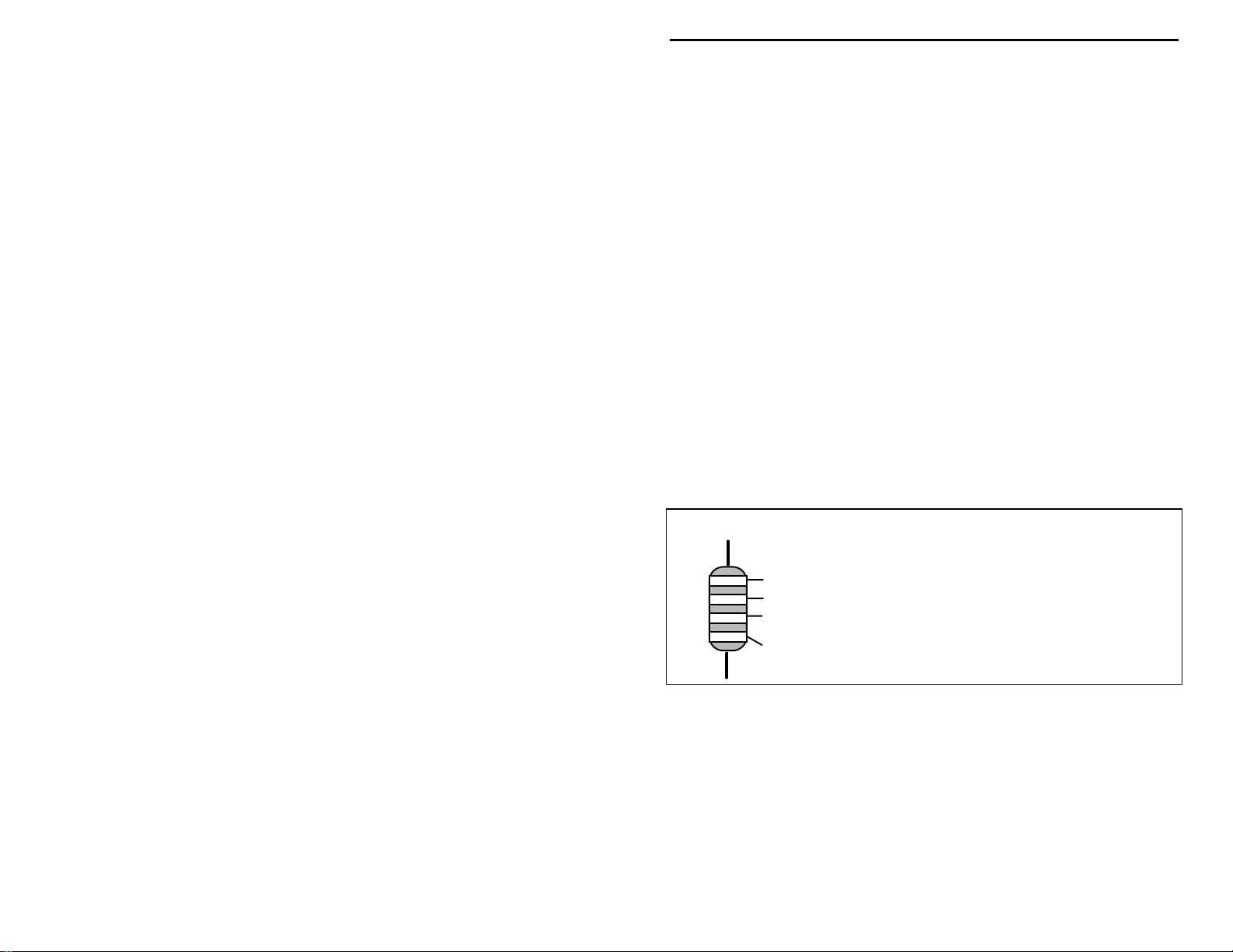
Sorting and Reading Resistors:
The electrical value of resistors is indicated by a color code (shown below). You
don't have to memorize this code to work with resistors, but you do need to
understand how it works:
Resistor Color Code
Black = 0 (tens)
1st Digit
2nd Digit
Multiplier
Tolerence
(gold or silver)
When you look at a resistor, check its multiplier code first. Any resistor with a
black multiplier band falls between 10 and 99 ohms in value. Brown designates
a value between 100 and 999 ohms. Red indicates a value from 1000 to 9999
ohms, which is also expressed as 1.0K to 9.9K. An orange multiplier band
designates 10K to 99K, etc. To sort and inventory resistors, first separate them
into groups by multiplier band (make a pile of 10s, 100s, Ks, 10Ks, etc.). Next,
sort each group by specific value (1K, 2.2K, 4.7K, etc.). This procedure makes
the inventory easier, and also makes locating specific parts more convenient later
Brown = 1 (hundreds)
Red = 2 (K)
Orange = 3 (10K)
Yellow = 4 (100K)
Green = 5 (1Meg)
Blue = 6
Violet = 7
Gray = 8
White = 9
Silver = 10%
Gold = 5%
3
Page 6
VEC-1120K/1130K/1140K/1180K Instruction Manual
on during construction. Some builders find it especially helpful to arrange
resistors in ascending order along a strip of double-sided tape.
Some VEC kits may contain molded chokes which appear, at first glance, similar
to resistors in both shape and band marking. However, a closer look will enable
you to differentiate between the two--chokes are generally larger in diameter and
fatter at the ends than resistors. When doing your inventory, separate out any
chokes and consult the parts list for specific color-code information.
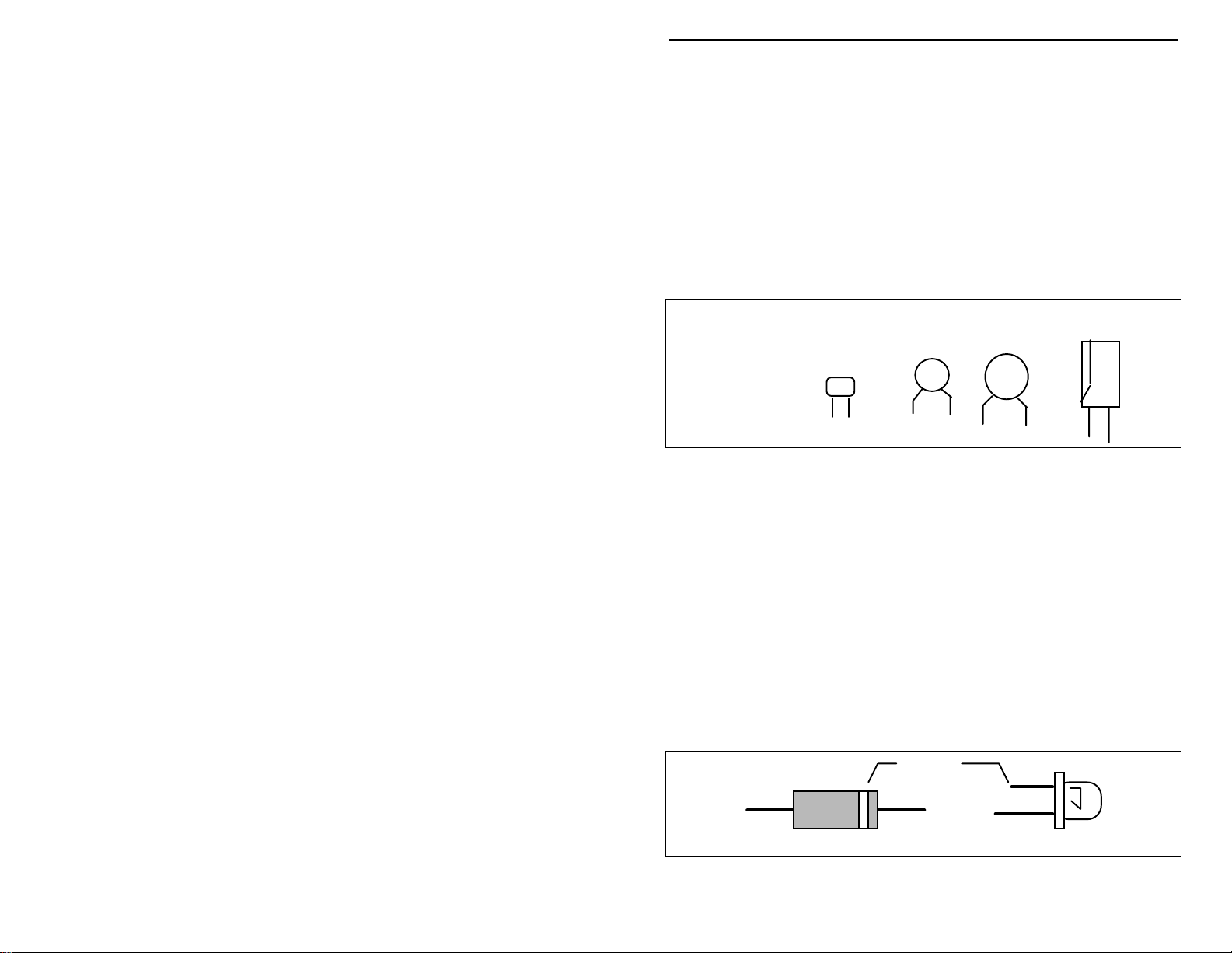
Reading Capacitors:
Unlike resistors, capacitors no longer use a color code for value identification.
Instead, the value, or a 3-number code, is printed on the body.
Value Code
10 pF = 100
100 pF = 101
1000 pF = 102
.001 uF = 102*
.01 uF = 103
.1 uF = 104
As with resistors, it's helpful to sort capacitors by type, and then to arrange them
in ascending order of value. Small-value capacitors are characterized in pF (or
pico-Farads), while larger values are labeled in uF (or micro-Farads). The
transition from pF to uF occurs at 1000 pF (or .001 uF)*. Today, most
monolithic and disc-ceramic capacitors are marked with a three-number code.
The first two digits indicate a numerical value, while the last digit indicates a
multiplier (same as resistors).
Electrolytic capacitors are always marked in uF. Electrolytics are polarized
devices and must be oriented correctly during installation. If you become
confused by markings on the case, remember the uncut negative lead is slightly
shorter than the positive lead.
Diodes:
Diodes are also polarized devices that must be installed correctly. Always look
for the banded or cathode end when installing, and follow instructions carefully.
Multilayer
(270 pF)
271
Ceramic Discs
(.001 uF) (.1 uF)
102
104
Electrolytic
1 uF
1uF
|
35V
|
+
-
Cathode
(shorter Lead)
Diode
4
LED
Page 7
VEC-1120K/1130K/1140K/1180K Instruction Manual
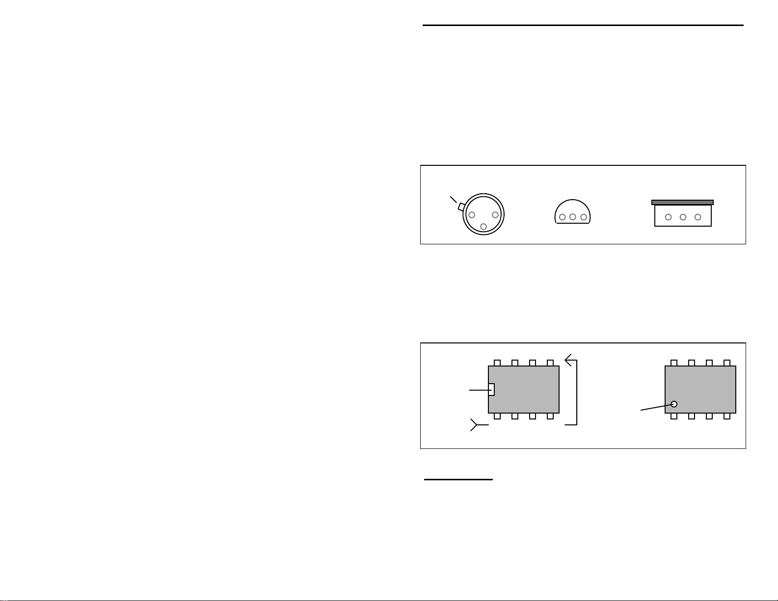
Transistors:
If transistors are installed incorrectly, damage may result when power is applied.
Transistors in metal cases have a small tab near the emitter lead to identify
correct positioning. Semiconductors housed in small plastic cases (TO-92) have
an easily-identified flat side to identify mounting orientation. Many specialized
diodes and low-current voltage regulators also use this type packaging. Larger
plastic transistors and voltage regulators use a case backed with a prominent
metal tab to dissipate heat (T-220). Here orientation is indicated by the
positioning of the cooling tab.
Metal Can Device Plastic Device Tab-cooled Device
Emitter
Flat Side
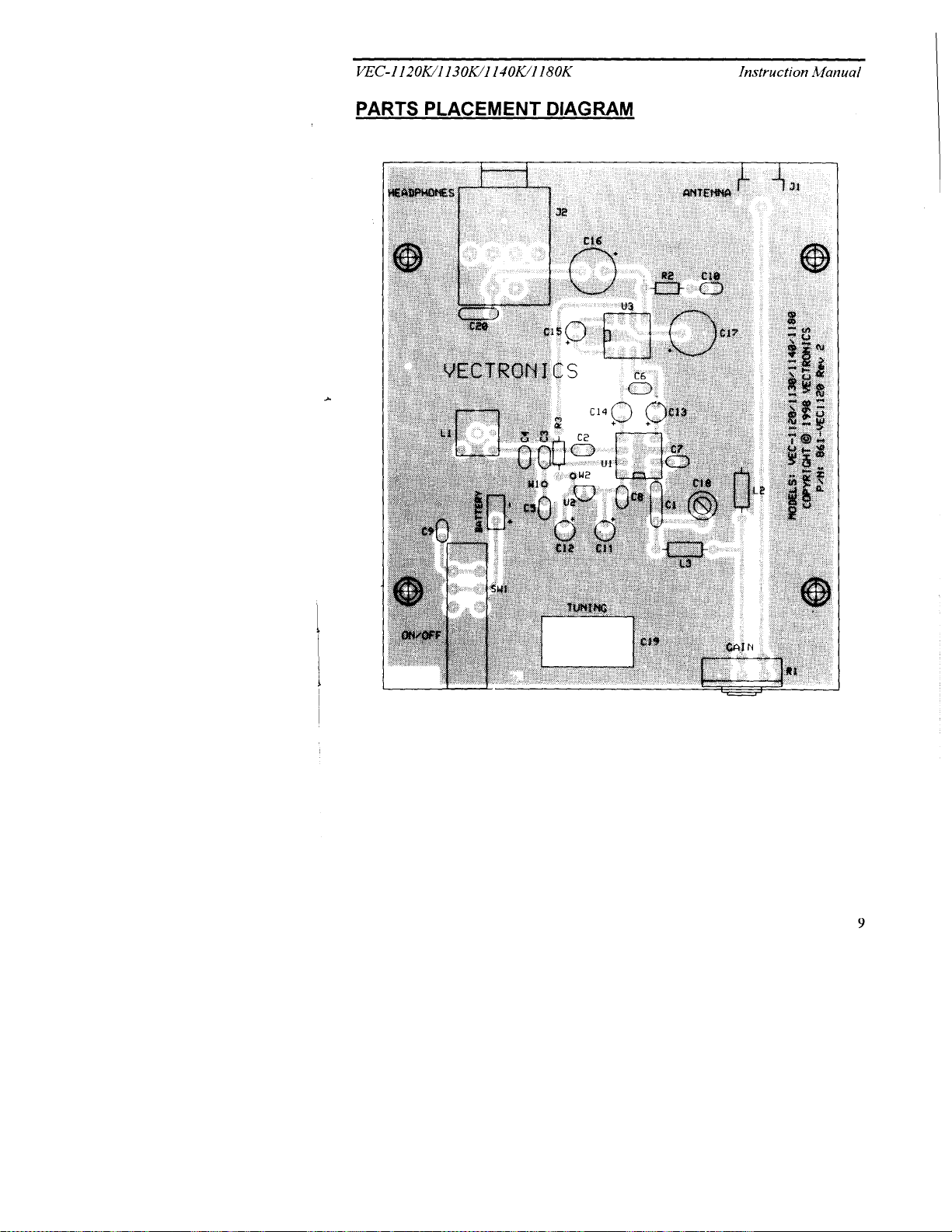
Integrated Circuits:
Proper IC positioning is indicated by a dot or square marking located on one end
of the device. A corresponding mark will be silk-screened on the PC board and
printed on the kit's parts-placement diagram. To identify specific IC pin
numbers for testing purposes, see the diagram below. Pin numbers always start
at the keyed end of the case and progress counter-clockwise around the device,
as shown in the following diagram.
8 7 6 5
Installation
Key
Installation
Key
1 2 3 4
Pin Numbers
Metal Tab
PARTS LIST
Your kit should contain all of the parts listed below. Please identify and
inventory each item on the checklist before you start building. If any parts are
missing or damaged, refer to the manual’s warranty section for replacement
instructions. If you can’t positively identify an unfamiliar item on the basis of
the information given, set it aside until all other items are checked off. You may
5
Page 8

VEC-1120K/1130K/1140K/1180K Instruction Manual
then be able to identify it by process of elimination. Finally, your kit will go
together more smoothly if parts are organized by type and arranged by value
ahead of time. Use this inventory as an opportunity to sort and arrange parts so
you can identify and find them quickly.
T here should be three parts bags in your kit. Two bags contain parts that
Note
:
are common to all of the direct conversion kits. The third parts bag
contains those components that are unique to the VEC-1180, VEC-1140,
VEC-1130 and VEC-1120. Please proceed to the model number heading
that corresponds to your kit and inventory those parts. Note: only the first
three color bands are given for the molded chokes. The fourth band is
the tolerance band, and may be either gold or silver. The following parts
are packaged separately:
VEC-1180 75-80 meter direct conversion receiver:
Qty Part Description
"
!
1 3.3 uH molded choke (orange-orange-gold)
!
1 33 uH molded choke (orange-orange-black)
!
1 6.8 uH variable inductor, shielded
!
2 470 monolithic (471)
VEC-1140 40-meter direct conversion receiver:
Qty Part Description
"
!
1 1 uH molded choke (brown-black-gold)
!
1 10 uH molded choke (brown-black-black)
!
1 1.5 uH variable inductor, shielded
!
1 470 pF monolithic (471)
!
1 680 pF monolithic (681)
VEC-1130 30-meter direct conversion receiver:
Qty Part Description
"
!
1 .47 uH molded choke (yellow-violet-silver)
!
1 4.7 uH molded choke (yellow-violet-gold)
!
1 1.5 uH variable inductor, shielded
!
1 330 pF monolithic (331)
!
1 680 pF monolithic (681)
6
Page 9

VEC-1120K/1130K/1140K/1180K Instruction Manual
VEC-1120 20-meter direct conversion receiver:
Qty Part Description
"
!
1 .22 uH molded choke (red-red-silver)
!
1 2.2 uH molded choke (red-red-gold)
!
1 .211 uH variable inductor, green coil form
!
3 470 pF monolithic (471)
The following list of parts is common to all models of the Vectronics direct
conversion receiver and should be included in your kit. Please inventory the
following parts:
Capacitors:
Qty Part Description Designation
"
!
1 8.2 pF ceramic disc (8.2) C1
!
1 100 pF ceramic trimmer capacitor C18
!
1 variable capacitor C19,A,B,C,D
!
6 .1 uF monolithic (.1 or 104) C2,6,7,8,9,10
!
1 .01 uF ceramic disc (.01 or 103) C20
!
3 1 uF electrolytic C12,13,14
!
2 470 uF electrolytic C16,17
!
2 10 uF electrolytic C11,15
Fixed Resistors:
Qty Part Description Designation
"
!
1 15 ohm (brown, green, black) R2
!
1 100 ohm (brown, black, brown) R38
Variable Resistors:
Qty Part Description Designation
"
!
1 1000 ohm variable potentiometer R1
Semiconductors:
Qty Part Description Designation
"
7
Page 10

VEC-1120K/1130K/1140K/1180K Instruction Manual
!
1 LM386 audio amplifier, 8-pin DIP U3
!
1 LM602 linear RF IC, 8-pin DIP U1
!
1 78L05 voltage regulator U2
Connectors:
Qty Part Description Designation
"
!
1 RCA jack, ANT connector, pc mount J1
!
1 1/4 earphone/speaker jack, pc mount J2
Miscellaneous:
Qty Part Description Designation
"
!
2 IC sockets, 8-pin DIP
!
1 shaft, tuning extension
!
1 DPDT push-action power switch SW1
!
1 battery clip with leads
!
1 cable tie-wrap, nylon
!
1 PC board, etched, drilled and masked
!
2 6” insulated 24-gauge stranded wire
!
1 double-sided tape
8
Page 11
Page 12

VEC-1120K/1130K/1140K/1180K Instruction Manual
STEP-BY-STEP ASSEMBLY INSTRUCTIONS
Before assembling your kit, please take time to read and understand the VEC kit
warranty printed on t he inside co ver of this manual. Read thro ugh the assembly
instructions to make sure the kit does not exceed your skill level. Once
construction is started, the kit is non-returnable. Finally, if you haven’t alr eady
done so, please verify that all parts listed in the inventory are included. If
anything is missing or broken, refer to the warranty instructions for replacing
missing or damaged parts.
First, a few notes and comments to help you along. Part designators for
components such as R1, C3, etc., appear on the silk-screened legend on the
component-mounting side of the printed circuit board. These correspond to the
drawing shown in the section
are inserted on the silk-screen side of the board. All capacitors should be
installed with their bodies as close to the PC board as possible; this is very
important in RF circuits.
"PARTS PLACEMENT DIAGRAM"
. The parts
Important Note:
except that it has a lead spot-welded onto each end of the capacitor body.
Monolithics have superior radio-frequency operating characteristics, but the lead
welds
may
this reason,
spacing isn’t right, pre-form the leads to the correct spacing before installation!
A monolithic cap is similar to a surface-mount “chip” capacitor,
fail if the device is over-stressed during installation or removal. For
never use force to seat a monolithic cap
Incorrect
Ooops!
into the PC board. If the
Correct
If you have last-minute questions concerning what tools or materials are needed
to assembly this kit, please refer back to the section entitled
BEGIN"
“Install”
.
In these instructions, when you are directed to install a part, this means
"BEFORE YOU
to locate, identify, and insert the part into its mounting holes on the PC board.
This includes pre-bending or straightening leads as needed so force is not
required to seat the part. Once a component is mounted, bend each lead over to
hold it in place. Use sharp side-cutters to clip off excess lead length before
soldering. Make sure trimmed leads don’t touch other pads and tracks, or a short
circuit may result:
10
Page 13

VEC-1120K/1130K/1140K/1180K Instruction Manual
Good
Not Good
“Solder”
When you are directed to solder, this means to solder the part’s leads
in place, and to inspect both (or all) solder connections for flaws or solder
bridges. If no soldering problems are noted, nip off the excess protruding leads
with a sharp pair of side cutters.
We will begin by installing those parts that are unique to the particular model
receiver you are constructing. Proceed to the directions that are associated with
your kit’s model number.
VEC-1180K 80-75-Meter Receiver:
! !
1. Install the 3.3-uH molded-choke (orange-orange-gold) at the L2
location designated by the silk-screened legend on the PC board.
Solder.
! !
2. Install and solder the 33-uH choke (orange-orange-black)at location
L3.
! !
3. Install and solder one of the 470-pF monolithic capacitors (471) at
location C3.
! !
4. Install and solder the remaining 470-pF monolithic (471) at location
C5.
Important Note:
! !
5. Locate the 6.8-uH tunable-inductor. Note this part has five coil leads,
Capacitor C4 is
used in the 80-meter receiver.
not
and two shield tabs to be inserted and soldered.
! !
6. At location L1, align the coil leads to match the hole pattern and insert
coil L1.
! !
7. While ensuring the can remains fully seated and standing vertical,
bend over the two shield tabs flush to the PC board foil and solder.
! !
8. Solder the five coil leads.
! !
9. Check that all parts are correctly installed in the proper locations.
This completes the installation of parts unique to the 80-meter receiver. Proceed
to the section titled
"GENERAL ASSEMBLY"
.
VEC-1140K 40-Meter Receiver:
11
Page 14

VEC-1120K/1130K/1140K/1180K Instruction Manual
! !
1. Install the 1.0-uH molded-choke (brown-black-gold) at the L2 location
designated by the silk-screened legend on the PC board. Solder.
! !
2. Install and solder the 10-uH choke (brown-black-black) at location L3.
! !
3. Install and solder the 470-pF monolithic capacitor (471) at location
C3.
! !
4. Install and solder the 680-pF monolithic (471) at location C5.
Important Note:
! !
5. Locate the 1.5-uH tunable-inductor. Note this part has five coil leads,
Capacitor C4 is
used in the 40-meter receiver.
not
and two shield tabs to be inserted and soldered.
! !
6. At location L1, align the coil leads to match the hole pattern and insert
coil L1.
! !
7. While ensuring the can remains fully seated and standing vertical,
bend over the two shield tabs flush to the pc board foil and solder.
! !
8. Solder the five coil leads.
This completes the installation of parts unique to the 40-meter receiver. Proceed
to the section titled
"GENERAL ASSEMBLY"
.
VEC-1130K 30-Meter Receiver:
! !
1. Install the .47-uH molded-choke (yellow-violet-silver) at the L2
location designated by the silk-screened legend on the PC board.
Solder.
! !
2. Install and solder the 4.7-uH choke (yellow-violet-gold) at location
L3.
! !
3. Install and solder the 330-pF monolithic capacitor (331) at location
C3.
! !
4. Install and solder the 680-pF monolithic (681) at location C5.
Important Note:
! !
5. Locate the 1.5-uH tunable-inductor. Note this part has five coil leads,
Capacitor C4 is
used in the 30-meter receiver.
not
and two shield tabs to be inserted and soldered.
! !
6. At location L1, align the coil leads to match the hole pattern and insert
coil L1.
! !
7. While ensuring the can remains fully seated and standing vertical,
bend over the two shield tabs flush to the pc board foil and solder.
12
Page 15

VEC-1120K/1130K/1140K/1180K Instruction Manual
! !
8. Solder the five coil leads.
This completes the installation of parts unique to the 30-meter receiver. Proceed
to the section titled
"GENERAL ASSEMBLY"
.
VEC-1120K 20-Meter Receiver:
! !
1. Install the .22-uH molded-choke (red-red-silver) at the L2 location
designated by the silk-screened legend on the pc board. Solder.
! !
2. Install and solder the 2.2-uH choke (red-red-gold) at location L3.
! !
3. Install and solder one of the 470-pF monolithic capacitors (471) at
location C3.
! !
4. Install and solder a 470-pF monolithic capacitor (471) at C4.
! !
5. Install and solder the remaining 470-pF monolithic (471) at location
C5.
Important Note:
! !
6. Locate the .211-uH tunable-inductor (green coil form).
! !
7. At location L1, align the coil leads to match the hole pattern and insert
Capacitor C4 is
used in the 80-meter receiver.
not
coil L1.
Use these holes
for L1 leads!
Top of PC Board
! !
8. While ensuring the coil remains fully seated and standing vertical,
solder the coil leads.
This completes the installation of parts unique to the 20-meter receiver. Proceed
to the section titled
"GENERAL ASSEMBLY"
.
GENERAL ASSEMBLY
Resistor Installation:
! !
1. Begin assembly by installing the ¼-watt fixed resistors. Because these
are all 5-percent tolerance ending with a fourth gold color b and, you
13
Page 16

VEC-1120K/1130K/1140K/1180K Instruction Manual
need only read the first three bands of the color code during the
following steps. All resisto r leads should be formed as shown below.
Install and solder resistors at the following locations:
.4"
! !
2. R2 15-ohm (brown-green-black)
! !
3. R3 100-ohm (brown-black-brown)
! !
4. Check that all resistor locations on the PC board are occupied by the
correct value resistor.
! !
5. Check each solder joint. Look for solder splashes, bridges (a bridge is
where solder has made a connection between two or more points that
should not be connected), or poor solder connections.
Capacitor Installation:
! !
1. Find the 8.2-pF ceramic disc capacitor (8.2). Install and solder at
location C1.
! !
2. Find the six .1-uF monolithic capacitors (.1 or 104). Install and solder
at the six following locations:
! !
3. C2 .1-uF (104 or .1)
! !
4. C6 .1-uF (104 or .1)
! !
5. C7 .1-uF (104 or .1)
! !
6. C8 .1-uF (104 or .1)
! !
7. C9 .1-uF (104 or .1)
! !
8. C10 .1- uF (104 or .1)
! !
9. Find the .01-uF ceramic disc capacitor (103 or .01). Install and solder
at location C20.
! !
10. Locate the 100-pF ceramic trimmer capacitor. Insert and solder at
location C18.
IC Installation:
! !
1. Locate 2 (two) 8-pin IC sockets. These are “low-profile” style
sockets which are suitable for use at radio frequencies. Note that the
sockets are keyed to indicate pins 1 and 8. The key is either a “U” or
14
Page 17

VEC-1120K/1130K/1140K/1180K Instruction Manual
rectangular shaped notc h. The silk-screen legend on the P C boar d will
indicate proper orientation. Inspect each socket carefully, and
straighten any bent pins before attempting to installation.
Important Note:
them and mount the ICs directly into the board (an option experienced builders
may prefer). Sockets make IC removal easier in the event of an installation error
or component failure. If you elect to omit the sockets, mount the ICs with their
keys aligned as shown on the PC board.
! !
2. Install and solder the IC sockets at the locations shown below:
! !
3. U1 (notch towards C8)
! !
4. U3 (notch towards C15)
! !
5. Locate the NE602 (NE612 may be substituted in some kits), and the
If you do not wish to use sockets with your kit, you may omit
LM386 8-pin ICs.
The IC body has a small notch, or key, molded at one end, indicating pins 1 and
8. A small dimple-like body-molding is often found adjacent to pin 1. Some IC
packages may include both key indicators.
8 7 6 5
Installation
Key
Installation
Key
1 2 3 4
Pin Numbers
! !
6. Align the body of the NE602 to correspond with the key of socket U1.
Loosely insert the NE602 pins into socket U1. All 8 pins should fit
freely into the socket openings. If not, straighten the IC pins until they
do. Using firm and steady pressure, fully seat the IC into the socket.
The socket and IC keys both face capacitor C8.
! !
7. In a similar manner, install the LM386 into socket U3. The notches
should face towards capacitor C15.
! !
8. Locate the 78L05 voltage regulator IC.
15
Page 18

VEC-1120K/1130K/1140K/1180K Instruction Manual
78L05
! !
9. Install the 78L05 so its body is keyed to the silk-screen outline for IC
U2. Re-form U2’s leads as needed so it sits close to the board.
Solder.
Installation of Electrolytic Capacitors:
Electrolytic capacitors are polarized devices, and must be inserted with respect
to polarity. The style used in the VEC direct conversion receivers have radial
leads; both leads exit from one end of the device body. Each capacitor’s plus (+)
mounting holes are noted both on the circuit board and parts placement diagram.
If the markings on the capacitor body are unclear, the plus (+) lead is always the
longer of the two.
! !
1. Find the two 470-uF electrolytic capacitors. Install and solder at the
following locations (observe polarity):
! !
2. C16 470 uF
! !
3. C17 470 uF
! !
4. Find the two 10-uF electrolytic capacitors. Install and solder at the
following locations (observe polarity):
! !
5. C11 10 uF
! !
6. C15 10 uF
! !
7. Find the three 1-uF electrolytic capacitors. Install and solder at the
following locations (observe polarity):
! !
8. C12 1 uF
! !
9. C13 1 uF
! !
10. C14 1 uF
Miscellaneous:
! !
1. Install the 9-volt battery snap clip. Insert the red lead at +9V and the
black lead at GND. Solder and trim.
16
Page 19

VEC-1120K/1130K/1140K/1180K Instruction Manual
p
! !
2. Stress relief is provided to prevent battery leads from flexing and
eventually breaking at their connection point. Find a hole part-way
back on the left edge of the PC board (near SW1). Use the plastic tiewrap provided in your kit to secure the battery leads in place, as shown
below. Inser t the tie-wrap through the hole, c lose it over the wires,
and pull tight. Nip off the excess end.
Stress Relief
Tie-wra
black
-
red
! !
3. Locate the push-action DPDT power switch. Install at SW1,
positioning so the push-rod faces the board edge (see above). While
holding the switch body flush against the board, solder and trim the six
switch pins.
+
SW1
Push-rod
! !
4. The gain control is mounted next. Before installing, inspect the 1000ohm potentiometer supplied with your kit. If the pins are located on
the front side of the pot, use the front set of mounting holes on the PC
board for installation. If the pins are on the rear, use the rear set of
mounting holes (see below). Also, using side cut ters, remove the key
tab from the side of each pot prior to installation.
Rear pins use rear holes.
Nip off tab.
! !
5. Locate the ¼” earphone jack, install at J2. The jack opening faces the
board edge. Solder all jack connections.
Front pins use front holes.
Nip off tab.
17
Page 20

VEC-1120K/1130K/1140K/1180K Instruction Manual
! !
6. Locate the RCA jack. Install at J1, making sure it is fully seated and
level before soldering in place.
! !
7. Find the double-sided adhesive tape. Remove one of the protective
covers to prepare for installation.
! !
8. Locate the mounting location for main tuning capacitor C19.
! !
9. Firmly press the double-sided tape over the silk-screened outline for
the body of C19.
! !
10. Locate main-tuning capacitor C19.
! !
11. At the rear of the capacitor: locate the four internal trimmer
capacitors, and using a small jeweler’s screwdriver or alignment tool,
fully open (unmesh) all four trimmers.
! !
12. Remove the protective cover from the double-sided tape, and firmly
press the body of capacitor C19 to mount it to the pc board. Observe
the drawing below for proper orientation:
Rotor lug
(narrow)
Rotor lug
(wide)
Foam tape
Important Note:
! !
13. Bend the two rotor lugs so they are parallel to the front face of the
tuning shaft faces front of board.
capacitor as shown above.
! !
14. Connect the two rotor lugs to the pc board ground points as shown
below using scraps of lead wire trimmed from resistors as jumper
wires:
18
Page 21

VEC-1120K/1130K/1140K/1180K Instruction Manual
! !
15 . Solder the jumpers to the capacitor rotor lugs, and to the ground foil
run on the bottom of the PC board.
! !
16. Cut a 6” length of 24-AWG insulated hook-up wire in half.
! !
17. Remove about ¼” of the insulation from each of the cut ends.
! !
18. Insert one end of a 3” insulated wire into the silk-screened location for
W1. Free end of the insulated wire will be connected during the
alignment procedures.
! !
19. Insert the other 3” insulated wire into the silk-screened location for
W2.
! !
20. Connect the free end of the second insulated wire to one of the rear
upper set of switch contacts on SW1. Solder.
! !
21. Find the tuning shaft extension. Screw into the main tuning capacitor
shaft. Back off about two turns to open a gap between the two shafts.
Allow a small drop of contact cement to flow into gap and onto
19
Page 22

VEC-1120K/1130K/1140K/1180K Instruction Manual
threads. Immediately screw shafts together until snug and allow glue
to set. (Do not over-tighten or threaded portion of the shaft extension
will break!)
Important Note:
control shafts for the tuning capacitor and gain control. These knobs
included in your direct conversion receiver kit. However, Vectronics makes a
customized enclosure for your kit (VEC-1100KC), which includes knobs.
! !
22. Install knobs on the shafts of the Gain control R1 and Tuning capacitor
To perform alignment and tests, you will need knobs on the
are not
C19.
! !
23. Set tuning capacitor C19 fully clockwise, and tighten the knob set
screw with the knob indicator at the 9 o’clock position.
! !
24 . Set the gain control fully counter clockwise, and tighten the knob set
screw with the knob indicator at the 7 o’clock position.
Your kit is finished, and it’s time to take a well-earned break! When you come
back, be sure to give your work a close “quality control” (QC) inspection before
moving on.
QC Inspection:
! !
1. All board locations should have components installed.
Note: capacitor C4 is only used in the VEC-1120.
! !
2. Check all solder connections, looking for unwanted solder bridges or
solder “splashes”. Shine a bright light on the solder-side of the PC
board, and keep a sharp eye for dull or poorly flowed solder joints. If
the solder has adhered to the component leads, it will form a shiny
“cone”; a “donut” like solder connection may indicate a poor
connection.
! !
3. Resolder solder joints that look suspect.
! !
4. Watch for parts installed in the wrong spot! These errors must be
corrected before attempting to align or use the kit.
Now that assembly and inspection is completed, you’re ready to begin the testing
and alignment phase of construction.
20
Page 23

VEC-1120K/1130K/1140K/1180K Instruction Manual
ALIGNMENT
The receiver tuning capacitor may need to have jumpers installed to allow tuning
over wider sections of the band you wish your receiver to cover. Several options
are shown in the tables below. Chose the maximum tuning range that best meets
your needs, and connect the free end of the insulated wire from W1 to the
appropriate value tuning capacitor section (see drawing below):
140 pF 40 pF
82 pF
Greater t uning ranges c an be had b y paralleling two o r more capac itor sectio ns.
Leads cut from resistors or capacitors will do for jumper wires for paralleling
capacitor sections. For example, paralleling the 140 and 82-pF sections will give
222-pF of tuning capacitance, comb ining the 40 and 140-pF sections will give a
180-pF tuning capacitance. The table below shows several suggested capacito r
combinations. However, too a large tuning range makes precise tuning of CW or
SSB stations difficult. Use a larger-sized tuning knob to improve tuning
resolution problems.
Capacitor jumpers:
180 pF = use 140-pF and 40-pF sections paralleled
222 pF = use 140-pF and 82-pF sections paralleled
262 pF = use 140-pF, 82-pF and a 40-pF section paralleled
302 pF = use all four capacitor sections in parallel
Important Note:
Most CW and RTTY activity takes place below 3.7 MHz, SSB and AM activity is
between 3.7 and 4.0 MHz.
80 and 75 meters are usually considered to be different bands.
40 pF
21
Page 24

VEC-1120K/1130K/1140K/1180K Instruction Manual
VEC1180 tuning:
302pF 350 kHz
262pF 310 kHz
222pF 270 kHz
180pF 230 kHz
140pF 190 kHz
82pF 110 kHz
40pF 55 kHz
VEC1140 tuning:
302pF N/A
262pF N/A
222pF N/A
180pF 310 kHz
140pF 250 kHz
82pF 150 kHz
40pF 75 kHz
VEC1130 tuning:
302pF N/A
262pF N/A
222pF N/A
180pF N/A
140pF N/A
82pF N/A
40pF 85 kHz
VEC1120 tuning:
302pF N/A
262pF 420 kHz
222pF 300kHz
180pF 420 kHz
140pF 300 kHz
82pF 170 kHz
40pF 90 kHz
N/A: Exceeds needed tuning range for Amateur Band limits.
22
Page 25

VEC-1120K/1130K/1140K/1180K Instruction Manual
Local Oscillator Alignment:
There are several methods for aligning the local oscillator portion of the
receiver. Use the method that is easiest for you.
Using a receiver
! !
1. Place the VEC-11xx direct conversion receiver next to an Amateur or
:
general coverage receiver that covers the band of interest. Connect a
short 3 or 4 foot wire antenna to the receiver, route the antenna wire so
it passes near the direct conversion receiver PC board.
! !
2. Select a tuning tool that properly fits coil L1. The 20 meter kit
requires a hex type alignment tool. The other kits require a small
blade type tool that matches the slot in the coil core, or use a small
jeweler’s screwdriver.
! !
3. Set coil L1 tuning core to the top of the coil form.
! !
4. Tune the receiver to the lowest operating frequency by turning the
tuning capacitor shaft fully CCW (counter clockwise).
! !
5. Set the monitor receiver to the lowest frequency you wish to receive
on the direct conversion receiver. The receiver should be set to a wide
filter bandwidth, and if it has a BFO, it should be on.
! !
6. Install a fresh 9-volt alkaline battery to the receiver, and turn it on by
depressing the push-action power switch.
! !
7. Carefully adjust the core in coil L1 until it is heard sweeping across
the monitor receiver frequency. Set the coil for zero beat, or strongest
S-meter reading on the receiver. Note that metal alignment tools will
cause some frequency shift, and interact with the tuning when removed
or inserted into the coil. You will have to adjust the coil in small
increments, and observe the point where the proper frequency is
reached when the tool is removed.
Important Note:
compensate for aging and long-term drifting.
Allow at least a 10-kHz tuning overlap on the band edges to
Using a signal generator:
! !
1. Set the signal generator to the direct conversion receiver’s lowest
operating frequency. Set t he generator output level for a 30-uV CW
signal.
! !
2. Connect the generator RF output to the VEC direct conversio n antenna
jack (J1) using coax cable and the appropriate mating connectors or
adapters.
23
Page 26

VEC-1120K/1130K/1140K/1180K Instruction Manual
! !
3. Connect a speaker or headphones to jack J2 on the receiver.
! !
4. Set the receiver gain fully CW (clockwise) and the tuning knob fully
CCW (counter clockwise).
! !
5. Select a tuning tool that properly fits coil L1. The 20 meter kit
requires a hex type alignment tool. The other kits require a small
blade type tool that matches the slot in the coil core. Or, a jeweler’s
screwdriver may be used.
! !
6. Set coil L1 tuning core to the top of the coil form.
! !
7. Connect a fresh 9-volt alkaline battery to the receiver, and turn it on
using the push-action power switch.
! !
8. Carefully adjust the core in coil L1 until the generator signal is heard.
Set the coil for zero b eat. Note that metal alignment tools will cause
some frequency shift, and interact with the tuning when removed or
inserted into the coil. You will have to adjust the coil in small
increments, and observe the point where the proper frequency is
reached when the tool is removed.
Important Note:
compensate for aging and long-term drifting.
Allow at least a 10-kHz tuning overlap on the band edges to
Using a companion QRP transmitter:
! !
1. Connect the QRP transmitter to a dummy load. The QRP transmitter
should be located near the VEC-11xx direct conversion receiver.
! !
2. Connect a speaker or headphones to jack J2 on the receiver.
! !
3. Set the receiver gain fully CW (clockwise) and the tuning knob to a
dial position that corresponds to the transmitter frequency.
! !
4. Select a tuning tool that properly fits coil L1. The 20 meter kit
requires a hex type alignment tool. The other kits require a small
blade type tool that matches the slot in the coil core, or use a small
jeweler’s screwdriver.
! !
5. Set coil L1 tuning core to the top of the coil form.
! !
6. Connect a fresh 9-volt alkaline battery to the receiver, and turn it on
using the push-action power switch.
! !
7. Key the QRP transmitter so it is producing a carrier.
! !
8. Carefully adjust the core in coil L1 until the QRP transmitter signal is
heard. Set the coil for zero beat. Note that metal alignment tools will
cause some frequency shift, and interact with the tuning when removed
24
Page 27

VEC-1120K/1130K/1140K/1180K Instruction Manual
or inserted into the coil. You will have to adjust the coil in small
increments, and observe the point where the proper frequency is
reached when the tool is removed.
FINAL ALIGNMENT
Once the tuning range is set, the RF input stage must be peaked for best
sensitivity. This can be done using a signal generator, or on-the-air signals.
Find an alignment tool or jeweler’s screwdriver that fits trimmer capacitor C18.
Use one of the following three methods to peak C18.
!
1. Using a signal generator, peak C18 for best sensitivity. Reduce the
signal generator output, or reduce the R1 Gain control setting, to prevent
overload a s C18 is brought into resonance.
!
2. Using off-air signals, adjust C1 8 until signals ar e loud est. Red uce the R1
Gain control as C18 is brought into resonance to prevent overload.
Verify that C18 is properly peaked while monitoring a known on-air
signal.
!
3. With an outside antenna connected, peak C18 for maximum atmospheric
noise in the headphones or speaker. Verify that C18 is properly peaked
while monitoring a known on-air signal.
25
Page 28

VEC-1120K/1130K/1140K/1180K Instruction Manual
OPERATING INSTRUCTIONS
The Vectronics direct conversion receiver can be installed in a variety of
enclosures of your own design or choosing. Radio Shack offers many
inexpensive and attractive cases that may be adapted for this purpose. You
might consider sel ecting a case roomy enough to house an internal speaker, or
larger battery pack.
Tune
Gain
Power
3.5
1
2
3.6
3
1.
POWER:
2.
TUNE:
3.
GAIN:
Push-on/push-off switch turns unit on and off.
Sets the receiver to the desired frequency.
Sets the volume level of the received signal to a comfortable level.
Using your direct conversion receiver is a simple as connecting a battery,
headphones or speaker, and antenna to the receiver.
Battery requirements:
Use an alkaline battery, such as the DuraCell
TM
MN1604. Alkaline batteries are more expensive initially, but are more
economical in the long run.
Tuning CW stations:
Tune across the band until a CW signal is heard. Gain
control R1 should be set for a comfortable listening level. Carefully adjust the
tuning until the “beat note”, or tone, suits your tastes. Most experienced CW
operators prefer a lower beat note of about 300 or 400 Hz.
Tuning SSB stations:
It may take a little practice to tune a Single-Side Band
signal properly. Direct conversion receivers offer no upper or lower sideband
rejection; slowly tune across the SSB signal until the voices become natural
sounding. Use the gain control to prevent overload and to set a comfortable
listening level.
Tuning AM stations:
Unlike SSB signal s, AM si gnals ha ve a ca rr ie r fr e que ncy-
-you will hear a beat note as you tune across an AM signal. Tune the signal so
the beat note becomes lower in frequency and stop when “zero beat” (beat note
disappears) is reached.
Antenna requirements:
Direct conversion receivers need good antennas.
Using a random length of wire will give poor results. Half-wave dipoles are
26
Page 29

VEC-1120K/1130K/1140K/1180K Instruction Manual
simple to make, and are very effective antennas. For QRP work, or for receive
only applications, low-cost RG-58 52-ohm coax is fine. CATV 75-ohm cable,
such as RG-59, will also work well.
The formula:
234/(frequency in MHz) = 1/4-wavelength in feet
will give the length of wire needed for each leg of the dipole. For example, a 30meter dipole cut for 10.120 MHz would use two wire legs, each about 23.12 feet
in length.
Wire legs, 23.12’
i
nsulators
Coax cable
30-meter dipole
An alternative antenna for 80, 75 and 40 meters is a ¼-wave wire antenna. The
wire antenna is connected directly to the receiver. For best results, a good
ground is need ed when using a wire antenna.
¼-wave wire
23.12’ at 10.12 MHz
Receiver
Ground wire to ground rod
30-meter wire
antenna
Overload and SW station bleed thro ugh:
An unfortunate fact of life is that
low-power Amateur signals are surrounded by high-power SW broadcast signals.
27
Page 30

VEC-1120K/1130K/1140K/1180K Instruction Manual
For example, the 30-meter Amateur band is boxed by the 25 and 31 meter SW
broadcast bands. Direct conversion receivers are very simple devices, and by
nature are easily overloaded. There are several things you can try if strong SW
stations are overloading the receiver and “breaking through”.
1.
Use the gain control.
overload problems.
2.
Use a preselector.
out-of-band signals. They are most effective when the interfering signal is far
from the operating frequency.
3.
Use a resonant antenna.
was cut for.
4.
Re-position or use a smaller antenna.
faces may lower unwanted pickup of undesired SW signals. Lowering the
antenna will change its angle of pickup; a low antenna may favor local
stations over the low-angle of distant broadcast signals. A shorter antenna
can also be tried, it will be less efficient and signals will be weaker.
Simply lowering the gain setting will resolve many
A receiver preselector provides protection from strong
A resonant antenna fa vors signals in the band it
Changing the direction the dipole
IN CASE OF DIFFICULTY
Only high-quality components and proven circuit designs are used in Vectronics
kits. In very rare instances is a defective component the source of a problem.
Ninety-five percent of the kits returned for factory repair are due to soldering
problems or parts in the wrong locations. We advise repeating the assembly
instructions step-by-step, looking for mistakes or soldering problems. Be
especially wary of electrolytic capacitors and semiconductors. Kit builders
often miss obvious mistakes. What is needed is a “fresh” set of eyes. Enlist a
friend to go over your work.
Always check the obvious! Is the battery dead, or have the battery leads been
accidentally reversed or broken? The speaker and antenna plug should be
carefully checked for shorted or open connections. Check the solder connections
for the antenna and speaker jacks—frequent removal and insertion may have
caused a solder joint to fatigue and open.
Look for clues to help you determine what stages are working, and which ones
may be in trouble. For example, if you can “peak” the RF input tuning for an
increase of background noise, or hiss, in the headphones or speaker with an
antenna connected, you know that the receiver is probably working. The
problem is probably due to the set being aligned for a tuning range covering
inactive frequencies.
28
Page 31

VEC-1120K/1130K/1140K/1180K Instruction Manual
You can “prove” the LO is working by listening for its signal on a monitor
receiver. See if this general checklist helps isolate your problem:
1. Does not turn on:
Also, make sure lead polarity is correct (red to +, black to GND). Make sure
power switch is “on”. Che ck operating vo ltages.
2. Turns on, does not receive signals:
for shorted or ope n condition. Also, radio may not pick up signals in metal
building without an outdoor antenna.
3. Drifts off-frequency rapidly, “motorboats”, weak audio:
weak battery or insufficient operating voltage. Be sure to check battery
voltage “under load” (with the radio turned on).
4. Poor sensitivity:
Quick voltage checks:
Pin 8 of U1 (NE602) 5.0 volts
Pin 6 of U3 (LM386) 9.0 volts (battery voltage)
Pin 5 of U3 (LM386) 4.5 volts, no signal (about ½ battery voltage)
Pin 7 of U1 (NE602) 80-mV RMS RF oscillator voltage
If all else fails, and factory service is needed, consult the warranty information at
the beginning of the manua l .
Check battery condition, snap clip, and power leads.
Check antenna, antenna lead, and plug
Sympto ms of a
Look for antenna problems.
29
Page 32

VEC-1120K/1130K/1140K/1180K Instruction Manual
THEORY OF OPERATION AND SPECIFICATIONS
Technical Circuit Description:
Potentiometer R1 serves as a continuously variable RF attenuator and is the
receiver gain control. Using the RF gain control to set volume is advantageous
as it also reduces strong in-band signals that could otherwise overload the
receiver front end.
Series inductors L2 and L3, and trimmer capacitor C18, provide front-end bandpass filtering, and an impedance match to 50 to 75-ohm antenna systems. IC U1
is an NE602/612 mixer and Local Oscillator in an 8-pin dip package. The
mixer section is an active Gilbert cell design for good conversion gain and lownoise figure. The LO section uses heavy capacitive loading to minimize
frequency drift. Tuning is capacitive, using a modern Hi-Q miniature plastic
variable.
Since this is a direct conversion receiver, the LO is tuned to the carrier frequency
of Single Sideband Signals, or to an difference of 300 to 800 Hz on CW signals,
to produce an aural output that is differentially coupled to a LM386 audio IC.
LO stability is enhanced by a 78L05 voltage regulator.
Specifications:
Sensitivity....................................3-uV or better
Modes.......................................... CW, RTTY (FSK), SSB, AM
Audio output................................50 mW typical
Frequency coverage.....................Portions of the 80, 75, 40 and 30 meter bands
Power Source...............................9 Volt transistor battery, alkaline preferred.
PC Board.....................................4.000" x 4.700"
30
Page 33

Page 34

VEC-1120K/1130K/1140K/1180K Instruction Manual
ENCLOSURE
Vectronics ha s designed a matching enclosure just for your Direct Conversio n
Receiver Kit. The matching enclosure is an all metal box which includes knobs,
hardware, decals, and rubber feet.
Enclosure model: VEC-1100KC.
To install your receiver in the VEC-1100KC matching enclosure follow these
instructions (read
Find the front panel decal that corresponds with your receiver and the rear
1.
all
instructions before beginning ... take your time):
panel decal; separate using scissors. Put the rear panel decal on first. This is
done by:
crack and peel to expose the adhesive.
without securing it completely.
Remove all debris and oil from the chassis.
a.)
Place the decal on the rear panel
c.)
Gently rub the alignment circles with
d.)
your finger--if the circles are centered in the enclosure holes (also check the
corner alignment marks) secure the decal by rubbing and removing all air
bubbles.
accordingly then secure.
If the alignment circles are not centered, adjust the decal
e.)
Use a penknife, or small Exacto
f.)
away the unused edges and cut out the component holes.
procedure for the front panel.
Next, install the two L-brackets on the chassis using two of the 3/16" screws.
2.
The longer side of the L-bracket must be connected to the chassis using the
two holes centered on each edge of the enclosure. Refer to the diagram on
the next page for location and orientation.
Install the four 1/2" mounting screws next. Insert the screws, from the
3.
bottom, through the four holes relatively close to each corner of the chassis.
Place the four 3/16" round spacers on the mounting screws.
4.
Now insert the PC board. This must be done by:
5.
washe r from R 1.
Insert the front of the PC board at an angle,
b.)
Remove the nut and
a.)
push down on the rear of the board. Make sure the mounting screws align
with the mounting holes in the PC board before pushing.
Use the four hex nuts to secure the PC board. Be certain all appropriate
6.
components are centered with the enclosure holes before tightening. Put the
washer and nut (removed from R1) back on R1 and tighten.
Find the knobs and switch cap. Align the switch cap with SW1 and push it
7.
on. If it is difficult to push on, then rotate it 90° and try again. Now put the
knobs on R1 and C19. You may need to loosen the set screw. Align
appropriately then tighten the set screw.
The top should now be installed. Use the two remaining 3/16" screws for
8.
securing the top to the L-brackets.
Place the four rubber feet on the bottom of the enclosure at the corners.
9.
Remove the
b.)
TM
knife, to cut
Repeat
g.)
c.)
then
32
Page 35

 Loading...