

Page 1

IMPORTANT WARRANTY INFORMATION! PLEASE READ
Return Policy on Kits When Not Purchased Directly From Vectronics: Before continuing
any further with your VEC kit check with your Dealer about their return policy. If your Dealer
allows returns, your kit must be returned before you begin construction.
Return Policy on Kits When Purchased Directly From Vectronics: Your VEC kit may be
returned to the factory in its pre-assembled condition only. The reason for this stipulation is,
once you begin i nsta lli ng a nd sol deri ng pa rt s, you essenti al ly tak e over the rol e of the devic e's
manufacturer . From this point on, neither Vect ronics nor its dea lers can reas onably be held
accountab le for the qua lity or the outcome of your work. Because of this, Vectronics cannot
accept return of any kit-in-progress or completed work as a warranty item for any reason
whatsoever. If you are a new or inexperienced kit b uilder, we urge you to read the manual
carefully a nd determine whether or not you're r eady to tak e on the job. If you wish to c hange
your mind and return your ki t, you may--b ut you must do i t before you begin c ons tr uc ti on, a nd
within ten (10) working days of the time it arrives.
Vectronics Warrants: Your kit contains each item specified in the parts list.
Missing Parts: If you determine, during your pre-construction inventory, that any part is
missing, please contact Vectronics and we'll send the missing item to you free of charge.
However, before you contact Vect ronic s, please look carefully to c onf ir m you haven't misr ea d
the marking on one of the other items provided with the kit. Also, make certain an alternative
part hasn't been substituted for the item you're missing. If a specific part is no longer
available, or if Engineering has determined that an alternative component is more suitable,
Vectronics reserves the right to make substitutions at any time. In most cases, these changes
will be clearly noted in an addendum to the manual.
Defective Parts: Today's electronic parts are physically and electrically resilient, and
defective components a re r a re. However, if you disc over a n it em duri ng your pr e- c onst r uct i on
inventory that's obviously broken or unserviceable, we'll replace it. Just return the part to
Vectronics at the address below accompanied with an explanation. Upon receipt, we'll test it.
If it's defec tive and appear s unused, we'll ship you a new one right away at no charge.
Missing or Defective Parts After You Begin Assembly: Parts and materials lost or
damaged after construction begins are not covered under the terms of this warranty. However,
most parts supplied with VEC kits are relatively inexpensive and Vectronics can replace them
for a reasonable charge. Simply contact the factory with a complete description. We'll
process your order quickly and get you back on trac k.
Factory Repair After You Begin Assembly: Kits-in progress and completed kits are
specifically excluded from coverage by the Vectronics warranty. However, as a service to
customers, tec hnicia ns ar e availa ble t o evaluate a nd repai r malf unctioni ng kits for a minimum
service fee of $18.00 (½ hour rate) plus $7.00 shipping and handling (prices subject to
change). To qualify for repair service, your kit must be fully completed, unmodified, and the
printed circuit board assembled using rosin-core solder. In the event your repair will require
more than an hour to fi x (or $36.00, subject to change), our technicians will contact you in
advance by telephone b efore p erforming t he work. Def ective unit s should b e shipp ed prep aid
to:
Vectronics
1007 HWY 25 South
Starkville, MS 39759
Page 2

When shipping, pack your kit well and include the minimum payment plus shipping and
handling charges ($25.00 total). No work can be performed without pre-payment. Also,
provide a valid UPS return address a nd a day time phone number where you may be reac hed.
Page 3

VEC-101K Owner's Manual Shortwave Converter Kit
INTRODUCTION
Enjoy world-wide shortwave radio listening. The Vectronics VEC-101K turns
your AM or AM/FM radio into a world-band shortwave receiver at the push of a
button. Hear late-breaking news from the BBC, a concert from Vienna or a
soccer game from Brazil. Learn the culture of other nations, or brush up on your
foreign language skills. Many intere sting and info r mative pr ogr ams from all over
the world are available for your enjoyment. You can choose any two 1-MHz
bands between 3 and 22 MHz and select either at the push of a button. Coverage
includes the popular 13, 16, 19, 25, 31, 41, 49 and 60-meter international
shortwave bands, plus much, much more. Select a night-time band and daytime
band so you’ll always have shortwave stations to listen too! Enjoy good
sensitivity and selectivity when used with a car radio; tuning is done on the
radio’s AM dial. This kit features a professional quality glass epoxy PC board
with solder mask and screen printed component legends making assembly a
breeze! Circuit features the NE602 active doubly-balanced mixer IC, and
operates from a long-life and economical 9-volt transistor battery. The VEC101K automatically bypasses when not in use, normal AM or AM/FM is not
affected.
TOOLS AND SUPPLIES
Construction Area:
area where you can easily organize and handle small parts without losing them.
An inexpensive sheet of white poster board makes an excellent construction
surface and provides protection for the underlying table or desk. Well-diffused
overhead lighting is a plus, and a supplemental high-intensity desk lamp is
especially helpful for close-up work. Safety is always important! Be sure to use
a suitable high-temperature stand for your soldering iron, and keep the work area
free of combustible clutter.
Universal Kit-building Tools:
additional items for completion, virtually all construction projects require a work
area outfitted with the following tools and supplies:
!
30 to 60 Watt Soldering Iron
!
High-temperature Iron Holder with Cleaning Sponge
!
Rosin-core Solder (thin wire size preferred, .031”)
!
Needle Nose Pliers or Surgical Hemostats
!
Diagonal Cutters or “Nippy Cutters”
!
Solder Sucker (squeeze bulb or vacuum pump type), or Desoldering Braid
Kit construction requires a clean, smooth, and well-lighted
Although your particular kit may require
1
Page 4

VEC-101K Owner's Manual Shortwave Converter Kit
!
Bright Desk Lamp
!
Magnifying Glass
Special Tools for This Kit:
!
“Blade” type tuning tool or jeweler’s screwdriver.
BEFORE YOU START BUILDING
Experience shows there are four common mistakes builders commonly make.
Avoid these, and your kit will probably work on the first try!
1. Installing the Wrong Part:
and a 10K resistor may look almost the same, but may act very differently in
an electronic circuit! The same is true for capacitors—a device marked 102
(or .001 uF) may have very different operating characteristics from one
marked 103 (or .01 uF).
2. Installing Parts Backwards:
capacitors to make sure the positive (+) lead goes in the (+) hole on the
circuit board. Transistors have a flat side or emitter tab to help you identify
the correct mounting position. ICs have a notch or dot at one end indicating
the correct direction of insertion. Diodes have a banded end indicating
correct polarity.
3. Faulty Solder Connections:
bridges. Cold solder j oints occur when you don’t fully heat the connection
or when metallic corrosion and oxide contaminate a component lead or pad.
Solder bridges form when a trail of excess solder shorts pads or tracks
together (see Solder Tips below).
4. Omitting or Misreading a Part:
Always double-check to make sure you completed each step in an assembly
sequence.
Soldering Tips:
professional soldering. Before you install and solder each part, inspect leads or
pins for oxidation. If the metal surface is dull, sand with fine emery paper until
shiny. Allow the tip of your iron to contact both the lead and pad for about one
second (count “one-thousand-one”) before feeding solder to the connection.
Surfaces must become hot enough for solder to flow smoothly. Feed solder to
the opposite side of the lead from your iron tip. Solder will wick around the lead
toward the tip, wetting all exposed surfaces.
Cleanliness and good heat distribution are the two secrets of
It always pays to double-check each step. A 1K
Always check the polarity of electrolytic
Inspect for cold-solder joints and solder
This is easier to do than you might think!
2
Page 5
VEC-101K Owner's Manual Shortwave Converter Kit
Desoldering Tips:
If you make a mistake and need to remove a part, follow
these instructions carefully! First, grasp the component with hemostats or
needle-nose pliers. Heat the pad beneath the lead you intend to extract, and pull
gently. The lead should come out. Repeat for the other lead. Solder may fill in
behind the lead as you extract it—especially if you are working on a doublesided bo ard with plate-through hole s. Should this happen, try heating the pad
again and inserting a common pin into the hole. Solder won’t stick to the pin’s
chromium plating. When the pad cools, remove the pin and insert the correct
component. For ICs or multiple-pin parts, use desoldering braid to remove
excess solder before attempting to extract the part. Alternatively, a low-cost
vacuum-bulb or spring-loaded solder sucker may be used. Parts damaged or
severely overheated during extraction should be replaced rather than reinstalled.
Work Habits:
Kit construction requires the ability to follow detailed
instructions and, in many cases, to perform new and unfamiliar tasks. To avoid
making needless mistakes, work for short periods when you’re fresh and alert.
Recreational construction projects are more informative and more fun when you
take your time. Enjoy!
Sorting and Reading Resistors:
The electrical value of resistors is indicated by
a color code (shown below). You don’t have to memorize this code to work with
resistors, but you do need to understand how it works:
Resistor Color Code
1st Digit
2nd Digit
Multiplier
Tolerence
(gold or silver)
Black = 0 (tens)
Brown = 1 (hundreds)
Red = 2 (K)
Orange = 3 (10K)
Yellow = 4 (100K)
Green = 5 (1Meg)
Blue = 6
Violet = 7
Gray = 8
White = 9
Silver = 10%
Gold = 5%
When you look at a resistor, check its multiplier code first. Any resistor with a
black multiplier band falls between 10 and 99 ohms in value. Brown designates
a value between 100 and 999 ohms. Red indicates a value from 1000 to 9999
ohms, which is also expressed as 1.0K to 9.9K. An orange multiplier band
designates 10K to 99K, etc. To inventory resistors, first separate them into
groups by multiplier band (make a pile of 10s, 100s, Ks, 10Ks, etc.). Next, sort
each group by specific value (1K, 2.2K, 4.7K, etc.). This procedure makes the
inventory easier, and also makes locating specific parts more convenient later on
during construction. Some builders find it especially helpful to arrange resistors
in ascending order along a strip of double-sided tape.
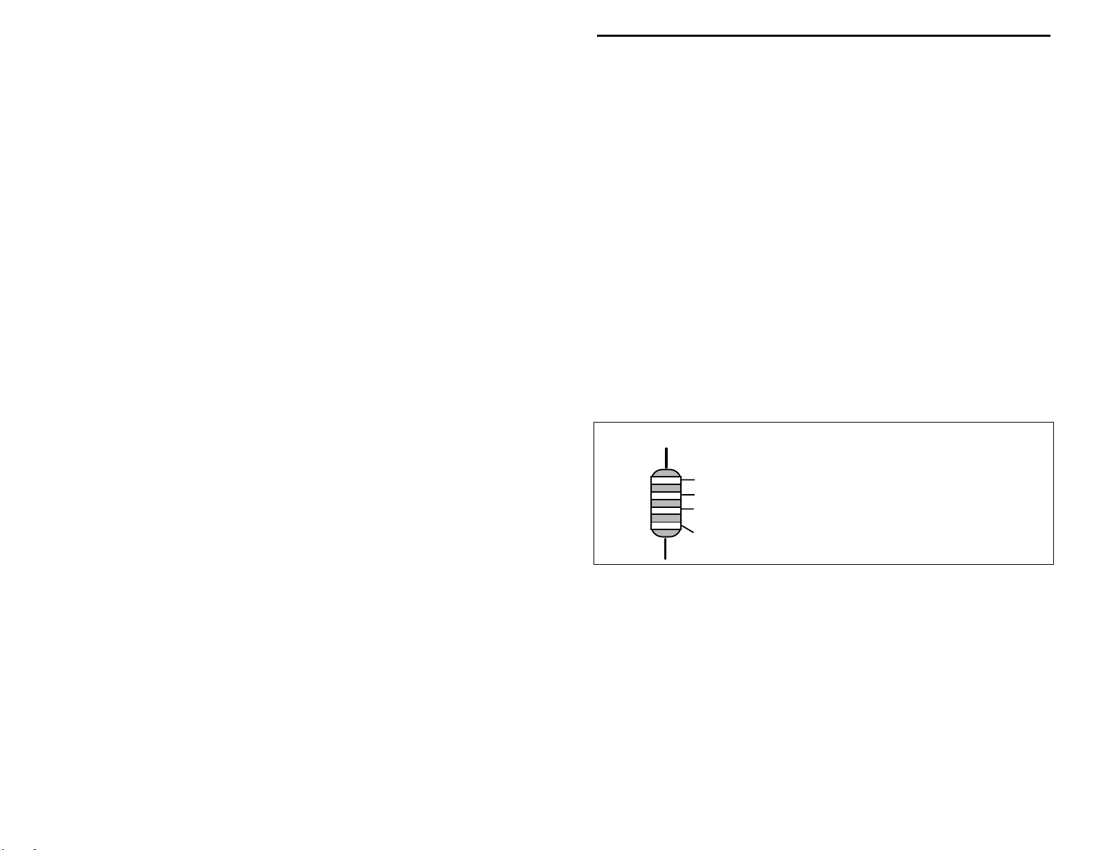
This VEC kit contains molded chokes which appear, at first glance, similar to
resistors in both shape and band marking. However, a closer look will enable
3
Page 6
VEC-101K Owner's Manual Shortwave Converter Kit
you to differentiate between the two—chokes are generally larger in diameter
and fatter at the ends than resistors. When doing your inventory, separate out
any chokes and consult the parts list for specific color-code information.
Reading Capacitors:
Unlike resistors, capacitors no longer use a color code for
value identification. Instead, the value, or a 3-number code, is printed on the
body.
Value Code
10 pF = 100
100 pF = 101
1000 pF = 102
.001 uF = 102*
.01 uF = 103
.1 uF = 104
Multilayer
(270 pF)
271
Ceramic Discs
(.001 uF) (.1 uF)
102
104
Electrolytic
1 uF
1uF
|
35V
|
+
-
As with resistors, it’s helpful to sort capacitors by type, and then to arrange them
in ascending order of value. Small-value capacitors are characterized in pF (or
pico-Farads), while larger values are labeled in uF (or micro-Farads). The
transition from pF to uF occurs at 1000 pF (or .001 uF)*. Today, while most
monolithic (multilayer) and disc-ceramic capacitors are marked with a threenumber code, you may still find a .1 uF capacitor marked either “104” or “.1”.
For three digit codes, the first two digits indicate a numerical value, while the
last digit indicates a multiplier (same as resistors). The value is in pF; thus a
capacitor marked “104” is 100,000 pF, or .1 uF.
Electrolytic capacitors are always marked in uF. Electrolytics are polarized
devices and must be oriented correctly during installation. If you become
confused by markings on the case, remember the uncut negative lead is slightly
shorter than the positive lead.
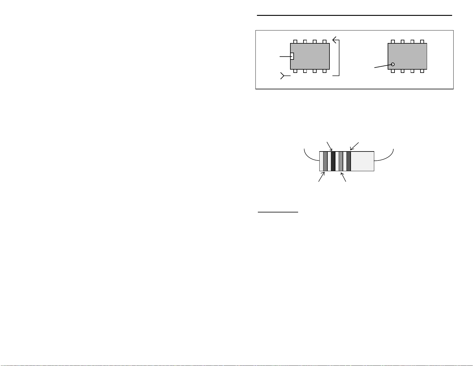
Integrated Circuits:
Proper IC positioning is indicated by a dot or square
marking located on one end of the device. A corresponding mark is silkscreened on the PC board and printed on the kit’s parts-placement diagram. To
identify specific IC pin numbers for testing purposes, see the following diagram.
Pin numbers always start at the keyed end of the case and progress
counterclockwise around the device, as shown:
4
Page 7
VEC-101K Owner's Manual Shortwave Converter Kit
8 7 6 5
Installation
Key
1 2 3 4
Pin Numbers
Installation
Key
This VEC kit contains molded chokes which appear, at first glance, similar to
resistors in bo th shape and band marking. When doing your inventory, separat e
out any chokes and consult the parts list for specific color-code information.
2 nd
1 st
tolorance
3 rd
Important Note:
interested in the value, and the parts lists and assembly directions will only
specify the colors of the first three color bands.
The fourth color band indicates the tolerance. We are
5
Page 8

VEC-101K Owner's Manual Shortwave Converter Kit
PARTS LIST
Your kit should contain all of the parts listed. Please identify and inventory each
item on the checklist before you start building. If any parts are missing or
damaged, refer to the manual’s warranty section for replacement instructions. If
you can’t positively identify an unfamiliar item on the basis of the information
given, set it aside until all other items are checked off. You may then be able to
identify it by process of elimination. Finally, your kit will go together more
smoothly if parts are organized by type and arranged by value ahead of time.
Use this inventory as an opportunity to sort and arrange parts so you can identify
and find them quickly.
CAPACITORS:
Qty Part Description Designation
"
!
2 12 pF monolithic (12 or 120) C1,C2
!
1 47 pF disc ceramic (47 or 470) C3
!
2 47 pF monolithic (47 or 470) C9,C9
!
2 .1 uF monolithic (.1 or 104) C6,C7
!
2 .1 uF disc ceramic (104) C4,C5
!
4 100 pF ceramic trimmer C10,C11,C12,C13
SEMICONDUCTORS:
Qty Part Description Designation
"
!
1 NE602, SA602 or NE612 linear IC U1
INDUCTORS:
Qty Part Description Designation
"
!
1 180 uH molded inductor (brown-gray-brown) L5
!
2 33 uH molded inductor (orange-orange-black) L2,L4
!
2 10 uH molded inductor (brown-black-black) L2,L4
!
2 3.9 uH molded inductor (orange-white-gold) L1,L3
!
2 1.2 uH molded inductor* (brown-red-gold) L1,L3
* Your kit may include a different looking 1.2 uH inductor. The full color band
is silver-brown-gold-red-silver.
6
Page 9
Page 10

VEC-101K Owner's Manual Shortwave Converter Kit
STEP-BY-STEP ASSEMBLY INSTRUCTIONS
Before assembling your kit, please take time to read and understand the VEC kit
warranty printed on t he inside co ver of this manual. Read thro ugh the assembly
instructions to make sure the kit does not exceed your skill level. Once
construction is started, the kit is non-returnable. Finally, if you haven’t already
done so, please verify that all parts listed in the inventory are included. If
anything is missing or broken, refer to the warranty instructions for replacing
missing or damaged parts.
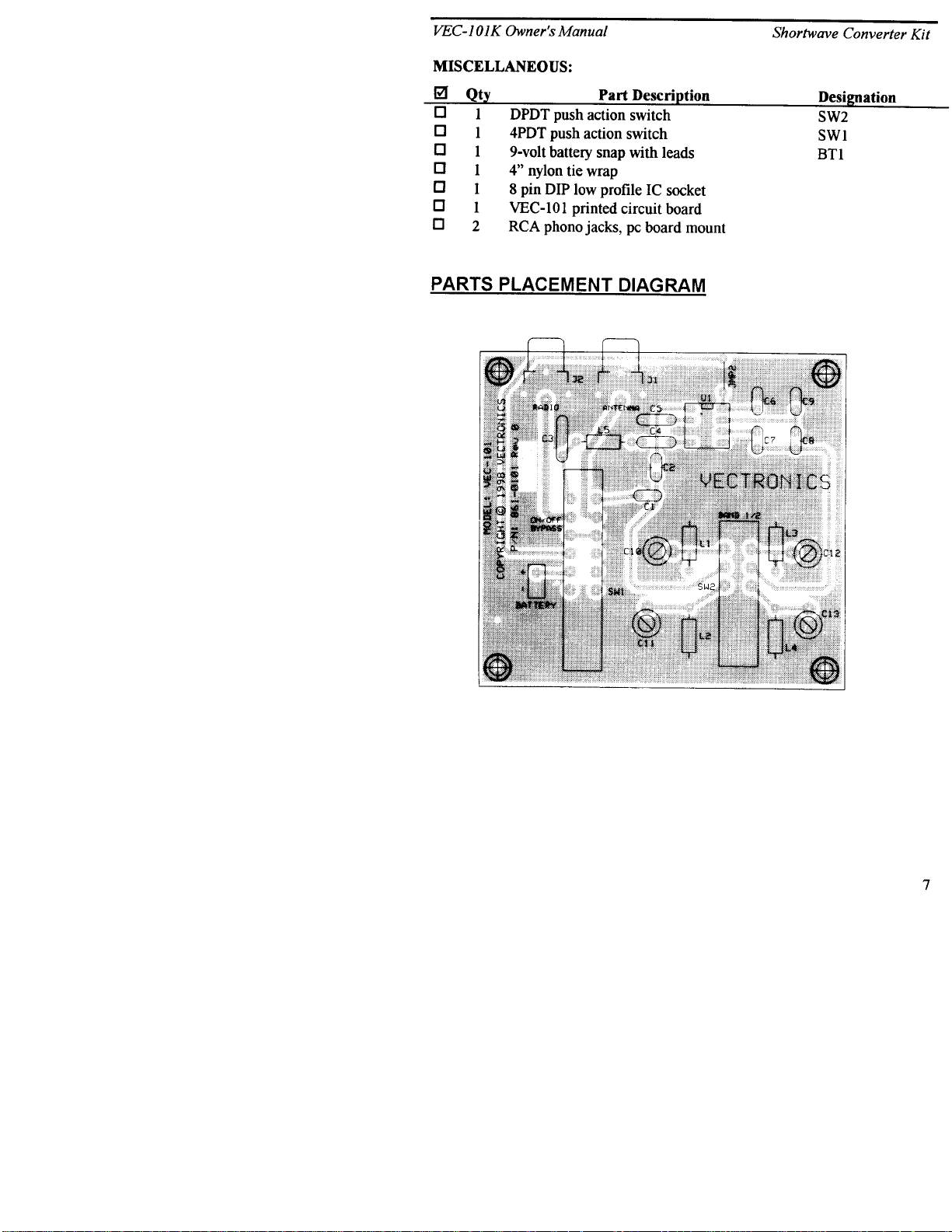
First, a few notes and comments to help you along. Part designators for
components such as L1, C3, etc., appear on the silk-screened legend on the
component-mounting side of the printed circuit board. These correspond to the
drawing shown in the “Part Placement Diagram” section of this manual. The
parts are inserted on the silk-screen side of the board. All capacitors should be
installed with their bodies as close to the PC board as possible; this is very
important in RF circuits.
If you have last-minute questions concerning what tools or materials are needed
to assembly this kit, please refer back to the section entitled “Before You
Begin”.
“Install”
When you are directed to install a part, this means to locate, identify,
and insert the part into its mounting holes on the PC board. T his includes prebending or straightening leads as needed so force is not required to seat the part.
Once a component is mounted, bend each lead over to hold it in place. Make
sure trimmed leads don’t touch other pads and tracks, or a short circuit may
result:
2SC2498
(C2498)
“Solder”
When you are directed to solder, this means to solder the part’s leads
in place, and to inspect both (or all) solder connections for flaws or solder
bridges. If no soldering problems are noted, nip off the excess protruding leads
with a sharp pair of side cutters.
We'll begin with the molded chokes
8
Page 11

VEC-101K Owner's Manual Shortwave Converter Kit
Phase 1: Molded Chokes
Important Note:
directions. The fourth band is for tolerance and may be disregarded.
only the first three color bands are specified in the following
Locate the 180-uH molded choke (brown-gray-brown).
! !
1. Install and solder the 180-uH choke (brown-gray-brown) at location
L5 on the PC board.
Important Note:
cover. Chokes L1 and L3 are used for the lowest frequency band, chokes L2
and L4 are selected for the higher frequency band. Band selection is via switch
SW2. Push button is in for lowest frequency band, push button is out for
highest frequency band.
You need to determine the two SW bands the VEC101 will
The choke values for the following steps are determined by the following:
Desired
coverage
L1, L3
low range
L2, L4
high range
3.0 to 5.8 MHz 33 uH, 33 uH use low range
5.0 to 9.0 MHz 10 uH, 10 uH 10 uH, 10 uH
8.0 to 14.5 MHz 3.9 uH, 3.9 uH 3.9 uH, 3.9 uH
13.9 to 23 MHz use high range 1.2 uH, 1.2 uH
Table 1
Example:
Your favorite SW bands are 31 Meters and 49 Meters. 49 Meters is from 5.95
MHz to 6.20 MHz. 31 Meters spans from 9.50 MHz to 9.90 MHz.
According to the data in Table 1, 10-uH chokes should be used for the 49-Meter
band (5.95 to 6.20 MHz). Because this is the lowest frequency band of the two
we are selecting, the 10-uH chokes will be used at locations L1 and L3.
Referring to Table 1 again shows for 30 Meters (9.5 to 9.9 MHz) coverage 3.9uH chokes should be used at locations L2 and L4.
! !
2. Determine the two shortwave frequency ranges o r SW b ands you wish
to monitor. Refer to Table 1 for the proper choke values. Note: Some
bands, such as 16 and 13 Meters, share the same choke value. Only
one of those two bands may be covered.
9
Page 12

VEC-101K Owner's Manual Shortwave Converter Kit
! !
3. Select the two chokes to be used for the lowest frequency Short Wave
band. Install and solder at the following locations (both chokes must
be identical values):
! !
4. L2, selected choke value
! !
5. L4, selected choke value
! !
6. Select the two chokes to be used for the highest frequency Short Wave
band. Install and solder at the following locations (both chokes must
be identical values):
! !
7. L1, selected choke value
! !
8. L3 selected choke value
Phase 2: Capacitors
Locate the four 100-pF ceramic trimmer capacitors. Install and solder at the
following locations:
! !
1. C10 100-pF ceramic trimmer
! !
2. C11 100-pF ceramic trimmer
! !
3. C12 100-pF ceramic trimmer
! !
4. C13 100-pF ceramic trimmer
Locate the two .1-uF ceramic disc capacitors (.1 or 104). Do not confuse the two
.1 ceramic disc capacitors with the two .1 monolithic capacitors! Install and
solder at the following locations:
! !
5. C4 .1-uF ceramic disk (.1 or 104)
! !
6. C5 .1-uF ceramic disk (.1 or 104)
Important Note:
the spacing isn't right, pre-form the leads to the correct spacing before
installation!
Mast Clamp
never use force to seat a monolithic cap into the PC board. If
Small Diameter
Aluminum Tubing or Rod
7-8 Turns RG-58
1-1/2" PVC Pipe
(Thick Wall)
30"
TV Mast
106"
Locate the two .1-uF monolithic capacitors (.1 or 104). Install and solder at the
following locations:
! !
7. C6 .1-uF monolithic (.1 or 104)
10
Page 13
VEC-101K Owner's Manual Shortwave Converter Kit
! !
8. C7 .1-uF monolithic (.1 or 104)
Locate the two 47-pF monolithic capacitors (47 or 470). Do not use the 47-pF
disc ceramic at this point! Install and solder at the following locations:
! !
9. C8 47-pF monolithic (47 or 470)
! !
10. C9 47-pF monolithic (47 or 470)
! !
11. Locate the 47-pF (47 or 470) ceramic disc capacitor. Install and
solder at location C3.
Locate the two 12-pF monolithic capacitors (12 or 120). Install and solder at the
following locations:
! !
12. C1 12-pF monolithic (12 or 120)
! !
13. C2 12-pF monolithic (12 or 120)
Phase 3: Jumpers/IC Sockets and Chips
Select a scrap capacitor lead end for use as a jumper wire, as shown below. Use
needle-nose pliers to form to fit, making sure the jumper lies flat on the PC
board when installed:
span
! !
1. Prepare, install, and solder a jumper wire at JMP2.
Locate the 8-pin DIP integrated IC socket. Note that the socket is “keyed”, and
should be installed with its key aligned to the silk-screened outline on the PC
board.
8 7 6 5
Installation
Key
1 2 3 4
Pin Numbers
! !
2. Install and solder the 8-pin IC socket at location U1. Observe proper
orientation!
discarded lead end
Top view of socket
11
Page 14

VEC-101K Owner's Manual Shortwave Converter Kit
a
The IC body has a small notch, or key, molded at one end, indicating pins 1 and
8. A small dimple-like body-molding is often found adjacent to pin 1. Some IC
packages may include both key indicators.
discarded le
span
Locate the 8-pin NE602 (may be marked as NE602, SA602, or NE612).
! !
3. Align the body of the NE602 to correspond with the key of socket U1.
Loosely insert the NE602 pins into socket U1. All 8 pins should fit
freely into the socket openings. If not, straighten the IC pins until they
do. Using firm and steady pressure, fully seat the IC into the socket.
! !
4. Locate the push-action DPDT band switch. Install and solder at SW2.
The push shaft should extend over the front of the board. Be sure the
switch is fully seated and level before soldering.
! !
5. Locate the push-action 4PDT power/bypass switch. Install and solder
at location SW1. The push shaft should extend over the front of the
board. Be sure the switch is fully seated and level before soldering.
SW1
SW2
Push-rod
Phase 4: Phone Jacks/Battery Clip/Tie Wrap
12
Page 15

VEC-101K Owner's Manual Shortwave Converter Kit
Locate the two RCA phono jacks. Install and solder at the following locations
(be sure the leads are fully seated before soldering):
! !
1. J1 -- install and solder a RCA phono jack.
! !
2. J2 -- install and solder a RCA phono jack.
Locate the 9-volt battery snap.
! !
3. Solder the RED positive lead to the positive (+) termination shown on
the silk-screened legend.
! !
4. Solder the BLACK negative lead to the negative (-) termination shown
on the silk-screened legend.
Tie-wrap
+
red
Stress Relief
SW1
Push-rod
black
! !
5. Locate the nylon wire tie wrap. Loop the nylon tie through the stress
relief hole (see above) and around the battery lead wires.
! !
6. Run the nylon ta il through the locking head of the tie, and pull until
snug. Trim excess nylon tai l.
This concludes the construction phase of your receiver. You deserve a break!
When you come back, be ready to give your work a thorough "QC" quality
control check before moving on to the testing and alignment section.
! !
Please go over the board and verify that all parts are properly installed.
Check all solder connections, and redo those that look suspect.
TESTING AND ALIGNMENT
Understanding alignment: This converter is intended to be used with a tunable
communications receiver that covers from 540 to 1600 (or 1710) kHz. For
13
Page 16

VEC-101K Owner's Manual Shortwave Converter Kit
alignment, a communications receiver or car radio will be needed. The receiver
must be shielded, and one that requires an external antenna for reception.
Alignment consists of adjusting capacitors C10 and C12 for the highest
frequency band, and capacitors C11 and C13 for the lowest frequency band.
Capacitors C10 and C11 are part of the input tuning, and are set for best
sensitivity. Capacitors C12 and C13 set the Local Oscillator frequency for the
shortwave converter mixer.
Because we are using a tunable IF (a receiver covering 540 to 1600 kHz), the
Local Oscillator should be set for Low Side injection. Using high side injectio n
would result in the bands being tuned “backwards” across the dial. Let’s look at
an example and see what needs to be done.
Let’s assume we want the converter to cover the 41-Meter and 25-Meter
Shortwave broadcast bands. 41 Meters spans 7.100 to 7.300 MHz. We’ll begin
with the 41-Meter band alignment. Since this is the lowest frequency band, we
will be adjusting capacitors C11 and C13. (L2 and L4 both should be 10-uH
molded chokes.)
The tunable receiver starts at 540 kHz. If we have the 41-Meter band start at this
point, a dial reading of 540 kHz would equate to a receive frequency of 7.100
MHz. This is confusing, as there is no relationship between the two frequencies.
Instead, let’s set the Local Oscillator so dial reading of 1100 kHz (1.100 MHz)
corresponds to the beginning of the 41 Meter band at 7.100 MHz. A dial read of
1300 kHz would correspond to 7300 kHz (7.300 MHz), the upper frequency of
the 41-Meter band. . The correlation between the radio dial and the actual
receive frequency is easily understood. Except for 31 and 13 Meters, most of
the bands can be set to align with the AM broadcast band dial scale readings.
31-Meters begins at 9.500 MHz. This could equate to an IF. at 500 kHz (below
the tuning range of the radio) or 1500 kHz. Using 1500 kHz would require that
the radio tune to 1900 kHz, again out of range. Using 500 kHz would lose
coverage of the lower 40 kHz of the 31-Meter band, not too bad of a
compromise if dial correlation is important.
Worldwide Shortwave AM broadcast bands
Band Frequencies Tuning range LO setting
75 Meters 3.900 to 4.000 MHz 900kHz to 1000kHz 3.000 MHz
49 Meters 5.950 to 6.200 MHz 950kHz to 1200kHz 5.000 MHz
14
Page 17

VEC-101K Owner's Manual Shortwave Converter Kit
41 Meters 7.100 to 7.300 MHz 1000kHz to 1300kHz 6.000 MHz
31 Meters 9.500 to 9.900 MHz no recommendations
25 Meters 11.650 to 12.050 MHz 650kHz to 1250kHz 11.00 MHz
19 Meters 15.100 to 15.600 MHz 1100kHz to 1600kHz 14.00 MHz
16 Meters 17.550 to 17.900 MHz 550kHz to 900kHz 17.00 MHz
13 Meters 21.450 to 21.850 MHz no recommendations
The table shows the optimum LO settings for our example converter operating
on 41 and 25 Meters would be 6.00 MHz and 11.00 MHz, respectively.
Calculating the Local Oscillator Frequency:
When used with a receiver that covers from 540 to 1600 kHz, the converter can
cover any two 1060 kHz wide segments between 3 and 22 MHz. The Local
Oscillator frequency is the
corresponding AM broadcast band frequency.
Examples of good and poor correlation between the receiver and shortwave
frequencies :
Desired coverage Actual Coverage Receiver Tuning Local Oscillator
8.54 to 9.54 MHz
good correlation
8.00 to 9.00 MHz
poor correlation
difference
8540 to 9600 kHz 540 to 1600 kHz
8000 to 9060 kHz 540 to 1600 kHz
between the shortwave frequency and its
8000 kHz
(8.00 MHz)
7460 kHz
(7.46 MHz)
Performing Local Oscillator Alignment:
Using a shortwave receiver: If you own a good shortwave receiver that covers
to at least 22 MHz, it may be used for the Local Oscillator alignment.
1. Set up the shortwave receiver on your workbench. It should be equipped
with a short wire antenna that is run near the VEC-101K circuit board.
2. The low-frequency band Local Oscillator is aligned first.
3. Set the receiver to monitor the frequency the Local Oscillator is going to be
set to. If the receiver has a BFO, turn it on.
4. The push-button for the SW2 bandswitch should be in the “depressed” or
“in” position, selecting the low-frequency shortwave band.
5. Attach a fresh 9-volt battery to the VEC-101K battery clip.
6. Set SW1 power switch button to on, the “in” position.
15
Page 18

VEC-101K Owner's Manual Shortwave Converter Kit
7. Using a blade type alignment tool or small jeweler’s screwdriver, carefully
adjust ceramic trimmer capacitor C13 until the oscillator signal is heard
sweeping through the shortwave receiver.
8. Slowly adjust the trimmer C13 so the Local Oscillator signal falls exactly on
frequency (if the BFO is on, adjust for “zero beat”).
9. Set the receiver to the highest Local Oscillator frequency to be set.
10. Activate bandswitch SW2 so the shaft returns to the fully extended position
(high frequency band).
11. Adjust ceramic trimmer capacitor C12 until the Local Oscillator signal is
head sweeping across the receiver.
12. Carefully peak C12 so the Local Oscillator frequency falls exactly on the
receiver frequency (if the BFO is on, adjust for “zero beat”).
13. This completes the Local Oscillator alignment.
Using a frequency counter: A sensitive frequency counter is needed. Make up a
small “gimmick capacitor” using two or three inches of insulated wire twisted
together. The gimmick capacitor is used to couple the Local Oscillator signal
from pin 7 of the NE602 to the counter input. RF cables must be very short to
prevent signal attenuation. If more signal amplitude is needed, use an in line
broadband RF preamplifier. Many Tektronix scopes (465) have a vertical
amplifier output which may be used to drive a counter. Use the scope vertical
amplifier to amplify the level. Note that the gimmick capacitor will load the
oscillator, and pull its frequency to some extent.
Using off-air signals: Shortwave broadcasters operate on known schedules, and
often announce their frequencies throughout the broadcast or on the hour.
Popular Communications Magazine includes a monthly guide listing sho rtwave
broadcast times and frequency. Adjusting the Local Oscillator trimmers to find
areas of shortwave broadcast activity will get your converter into the “ballpark”.
Use the frequency announcements to fine tune the calibration.
Using a signal generator:
1. Set the signal generator to the lowest shortwave frequency (i.e.: 3900kHz
for 75 Meters).
The generator output should be set to about 20 uV, modulation should be AM
(1000-Hz tone) at 30% modulation.
16
Page 19

VEC-101K Owner's Manual Shortwave Converter Kit
2. Connect the signal generator output to RCA jack J1 on the VEC-201. Use
coaxial cable with suitable connectors or adapters.
3. .Connect the receiver antenna connector to RCA jack J2 on the VEC201.
Use coaxial cable with suitable connectors or adapters.
4. Set the converter bandswitch to the “in” position (low frequency band).
5. Set the receiver to the frequency corresponding to the lowest portion of the
Shortwave band being calibrated (i.e.: 900kHz for 3900kHz on the 75Meter band).
6. Attach a battery and turn on the converter.
7. Carefully adjust capacitor C13 until the signal generator signal is heard on
the receiver.
8. Increase the signa l generato r freque ncy slightly (20 or 30 kHz) and note i n
which direction the receiver has to be retuned to find it. If the receiver has
to be set lower in frequency to find the signal generator, the Local Oscillator
has been set for high-side injection. Continue with the alignment until the
proper low-side injection Local Oscillator setting is found.
9. Repeat the above steps to adjust the Local Oscillator on the higher
frequency band. Remember to set the bandswitch to the extended position.
Capacitor C12 is used to set the high-frequency band Local Oscillator
frequency. Set the receiver dial to correspond to the new band’s lower edge.
Set the signal generator to the new frequency.
Performing Antenna Trimmer Alignment:
The objective is to peak ceramic trimmer C10 for best signal reception on the
high- frequency band, and ceramic trimmer C11 for best signal reception on the
low-frequency band. The trimmers are peaked for best reception at the
approximate center of the band of interest. For example, for 41 Meters (7.10 to
7.30 MHz) the antenna trimmer would be tuned for maximum response at 7.165
MHz.
Using off-air signals: Once the Local Oscillators are set to frequency, antenna
trimmers C10 and C11 may be peaked for best reception. Tune into a weak
shortwave broadcaster, and peak the associated antenna trimmer for best volume.
On the lower shortwave bands, the trimmers can often be peaked for maximum
noise. It is possible to tune the trimmers to an image response, so be sure the
signal you’re peaking to is operating in the desired band!
Using a signal generator: Use the same basic setup suggested for the Local
Oscillator alignment with a signal generator. The signal generator is set to the
center of the desired shortwave band, and the receiver is tuned to the generator
17
Page 20

VEC-101K Owner's Manual Shortwave Converter Kit
signal. Decrease the signal generator output level until the signal is barely
audible. Adjust the appropriate antenna trimmer capacitor (C10 or C11,
depending on which band is being aligned) for the loudest signal. As the
trimmer is bro ught into t une, you may have to co ntinuously lower the gene rator
output to notice further improvements. Repeat for the second shortwave band.
OPERATING INSTRUCTIONS
Power requirements: The VEC-101K requires a 9-volt transistor battery for
operation. Alkaline batteries are recommended—they cost more initially, but are
more economical to use over the long run.
Enclosure: The VEC-101K should be mounted in an enclosure to protect it from
damage. Vectronics can supply enclosures for most of the Vectronics kit line.
The Vectronics enclosures have all needed buttons and knobs, and have decaled
front panels. If you chose to supply your own enclosure, it should be roomy
enough to house the battery.
Operating the unit: When power switch SW1 is set to “off” (push-button
extended) the 9-volt power is removed from the converter, and the antenna is
automatically connected directly to the receiver. Activating the power switch
places the converter in line between the antenna and receiver. Bandswitch SW2
is used to select the desired shortwave band. Depressing SW2 (button in) selects
the lower frequency shortwave band, releasing SW2 (button out) selects the
higher frequency shortwave band.
The car radio tuning control is used for tuning across the shortwave bands, just
as it would be used to tune across the AM broadcast band. The radio volume
and tone control are set for the best listening level. Turn the converter off when
not in use to conserve battery power.
Understanding Shortwave Broadcasting:
shortwave converter requires a basic knowledge of radio propagation, and where
SW broadcasts take place.
Where to listen:
Worldwide Shortwave AM Broadcast Bands
75 Meters 3.900 to 4.000 MHz
49 Meters 5.950 to 6.200 MHz
41 Meters 7.100 to 7.300 MHz
18
Getting the most from your
Page 21

VEC-101K Owner's Manual Shortwave Converter Kit
31 Meters 9.500 to 9.900 MHz
25 Meters 11.650 to 12.050 MHz
19 Meters 15.100 to 15.600 MHz
16 Meters 17.550 to 17.900 MHz
13 Meters 21.450 to 21.850 MHz
Time standards 2.5, 5.0, 7.335, 10.0, 15, 20 MHz
When to listen:
75 Meters:
especially in winter months. Shared with Amateur Radio.
49 Meters and 41 Meters:
These are very active and popular bands.
31 Meters and 25 Meters:
19 Meters:
and periods of high sunspot activity.
16 Meters:
sunspot activity.
13 Meters and 15 Meters:
peak of 11 year sunspot cycle. Excellent evening and nighttime propagation
possible during sunspot maximum.
Shortwave broadcasters are very dynamic. Frequencies are often changed
several times a day, even hourly, and different bands are more favored as the
changing seasons affect propagation. An even bigger influence is the 11 year
sunspot cycle. During the years of maximum sunspots activity flourishes across
the spectrum. During the years of low activity the 13 and 11 Meter bands may
appear to be totally inactive, and broadcasters crowd the 31, 41 and 49 Meter
bands. We are entering a new sunspot cycle, for the next several years
shortwave broadcasting will grow and new adventures will await you each day.
If your main interest is in shortwave English broadcasts aimed the United States,
remember that broadcasters chose time and frequencies that will reach the largest
targeted audience. Very few shortwave stations are interested in reaching New
York City at 3:00AM when most folks are in bed.
very local daytime coverage; very good evening and nighttime band,
Late afternoon, early evenings and nighttime band.
Good daytime and nighttime reception.
Excellent daytime listening. Good nighttime during summer months
Excellent daytime listening. Activity best during periods of high
Excellent daytime listening. Activity best during
Popular Communications Magazine publishes a monthly list of active shortwave
stations, noting the language, frequency and times of bro adcast.
19
Page 22

VEC-101K Owner's Manual Shortwave Converter Kit
Connecting to your car’s AM receiver:
Receiver requirements:
The output of the converter is designed for receivers
covering the standard AM broadcast band—540 kHz to 1600 kHz. Since the
receiver is being used a “tunable IF.” (the shortwave stations are tuned across
the receiver’s dial) it must meet certain requirements. The receiver must be well
shielded, and require an external antenna to hear signals on the broadcast
band. This is because we don’t want AM band broadcast signals competing with
the shortwave signals. The ideal receiver is a car radio. They are well-shielded
(to keep out ignition noise) and will only receive signals when an external
antenna is attached.
Connecting the converter to the car receiver and antenna:
Auto receivers use
very short antennas that are very reactive (offer a poor match) at the broadcast
band frequencies. The antenna cable is a special very-high impedance coax.
Using standard 50 or 75-ohm cables would severely attenuate the received
signals. Connecting cables between the VEC-101K and auto receiver can made
from sections of automotive antenna extension cables. Radio Shack carries
these in different lengths. Most automotive radios use Motorola
TM
style antenna
jacks and plugs. (Some newer vehicles use a new miniaturized style.) You will
need to make up interconnecting cables to mate with the RCA fittings on the
VEC-101K. The cables must be long enough to permit the antenna lead to reach
the converter’s location, and for the converter output to reach the receiver
antenna input connector.
Female Motorola
Male RCA
To car antenna
To J1
Cable A
Male Motorola
to car radio To J2
Cable B
Male RCA
Cable A:
Cable A is used to extend the existing automotive antenna lead to
reach the converter enclosure. One end is a Motorola female connector to mate
with the male connector on the antenna cable. The other end of the cable is
terminated with a solder-on RCA male connector to mate with jack J1 (antenna)
on the VEC-101K. The cable can be made by cutting the male connector off of
20
Page 23

VEC-101K Owner's Manual Shortwave Converter Kit
an extension cable from Radio Shack, and soldering a RCA phono connector in
its place.
Cable B:
antenna jack. On one end is a Motorola male connector to mate with the
automotive receiver antenna jack. The other end is terminated with a solder-on
RCA male connector to mate with jack J2 (radio) on the VEC-101K. The cable
can be made by cutting the female connector off of an extension cable from
Radio Shack, and replacing it with a solder-on RCA phono connector.
Using other antennas:
The convert er is d esi gned to work with shor t a ntenna s, using a l ong wire ante nna
may overload the converter. Try using an active antenna if more sensitivity is
needed.
Use with home receivers:
Many higher quality AM or AM/FM receivers have provisions for connecting an
external AM antenna. The output of the VEC-101K converter may be feed to a
receiver that has provisions for an external AM antenna. This includes many HIFI tuners that include AM broadcast band coverage. A short wire antenna will
be needed for the converter. 10 or 20 feet of wire will do in most woodenframed structures. If the building construction overly attenuates shortwave
signals, you may need to run a short outdoor antenna. Small active antennas are
ideal for this purpose.
Cable B is used to connect the converter to the automotive receiver
IN CASE OF DIFFICULTY
Only high-quality components and proven circuit designs are used in Vectronics
kits. In very rare instances is a defective component the source of a problem.
Replacement of defective parts is covered in the
percent of the kits returned for factory repair are due to soldering problems or
parts in the wrong locations. We advise repeating the assembly instructions
step-by-step, looking for mistakes or soldering problems. Be especially wary of
electrolytic capacitors and semiconductors. Kit builders often miss obvious
mistakes. What is needed is a “fresh” set of eyes. Enlist a friend to go over
your work.
Always check the obvious! Has the battery worn down? Is the power switch on?
Check all cables and connectors.
Receiver overloads:
extremely strong--str ong enough to overload the converte r. Try using a smalle r
Under certain conditions shortwave signals may be
Warranty
section. Nine ty-five
21
Page 24

VEC-101K Owner's Manual Shortwave Converter Kit
antenna. If the signals are coming from out-of-band stations using a preselector
in line with the antenna will help to reduce the level of the interfering signal.
Image problems:
shortwave bands. The best solution is using a preselector in line with the antenna
to reduce the level of the interfering signal.
Signals drift out of tune:
converter should be located away from heater or air-conditioning ducts! Rapid
temperature changes will cause drifting.
AM Broadcast stations are heard across the dial:
and input tuning give good rejection of AM broadcast signals; but, it is possible
for very strong signals to leak around the converter. This is the nature of the
design. A preselector may help reduce the problem to an acceptable level. If the
offending station prevents reception of a favorite shortwave station, adjust the
local oscillator trimmer so the shortwave station falls on a quiet channel.
If all else fails, refer to the
This problem will be more pronounced on the higher
This could be caused by a failing battery. Also, the
The balance mixer design
Warranty
for factory repair options.
THEORY OF OPERATION AND SPECIFICATIONS
Technical Circuit Description:
Input selectivity is provided by LC combinations L1/C10 and L2/C11. A single
tuned stage is used to achieve the needed 1.06 MHz tunable IF bandwidth.
Coupling capacitors C1 and C2 are used for the impedance transformation
needed between the antenna and tuned band-pass circuit, and to the 2000-ohm
input impedance of the NE602 mixer. The NE602 is an active doubly-balance
Gilbert ce ll mixer. The d oubly-balanc ed mixer enhance s attentuatio n of IF band
signals.
A broadband L-type matching circuit (L5, C3) is used between the 2000-ohm
mixer output and the receiver IF. output jack J2.
The NE602 also contains the local oscillator. All fixed capacitors in the
oscillator section are monolithic types for good stability. LC combinations
L3/C12 and L3/C13 form the oscillator tank circuits.
Specifications:
I.F. Range:.................................530 to 1710 kHz (limited by receiver)
Coverage: .................................. two 1 MHz wide bands between 3 and 22 MHz
Bypassing:................................. unit bypassed when power is off
Antenna:.................................... 60 mW into 8-ohm load
Impedance:................................ matched for hi Z automotive antenna systems
22
Page 25

Page 26

VEC-101K Owner's Manual Shortwave Converter Kit
ENCLOSURE
Vectronics has designed a matching enclosure just for your VEC-101K
Shortwave Converter Kit. The matching enclosure is an all metal box which
includes push-button caps, hardware, decals, and rubber feet.
Model: VEC-101KC.
To install your converter in the VEC-101KC matching enclosure follow these
instructions (read all instructions before beginning ... take your time):
1.
Find the front panel decal and rear panel decal; separate using scissors. Be sure to
leave excess decal material around the edges. Put the rear panel decal on first. This
is done by:
using a piece of cloth and alcohol.
adhesive.
Gently rub the alignment circles with your finger--if the circles are centered in the
enclosure holes (also check the corner alignment marks) secure the decal by rubbing
and removing all air bubbles.
decal accordingly then secure.
away the unused edges (cut from the adhesive side) and cut out the component holes
(cut from the description side).
2.
Next, install the two L-brackets on the chassis using two of the 3/16" screws. The
longer side of the L-bracket must be connected to the chassis using the two h oles
centered on each edge o f the enclosure. Refer to the diagram on th e next page for
location and orientation.
3.
Install the four 1/2" mounting screws next. Insert the screws, from the bottom,
through the four holes relatively close to each corner of the chassis.
4.
Place the four 3/16" round spacers on the mounting screws.
5.
Now insert the PC board. This must be done by:
at an angle so the switches ent er their respective ho les.
the board. Make sure the mounting screws align with the mounting holes in the PC
board before pushing.
6.
Use the four hex nuts to secure the PC board. Be certain all appropriate components
are centered with the enclosure holes before tightening.
7.
Find the two switch caps. Align a switch cap with SW1 and push it on. If it is
difficult to push on, then rotate it 90° and try again. Repeat for SW2.
8.
Locate the piece of double-sided tape. This is to be used for holding the 9-volt
battery clip in place. Locate a place on the underside of the top cover where the
battery will not interfere with any components. Peel off the backing of the tape and
stick it to the chosen location.
8.
The top should be installed next. Use the two remaining 3/16" screws for securing
the top to the L-brackets. Make sure the L-brackets are aligned properly.
9.
Place the four rubber feet on the bottom of the enclosure at the corners.
c.)
Place the decal on the rear panel without securing it completely.
a.)
Remove all debris and oil from the chassis. This should be done
b.)
Remove the crack and peel to expose the
e.)
If the alignment circles are not centered, adjust the
f.)
Use a penknife, or small Exacto
g.)
Repeat this procedure for the front panel.
a.)
Insert the front of the PC board
b.)
Push down on the rear of
TM
knife, to cut
d.)
24
Page 27

 Loading...