

Page 1

VEC-1012K Owner’s Manual
INTRODUCTION
If you like prowling the airwaves to gather news first-hand, the VEC-1012K is
the perfect kit for you! Tune in local fire, police, ambulance, public service,
commercial business, and marine traffic as you search for real-life on-air drama.
Before you know it, you'll master 2-way radio lingo, special operating
procedures, and police 10-codes as you ferret out the "real story" behind the
news! You'll also master hands-on electronic construction skills. Detailed stepby-step assembly instructions guide you through each stage, and clearlypresented alignment procedures ensure top performance without need for
expensive test equipment. Your receiver is built around a Motorola IC designed
especially for na rrow-band FM communicatio n radios, so i t's guaranteed to pull
in weak signals--just like the best commercially-built scanners and two-way
transceivers. Electronic tuning lets you scan the band quickly for activity
without need for entering complex strings of microprocessor commands. And,
once you've found the action, your radio's fully adjustable "tail-free" squelch
eliminates annoying background noise between transmissions. The VEC-1012K
uses minimal energy, and can run for many hours from its self-conta ined 9-volt
flat-pack alkaline battery. Plug in a 8-ohm speaker or use headphones for loudand-clear reception. All circuitry is self-contained on a rugged 3" x 3.2" pc
board.
TOOLS AND SUPPLIES
Construction Area: Kit construction requires a clean, smooth, and well-lighted
area where you can easily organize and handle small parts without losing them.
An inexpensive sheet of white poster board makes an excellent construction
surface, while providing protection for the underlying table or desk. Welldiffused overhead lighting is a plus, and a supplemental high-intensity desk lamp
will prove especially helpful for close-up work. Safety is an important
consideration. Be sure to use a suitable high-temperature stand for your
soldering iron, and keep the work area free of combustible clutter.
Universal Kit-building Tools: Although your particular kit may require
additional items to complete, virtually all construction projects require a work
area outfitted with the following tools and supplies:
! Soldering Iron (grounded-tip and temperature-controlled preferred)
! High-temperature Iron Holder with Cleaning Sponge
! Rosin-core Solder (thin wire-size preferred)
! Needle Nose Pliers or Surgical Hemostats
! Diagonal Cutters or "Nippy Cutters"
1
Page 2

VEC-1012K Owner’s Manual
! Solder Sucker, Vacuum Pump, or Desoldering Braid
! Bright Desk Lamp
! Magnifying Glass
Special Tools for This Kit:
! 6-32 screw, at least 3/4" long, for winding coils.
! Insulated hex-head tuning wand.
! Small flat-blade screwdriver or tuning wand.
! Voltmeter, digital or analog.
! VHF "high-band" antenna to receive off-air signals.
BEFORE YOU START BUILDING
Experience shows there are four common mistakes builders commonly make.
Avoid these, and your kit will probably work on the first try! Here's what they
are:
1. Installing the Wrong Part: It always pays to double-check each step. A 1K
and a 10K resistor may look almost the same, but they may act very
differently in an electronic circuit! Same for capacitors--a device marked
102 (or .001 uF) may have very different operating characteristics from on
marked 103 (or .01uF).
2. Installing Parts Backwards: Always check the polarity of electrolytic
capacitors to make sure the positive (+) lead goes in the (+) hole on the
circuit board. Transistors have a flat side or emitter tab to help you identify
the correct mounting position. ICs have a notch or dot at one end indicating
the correct direction of insertion. Diodes have a banded end indicating
correct polarity. Always double-check--especially before applying power to
the circuit!
3. Faulty Solder Connections: Inspect for cold-solder joints and solder
bridges. Cold solder joints happen when you don't fully heat the connection-or when metallic corrosion and oxide contaminate a component lead or pad.
Solder bridges form when a trail of excess solder shorts pads or tracks
together (see solder tips below).
4. Omitting or Misreading a Part: This is easier to do than you might think!
Always double-check to make sure you completed each step in an assembly
sequence.
2
Page 3

VEC-1012K Owner’s Manual
Soldering Tips: Cleanliness and good heat distribution are the two secrets of
professional soldering. Before you install and solder each part, inspect leads or
pins for oxidation. If the metal surface is dull, sand with fine emery paper until
shiny. Also, clean the oxidation and excess solder from the soldering iron tip to
ensure maximum heat transfer. Allow the tip of your iron to contact both the
lead and pad for about one second (count "one-thousand-one") before feeding
solder to the connection. Surfaces must become hot enough for solder to flow
smoothly. Feed solder to the opposite side of the lead from your iron tip--solder
will wick around the lead toward the tip, wetting all exposed surfaces. Apply
solder sparingly, and do not touch solder directly to the hot iron tip to promote
rapid melting.
Desoldering Tips: If you make a mistake and need to remove a part, follow
these instructions carefully! First, grasp the component with a pair or hemostats
or needle-nose pliers. Heat the pad beneath the lead you intend to extract, and
pull gently. The lead should come out. Repeat for the other lead. Solder may
fill in behind the lead as you extract it--especially if you are working on a
double-sided b o ar d with plat e-thr o ugh hol es. Sho uld this ha pp e n, tr y heat ing the
pad again and inserting a common pin into the hole. Solder won't stick to the
pin's chromium plating. When the pad cools, remove the pin and insert the
correct component. For ICs or multi-pin parts, use desoldering braid to remove
excess solder before attempting to extract the part. Alternatively, a low-cost
vacuum-bulb or spring-loaded solder sucker may be used. Parts damaged or
severely overheated during extraction should be replaced rather than reinstalled.
Work Habits: Kit construction requires the ability to follow detailed
instructions and, in many cases, to perform new and unfamiliar tasks. To avoid
making needless mistakes, work for short periods when you're fresh and alert.
Recreational construction project are more informative and more fun when you
take your time. Enjoy!
Sorting and Reading Resistors: The electrical value of resistors is indicated by
a color code (shown in the following chart). You don't have to memorize this
code to work with resistors, but you do need to understand how it works:
Resistor Color Code
1st Digit
2nd Digit
Multiplier
Tolerence
(gold or silver)
Black = 0 (tens)
Brown = 1 (hundreds)
Red = 2 (K)
Orange = 3 (10K)
Yellow = 4 (100K)
Green = 5 (1Meg)
Blue = 6
Violet = 7
Gray = 8
White = 9
Silver = 10%
Gold = 5%
When you look at a resistor, check its multiplier code first. Any resistor with a
black multiplier band falls between 10 and 99 ohms in value. Brown designates
3
Page 4

VEC-1012K Owner’s Manual
a value between 100 and 999 ohms. Red indicates a value from 1000 to 9999
ohms, which is also expressed as 1.0K to 9.9K. An orange multiplier band
designates 10K to 99K, etc. To sort and inventory resistors, first separate them
into groups by multiplier band (make a pile of 10s, 100s, Ks, 10Ks, etc.). Next,
sort each group by specific value (1K, 2.2K, 4.7K, etc.). This procedure makes
the inventory easier, and also makes locating specific parts more convenient later
on during construction. Some builders find it especially helpful to arrange
resistors in ascending order along a strip of double-sided tape.
Some VEC kits may contain molded chokes which appear, at first glance, similar
to resistors in both shape and band marking. However, a closer look will enable
you to differentiate between the two--chokes are generally larger in diameter and
fatter at the ends than resistors. When doing your inventory, separate out any
chokes and consult the parts list for specific color-code information.
Reading Capacitors: Unlike resistors, capacitors no longer use a color code for
value identification. Instead, the value, or a 3-number code, is printed on the
body.
Value Code
10 pF = 100
100 pF = 101
1000 pF = 102
.001 uF = 102*
.01 uF = 103
.1 uF = 104
Multilayer
(270 pF)
271
Ceramic Discs
(.001 uF) (.1 uF)
102
104
Electrolytic
1 uF
1uF
|
35V
|
+
-
As with resistors, it's helpful to sort capacitors by type, and then to arrange them
in ascending order of value. Small-value capacitors are characterized in pF (or
pico-Farads), while larger values are labeled in uF (or micro-Farads). The
transition from pF to uF occurs at 1000 pF (or .001 uF)*. Today, most
monolithic and disc-ceramic capacitors are marked with a three-number code.
The first two digits indicate a numerical value, while the last digit indicates a
multiplier (same as resistors).
Electrolytic capacitors are always marked in uF. Electrolytics are polarized
devices and must be oriented correctly during installation. If you become
confused by markings on the case, remember the uncut negative lead is slightly
shorter than the positive lead.
Diodes: Diodes are also polarized devices that must be installed correctly.
Always look for the banded or cathode end when installing, and follow
instructions carefully.
4
Page 5
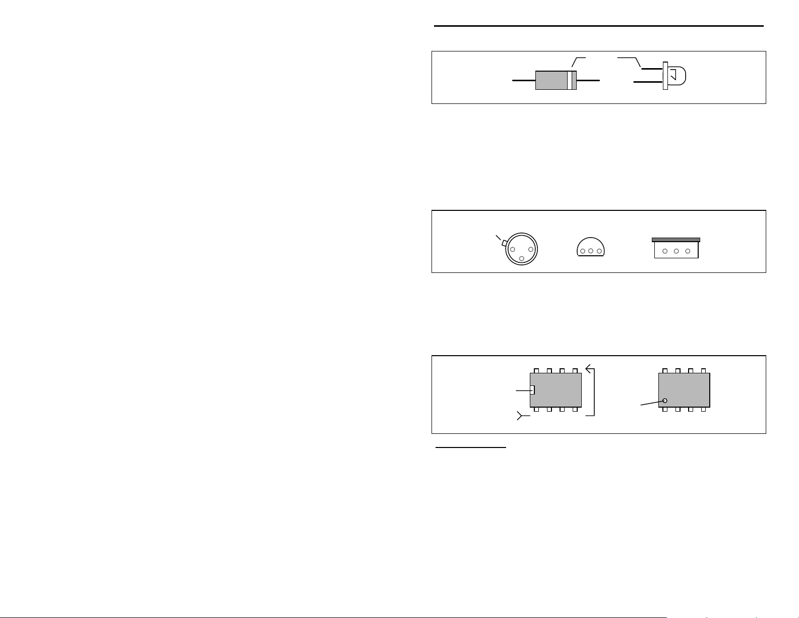
Cathode
VEC-1012K Owner’s Manual
(shorter Lead)
Diode
LED
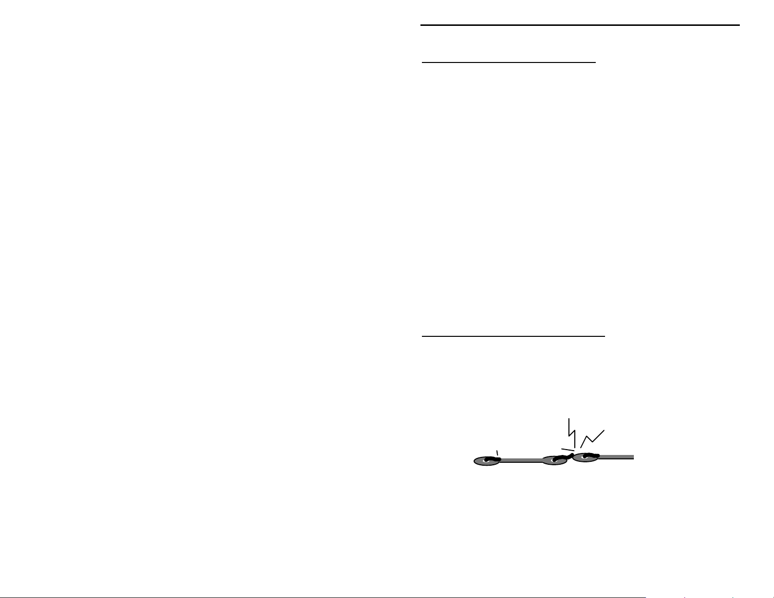
Transistors: If transistors are installed incorrectly, damage may result when
power is applied. Transistors in metal cases have a small tab near the emitter
lead to identify correct positioning. Semiconductors housed in small plastic
cases (TO-92) have an easily-identified flat side to identify mounting orientation.
Many specialized diodes and low-current voltage regulators also use this type
packaging. Larger plastic transistors and voltage regulators use a case backed
with a prominent metal tab to dissipate heat (T-220). Here orientation is
indicated by the positioning of the cooling tab.
Metal Can Device Plastic Device Tab-cooled Device
Emitter
Flat Side
Metal Tab
Integrated Circuits: Proper IC positioning is indicated by a dot or square
marking located on one end of the device. A corresponding mark will be silkscreened on the PC board and printed on the kit's parts-placement diagram. To
identify specific IC pin numbers for testing purposes, see the diagram below.
Pin numbers always start at the keyed end of the case and progress counterclockwise around the device, as shown:
8 7 6 5
Installation
Key
PARTS LIST
1 2 3 4
Pin Numbers
Installation
Key
Your kit should contain all of the parts listed below. Please identify and
inventory each item on the checklist before you start building. If any parts are
missing or damaged, refer to the manual's warranty section for replacement
instructions. If you can't positively identify an unfamiliar item on the basis of the
information given, set it aside until all other items are checked off. You may
then be able to identify it by process of elimination. Finally, your kit will go
together more smoothly if parts are organized by type and arranged by value
ahead of time. Use this inventory as an opportunity to sort and arrange parts so
you can identify and find them quickly.
5
Page 6

VEC-1012K Owner’s Manual
Resistors:
Qty Part Description Designation
"
!
1 22 ohm (red-red-black) R3
!
1 270 ohm (red-violet-brown) R4
!
1 470 ohm (yellow-violet-brown) R2
!
2 2.2K (red-red-red) R11,R14
!
2 4.7K (yellow-violet-red) R7,R17
!
2 10K (brown-black-orange) R5,R18
!
2 39K (orange-white-orange) R12,R15
!
1 47K (yellow-violet-orange) R8
!
4 100K (brown-black-yellow) R1,R9,R13,R19
!
2 10K potentiometer R6,R16
!
1 100K potentiometer R10
Capacitors:
Qty Part Description Designation
"
!
1 2.2 pF disc ceramic (2.2C) C3
!
8 .1 uF disc ceramic (104) C10,C11,C12,C21,C22,
C24,C26,C29
!
1 .05 uF disc ceramic (503) C27
!
1 6.8 pF disc ceramic (6.8J or 6.8C) C5
!
1 4.7 pF disc ceramic (4.7J or 4.7C) C1
!
5 .001 uF disc ceramic (102) C6,C13,C14,C25,C32
!
2 1 uF electrolytic C23,C28
!
2 10 uF electrolytic C30,C31
!
2 100 uF electrolytic C8,C9
!
2 15 pF multilayer (15 or 150) C17,C18
!
1 18 pF multilayer (18 or 180) C19
!
2 22 pF multilayer (27 or 270) C2,C4
Capacitors cont.
Qty Part Description Designation
"
!
1 56 pF multilayer (56 or 560) C20
!
1 100 pF multilayer (101) C7
!
2 470 pF multilayer (471) C15,C16
Semiconductors:
Qty Part Description Designation
"
!
1 5.1 volt zener diode, 1N751A D1
!
1 2SC2498 transistor Q1
!
1 MC13135 IC (24 pin) U1
6
Page 7

VEC-1012K Owner’s Manual
!
1 MC34119 IC (8 pin) U2
Inductors/Filters/Crystals
Qty Part Description Designation
"
!
1 24" length of #24 coil wire For L1,L2,L3
!
1 .074 uH slug-tuned, shielded (red) L4
!
1 660 uH adjustable, shielded (black) L5
!
1 10.245 crystal Y1
!
1 10.7 MHz ceramic filter (SFE10.7J) FL1
!
1 455 KHz ceramic filter (55D or 55F) FL2
Switches/Jacks/Misc.
Qty Part Description Designation
"
!
1 DPDT push-button power switch SW1
!
1 RCA phono jack, pc-mounted J1
!
1 3.5mm stereo jack (mini-jack) J2
!
1 8-pin IC socket (for U2)
!
1 24-pin IC socket (for U1)
!
1 9-volt battery snap clip
!
1 plastic cable tie
!
1 PC board for VEC-1012K
!
1 VEC-1012K Owner's Manual
7
Page 8
VEC-1012K Owner’s Manual
PARTS PLACEMENT DIAGRAM
STEP-BY-STEP CONSTRUCTION
In these instructions, when you see the term install, this means to locate, identify,
and insert the part into its mounting holes on the PC board. T his includes prebending or straightening leads as needed so force is not required to seat the part.
Once a component is mounted, bend each lead over to hold it in place. Use
sharp side-cutters to clip off excess lead length before soldering. Make sure
trimmed leads don't touch other pads and tracks, or a short circuit may result:
Good
The term solder means to solder the part's leads in place, and to inspect both (or
all) solder connections for flaws or solder bridges. Nip off excess protruding
leads with a sharp pair of side cutters. Generally, it's easier to install small closeto-the-board parts first, and then mount larger stand-up parts second. Delicate
parts, such as air-wound, coils go on the PC board last.
8
Not Good
Page 9
VEC-1012K Owner’s Manual
Your kit has 16 fixed-value resistors. We'll begin by mounting these now-starting with the smallest value and moving to the largest. Before mounting each
one, carefully bend both leads close to the resistor body to form right-angles, as
shown below:
.4"
! ! Find a 22 ohm resistor (red-red-black). Install at R3 and solder.
! ! Find a 270 ohm resistor (red-violet-brown). Install at R4 and solder.
! ! Find a 470 ohm resistor (yellow-violet-brown). Install at R2 and solder.
Locate two (2) 2.2K resistors (red-red-red).
! ! Install a 2.2K at R11 and solder.
! ! Install a 2.2K at R14 and solder.
Locate two (2) 4.7K resistors (yellow-violet-red).
! ! Install a 4.7K at R7 and solder.
! ! Install a 4.7K at R17 and solder.
Locate two (2) 10K resistors (brown-black-orange).
! ! Install a 10K at R5 and solder.
! ! Install a 10K at R18 and solder.
Locate two (2) 39K resistors (orange-white-orange).
! ! Install a 39K at R12 and solder.
! ! Install a 39K at R15 and solder.
! ! Find a 47K resistor (yellow-violet-orange). Install at R8 and solder.
Locate four (4) 100K resistors (brown-black-yellow).
! ! Install a 100K at R1 and solder.
! ! Install a 100K at R9 and solder.
! ! Install a 100K at R13 and solder.
! ! Install a 100K at R19 and solder.
9
Page 10

VEC-1012K Owner’s Manual
This completes installation of the 16 fixed-value resistors (the three variable
resistors will be installed later). Next, we'll install the kit's 17 disc ceramic
capacitors. All capacitors should be seated as close to the board as possible.
! ! Find a 2.2 pF disc ceramic capacitor (2.2). Install at C3 and solder.
! ! Find a 4.7 pF disc ceramic capacitor (4.7). Install at C1 and solder.
! ! Find a 6.8 pF disc ceramic capacitor (6.8). Install at C5 and solder.
Locate five (5) .001 uF disc ceramic capacitors (102).
! ! Install a .001 uF at C6 and solder.
! ! Install a .001 uF at C13 and solder.
! ! Install a .001 uF at C14 and solder.
! ! Install a .001 uF at C25 and solder.
! ! Install a .001 uF at C32 and solder.
Find a .05 uF disc ceramic capacitor (503). Looking at the pc board, note that
two (2) installation holes are provided for the ground-side of C27. Choose the
one that most closely matches the lead spacing for the .05 uF capacitor provided
in your kit.
! ! Install .05 uF at C27 and solder.
Locate eight (8) .1 uF disc ceramic capacitors (104).
! ! Install .1 uF at C10 and solder.
! ! Install .1 uF at C11 and solder.
! ! Install .1 uF at C12 and solder.
! ! Install .1 uF at C21 and solder.
! ! Install .1 uF at C22 and solder.
! ! Install .1 uF at C24 and solder.
! ! Install .1 uF at C26 and solder.
! ! Install .1 uF at C29 and solder.
There are 9 multilayer capacitors provided with your kit.
A multilayer cap is similar to a surface-mount "chip" capacitor, except that it
has a lead spot-welded onto each end of the capacitor body. Multilayers have
superior radio-frequency operating characteristics, but the lead welds may fail
if the device is over-heated and stressed during installation or removal. For this
10
Page 11

VEC-1012K Owner’s Manual
reason, never use force to seat a multilayer cap into the PC board. If the
spacing isn't right, pre-form the leads to the correct spacing before installation.
Locate two (2) 15 pF multilayer capacitors (marked 15 or 150).
! ! Install a 15 pF at C17 and solder.
! ! Install a 15 pF at C18 and solder.
! ! Find a 18 pF multilayer cap (18 or 180). Install at C19 and solder.
Locate two (2) 22 pF multilayer capacitors (22 or 220).
! ! Install a 22 pF at C2 and solder.
! ! Install a 22 pF at C4 and solder.
! ! Find a 56 pF multilayer capacitor (56 or 560). Install at C20 and solder.
Locate a 100 pF multilayer capacitor (101), then find the location of C7 on the
pc board. Note that the mounting holes for C7 are wider than normal for a
multilayer cap. This is due to a pc-track running between the mounting pads
beneath. To accommodate the wider spacing, carefully spread the 100 pF cap's
leads prior to installation.
! ! Install 100 pF at C7 and solder.
Locate two (2) 470 pF multilayer capacitors (471).
! ! Install 470 pF at C15, spreading leads as described above, and solder.
! ! Install 470 pF at C16 and solder.
The last six (6) capacitors in your kit are electrolytic. Electrolytic caps are
polarized and must be installed the correct way in order to work. Each
capacitor's plus (+) mounting holes are noted on both the circuit board and parts
placement diagram. If the markings on the capacitor body are unclear, the plus
(+) lead is always the longer of the two.
Locate two (2) 1 uF electrolytic caps.
! ! Install a 1 uF at C23 and solder.
! ! Install a 1 uF at C28 and solder.
Locate two (2) 10 uF electrolytic caps.
! ! Install a 10 uF at C30 and solder.
! ! Install a 10 uF at C31 and solder.
Locate two (2) 100 uF electrolytic caps.
! ! Install 100 uF at C8 and solder.
11
Page 12

VEC-1012K Owner’s Manual
! ! Install 100 uF at C9 and solder.
This completes installation of all capacitors. Before moving on to the next phase
of construction, check the polarity of each electrolytic one more time to confirm
all six are installed correctly.
Find 1N751 zener diode--the only diode supplied with your kit. Like electrolytic
capacitors, zener diodes are polarized components and must be installed the
correct way. Diode polarity is indicated by the black band located at one end of
the glass body.
! ! Install the 1N751 at D1 so the banded end corresponds with the band
marked on the PC board (toward U1). Solder.
Locate the 2SC2498 plastic transistor and note its flat side. Position at Q1, as
indicated by the outline on the pc board. Gently pre-form the leads so the case is
spaced approximately .15" above the pc board surface when leads are fully
inserted (see below).
2SC
2498
! ! Install the 2SC2498 at Q1 and solder.
Your kit requires five (5) jumper wires. Each should be pre-formed from a bare
length of discarded component lead, as shown below. The approximate distance
between mounting holes is given to help you pre-form each one. When installed,
each jumper should lay flat against the PC board.
span
! ! Make a jumper with a .2" span. Install at JMP1 and solder.
! ! Make a jumper with a .275" span. Install at JMP2 and solder.
! ! Make another jumper with a .275" span. Install at JMP3 and solder.
! ! Make a jumper with a .3" span. Install at JMP4 and solder.
! ! Make a second jumper with a .3" span. Install at JMP5 and solder.
! ! Locate the 10.7 MHz ceramic filter. It looks like a square disc-ceramic
capacitor with three pins on the bottom, and is marked 10.7J. This
component is not polarized, and it may be installed either way. Install at
FL1 and solder in place.
12
discarded lead end
Page 13

VEC-1012K Owner’s Manual
! ! Locate the 455 kHz ceramic filter. This is a small black cube with three
pins marked 55D or 55F. Note that it will fit only one way on the PC
board. Install at FL2 and solder.
! ! Find the 3.5 mm stereo mini-headphone jack. Install at J2 and solder all
pins.
! ! Find the RCA phono jack. Install at J1 and solder all tabs.
! ! Locate push-button power switch SW1. Install and solder all pins.
! ! Locate the 10.245 MHz crystal (frequency marked on case). Install at Y1
and solder.
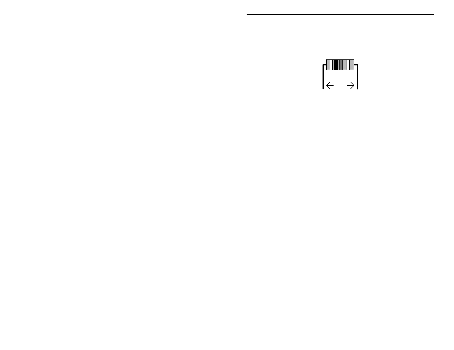
The front-panel controls (tuning, squelch, volume) are mounted next. Before
installing these parts, inspect the type of potentiometer supplied with your kit. If
the pins are located on the front side of the pot, use the front set of mounting
holes on the PC board for installation. If the pins are on the rear, use the rear
set of mounting holes (see below). Also, using side cutters, remove the key tab
from the side of each pot prior to installation.
Rear pins use rear holes.
Nip off tab.
Locate the two (2) 10K potentiometers (B103).
! ! Install a 10K pot at R6 (tuning) and solder.
! ! Install a 10K pot at R16 (volume) and solder.
! ! Find the 100K pot (B104). Install at R10 (squelch) and solder.
Find the radio's oscillator coil (two pins, shielded, red plastic form). Before
installing, confirm that the coil's two pins and shield-can tabs are straight and
aligned with the mounting holes at L4.
! ! Install the oscillator coil at L4 and bend shield-can tabs over. Solder in
place.
Find the quadrature-detector coil (five pins, shielded, with black coil form).
Before installing, make sure all pins and tabs are straight and aligned with
mounting holes at L5.
! ! Install the quad-coil at L5 and bend shield-can tabs over. Solder in place.
Front pins use front holes.
Nip off tab.
13
Page 14

VEC-1012K Owner’s Manual
The last three coils in your radio are hand-wound from the #24 wire supplied. In
addition to the #24 wire, you'll also need a 6-32 screw at least 1/2" long to use as
a winding form. Before starting, carefully straighten the coil wire by drawing it
over a plastic rounded surface such as a screwdriver handle. Remove any bends
or kinks. Cut two (2) lengths about 6" long each.
! ! Take one length of wire and, while grasping both ends firmly, ca refully
wind four (4) full t ur ns ove r the windi ng fo rm--as sho wn below. The wire
should conform into the thread grooves.
4-turns #24 enameled wire
6-32 screw thread
1/2" leads stripped
and tinned with solder
! ! Remove the coil by unscrewing it from the 6-32 threads. Shape the coil as
shown above, with about 1 wire-width spacing between each turn.
Each coil lead must be tinned prior to installation so solder will stick to it. The
wire provided with your kit is coated with enamel insulation formulated to melt
at high temperatures. This quality should allow you to strip, clean, and "tin"
each coil lead in a single operation. To prepare each lead, hold a hot soldering
iron tip against it for several seconds while applying a small amount of solder.
Eventually, the enamel insulation should begin breaking down, allowing solder
to coat and adhere to the wire (it may be easier to perform this operation with the
coil threaded onto the screw). If your soldering iron doesn't generate enough
heat to start the enamel stripping process, scrape the enamel away with an
Exacto knife before tinning. Make sure both leads are clean and brightly
tinned all the way around before attempting to install.
! ! When the first 4-turn coil is prepared as shown, install at L1 and solder.
Check coil shape and spacing before moving on.
! ! Repeat this operation--winding, prepping, installing, and soldering a
second 4-turn coil at L2.
Using the remaining wire, wind a 10-turn coil. Unlike L1 and L2, the turns of
L3 should be compressed together after winding so the overall coil is about .3"
in length--about the distance between its mounting holes.
! ! Wind, prep, and install a 10-turn coil at L3. Solder in place.
14
Page 15

VEC-1012K Owner’s Manual
! ! Install the 9-volt battery snap clip. The red lead is installed at (+ 9V), and
the black at GND. Solder in place.
! ! Stress relief is provided to prevent battery leads from flexing and
eventually breaking at their connection point. Find a hole part-way back
on the left edge of the PC board (not to be confused with the board's
mounting holes at the front and back). Use the plastic tie-wrap provided
in your kit to secure the battery leads in place, as shown below. Insert the
tie-wrap through the hole, close it over the wires, and pul l tight. Nip off
the excess end.
red
+
black
Tie-wrap
SW1
Push-rod
Finally, install receiver ICs U1 and U2. Before doing this, inspect both devices
carefully and straighten any bent or crooked pins. Use extreme care during
insertion, and move slowly. It's very easy to miss a pin opening and fold a IC
pin underneath the body of the device.
Locate U2, the MC34119 audio-amplifier IC (8 pins). Position its keyed (or
notched) end to correspond with the key marked on the pc board at U2.
Carefully align the pins with the U2 mounting holes before inserting.
! ! Install the MC34119 IC at U2, checking carefully that all 8 pins enter
their respective mounting holes. Solder each pin in place.
Locate the MC13135 Receiver IC (24 pins). Position the keyed end to
correspond with the key marked on the pc board at U1. Carefully align the pins
with the U1 mounting holes before inserting.
! ! Install the MC13135 IC at U1 and solder each pin in place.
! ! Inspect the pads under both ICs carefully for solder bridges and cold-
solder (use a magnifying glass, if available). Correcting any problem
before proceeding.
15
Page 16

VEC-1012K Owner’s Manual
This concludes the construction phase of your receiver. You deserve a break!
When you come back, be ready to give your work a thorough "QC" quality
control check before moving on to the testing and alignment section.
16
Page 17

VEC-1012K Owner’s Manual
TESTING AnD ALIGNMENT
PC Board Inspection: Even the most experienced builders make mistakes!
Before applying power to your kit, give it a thorough QC (quality control)
inspection. This will help you find inadvertent assembly errors that might
prevent the radio from working or cause damage to sensitive parts. Follow this
procedure:
1. Compare parts locations against the parts-placement diagram. Was each part
installed where it is supposed to be? Was the correct value used? Start at
one side of the board and work your way across in an organized pattern.
2. Inspect the solder side of the board for cold-solder joins and solder bridges
between tracks or pads. Use a magnifying glass to obtain a clear view of the
track area. If you suspect a solder bridge, hold the board in front of a bright
light for a better view. All joints should be smooth and shiny, indicating
good solder wetting and flow. Resolder any beaded or dull-appearing
connections.
3. Finally, check all electrolytic capacitors and diodes for correct polarity.
Does the plus (+) polarity symbol on the part agree with the pictorial and
with the silk-screen pattern on the PC board? Is the banded end of each
diode positioned correctly? Also, were your ICs installed so the dot or notch
on the plastic case corresponds with the white dot or marking on the PC
board? Was Q1 installed correctly?
Be sure to correct all errors before moving on. If a careful inspection revealed
that everything is OK , you're now ready for t he moment of truth!
Initial Checkout:
To check out your kit you'll need a 9-volt flat-pack type alkaline battery and a 8ohm extension speaker (or monaural headphones) outfitted with a 3.5 mm mini
plug. Make sure the radio's power switch is OFF (button out) before loading the
battery. Plug in speaker or phones and turn all potentiometer controls fully
counter-clockwise.
1. Apply power (button in).
2. Turn up VOLUME (right-hand pot) clockwise. You should hear a rushing
sound, indicating the receiver and audio amplifier are functioning properly.
3. Slowly advance the SQUELCH (center pot) clockwise. The rushing sound
should stop abruptly around mid-range, indicating the squelch circuit is
working.
If your radio p a ssed its tur n-on t est , c ongr a tula tio ns! Y ou'r e well o n your way to
success, and ready for pre-alignment.
17
Page 18

VEC-1012K Owner’s Manual
If your radio didn't pass the turn-on test, don't despair. Odds are, you've
overlooked something minor that's easy to correct. Take a break, come back
fresh, and carefully repeat the QC inspection. If no undiscovered errors turn up
during your second inspection, proceed to the "In Case of Difficulty" section of
this manual for troubleshooting advice.
Pre-Alignment:
You'll need the following items to adjust your receiver:
• 6-32 screw, at least 3/4" long, to check the shaping of L1, L2.
• Insulated hex-head tuning wand to adjust L4.
• Small flat-blade screwdriver or tuni ng wand t o adjust L5.
• Voltmeter, digital or analog, to adjust L5.
• Antenna to receive off-air signals.
The instructions below describe how to pre-adjust each of the radio's coils for a
ballpark setting. This procedure will make final alignment easier.
1. Locate coils L1 and L2. Thread a 6-32 screw inside the windings of each
coil to check for sizing and spacing. If each winding conforms to the 6-32
diameter and thread-pitch, the coil is wound correctly. If not, make any
needed adjustments. Spread the turns so they are exactly 1 wire-width apart.
2. Make a small flag from a scrap of tape and install it on the hex-head tuning
wand. This will help you count revolutions as you adjust L4.
3. Locate tunable-oscillator coil L4. Insert the tuning wand and rotate the slug
counter-clockwise so the top surface is perfectly flush with the top of the
metal shield can. Now, watching the tape flag and counting revolutions,
rotate the slug 4 turns clockwise down into the body of the coil.
4. Set your voltmeter range to 10 Volts dc and connect the black (-) lead to a
ground point on the PC board. Locate pin # 17 on U1 (see the following
diagram). This is the test point for adjusting L5.
FL1
U1, MC13135
5. Set all front-panel controls on the radio counter clockwise, install a 9-volt
battery on the battery snap clip, and apply power via the OFF/ON switch. No
antenna should be connected during this test. With power applied, touch the
18
Test Point, 2.3 V
Page 19

VEC-1012K Owner’s Manual
red (+) voltmeter lead to pin #17. Using a small screwdriver, adjust L5 for a
reading of 2.3 volts. No further adjustment will be required.
Final Alignment--Oscillator Coil L4:
If possible, your kit should be mounted in its VEC-1012KC metal cabinet (or
other enclosure) before adjusting L4. The tuning oscillator frequency coverage
may change slightly if you align L4 with the pc board out of the box, then install
it later. There are several ways to calibrate L4 for coverage. Choose the method
most compatible with the tools you have available:
Option 1: Calibrating with a Signal Generator or FM-Service Monitor
Set the generator up as follows:
!
Frequency:..............................154.0 MHz
!
Output Level: .........................10 uV (-90 dBm)
!
Modulation:............................1 kHz tone at 5 kHz FM deviation
Connect the generator output to your kit's antenna jack using a 50-ohm patch
cable. Plug in headphones or external speaker to monitor generator signal.
1. Set TUNE to 154.0 MHz (fully counterclockwise).
2. Set SQUELCH open (fully counter-clockwise).
3. Power the radio and set VOLUME for a comfortable level.
4. Slowly tune L4 back and forth with the insulated tuning tool to locate the 154
MHz test signal.
Your receiver's varactor tuning circuit should now cover approximately 4 MHz
from bottom to top, providing coverage from 154 to 158 MHz. You may alter
the tuning range, if you wish, to cover any 4 MHz segment from 150-154 to 158162 MHz by readjusting L4 accordingly.
Option 2: Calibrating with a Frequency Counter
Your kit's NBFM receiver IC features a buffered test point for measuring
oscillator frequency with a digital counter. Locate this point on the diagram
below:
.
.
19
Page 20

VEC-1012K Owner’s Manual
FL1
U1, MC13135
3
Test Point
Connect Counter Here
FL2
1. Connect the frequency-counter ground lead to a ground point (case or PC
board).
2. Set the TUNE to 154 MHz (fully counter-clockwise) and apply power.
3. Touch counter probe to pin-3 and adjust L4 for a counter reading of 143.3
MHz.
Important Note:
causing a small change in operating frequency when the counter probe is
removed.
Some counters may "load down" the oscillator circuit slightly,
Option 3: Calibrating with a Scanner or 2-Meter Amateur Radio
Transceiver.
With this method, you use a scanner or 2-meter FM ham transceiver to pick up
your receiver's tuning oscillator. The oscillator operates exactly 10.7 MHz
below the actual receive frequency--which happens to land near the 2-meter ham
band. Unlike the counter method, this approach does not load down the
oscillator circuit and provides more accurate alignment. Install a short antenna
on your scanner or 2-M radio to pick up the oscillator signal.
1. Tune your scanner or 2-M radio to 143.3 MHz and position it near the kit.
2. Set TUNE to 154 MHz (fully counter-clockwise) and apply power.
3. Slowly adj ust L4 until the oscillator signal is heard on the scanner at 143.3
MHz.
Option 4: Calibrating with an Off-Air Signal
.
If no other o ption is availab le, you may calibrate L3 usi ng the signal generated
by a local police or public-service base station. To do this, you must know the
station's operating frequency (a scanning directory should provide that
information). Also, the transmitting station should transmit frequently and be
easily identifiable so you can find when tuning. Finally, the radio should be
mounted in its case with the tuning knob installed. Begin by connecting a
speaker (or phones) and an antenna.
1. Set the SQUELCH pot fully counter clockwise (open).
20
Page 21

VEC-1012K Owner’s Manual
2. Apply power and set the VOLUME pot for a comfortable background-noise
level.
3. Adjust the TUNE knob to correspond with the station's assigned operating
frequency.
4. Slowly tune L4 until you receive the station's signal at the correct spot on the
dial.
This approach may require some patience, since the slug-tuning in L4 is quite
touchy.
Aligning L1, L2 for maximum receiver sensitivity:
If coils L1 and L2 were formed and installed according to instructions, your
radio should operate with near-maximum sensitivity and require no further
adjustment. However, if you wish, you may "tweak" these two coils to optimize
performance on weak distant stations. In order to make this adjustment, you'll
need a weak signal source. This could be a 1-uV 156.0 MHz (mid-band) signal
produced by a signal generator, or a weak mid-band off-air signal with audible
background noise present. To adjust, use the blade of a non-metallic tuning
wand or your fingernail to expand or compress the spacing between turns. Note
that adjusting L2 may change the radio's operating frequency slightly. To
compensate for this interaction, readjust TUNE as you make each change to
ensure the signal remains tuned in.
Reduced background hiss and lower distortion indicates an improvement in
signal strength. As you find the best point for each coil, stretch or compress it
permanently into in that position. Don't attempt to adjust L1 and L2 while
tuned to a strong local signal. Use only a weak signal with clearly-audible
background hiss. Note that L3 is non-critical, and requires no adjustment.
When peaked, your kit should render "solid copy" on FM signals of 1-uV or less.
OPERATING INSTRUCTIONS
Tune
156
Squelch
Volume
Power
1
154
23 4
158
21
Page 22

VEC-1012K Owner’s Manual
1. POWER: Push-on/push-off switch turns unit on and off. The VEC-1012K
runs on internal battery power and shouldn't be left ON for extended period
when not in use.
2. TUNE: Electrically tunes receiver oscillator, setting frequency where signals
are received. Tuning range may vary slightly from unit to unit, but should be
approximately 154 to 158 MHz (the frequencies where most public service
and marine activity take place).
3. SQUELCH: Adjusts threshold-point for cutting off receiver background
noise.
4. VOLUME: Adjust audio amplifier gain a comfortable listening level.
Periodically check battery condition:
Operating your radio with a weak battery may lead to unstable tuning (signals
drifting off channel rapidly), weak or distorted audio, and motor boating (a lowfrequency "putt-putt-putt" noise in your speaker or headphones). Your radio
needs a minimum of 7-8 volts in order to work properly.
Antennas:
The VEC-1012K requires an external antenna. For local reception, a 17" length
of wire may work reasonably well. However, for longer-range reception, a lowcost ground-plane or VHF scanner antenna mounted out-of-doors and fed with
coaxial cable provides much better performance. You may purchase one from
Radio Shack or many other sources. Alternatively, you may make your own
"side-mount" vertical dipole using the following diagram:
22
Page 23

VEC-1012K Owner’s Manual
Brass Welding Rod
(threaded on one end)
6-7 Turns RG-58
Mast Clamp
1-1/2" PVC Pipe
34"
12"
TV Mast
IN CASE OF DIFFICULTY
Your kit's design has been thoroughly field tested, and is known to be both
reliable a nd "forgiving" of constructi on errors. If you have difficulty with your
unit, the cause may be something as simple as a broken cable or a dead battery.
In most cases, you will be able to find the cause with some organized
troubleshooting. Begin your search with this checklist of symptoms and cures:
Does not turn on: Check battery condition, snap clip, and power leads. Also,
make sure lead polarity is correct (red to +, black to GND). Make sure power
switch is "on".
Also, squelch may be locked "on" (see following). Check operating vo l tages.
Turns on, does not receive signals: Check antenna, antenna lead, and plug for
shorted or open condition. Also, radio may not pick up signals in metal building
without an outdoor antenna.
Drifts off-frequency rapidly, "motorboats", weak audio: Symptoms of a
weak battery or insufficient operating voltage. Be sure to check battery voltage
"under load" (with the radio turned on).
23
Page 24

VEC-1012K Owner’s Manual
Squelch won't open when control is fully counter-clockwise: Check the
value of the squelch potentiometer. It must be 100K. If a 10K pot is installed at
R10, the squelch won't open.
Poor sensitivity: Look for antenna problems. Also, check condition of L1, L2,
and L3. If they are improperly shaped or if a lead is broken, sensitivity will be
poor.
If these checks fail to uncover the problem, repeat the "QC" check one more
time. Service records show that, for most malfunctioning kits, outright
component failure is relatively rare. In most cases, the culprit is a misplaced
part, reverse-polarized capacitor or diode, or a faulty solder connection!
Voltage Analysis: One effective way to pin-point where a circuit problem
might be is to use voltage analysis. To do this, you'll need a voltmeter-preferably a high-impedance DMM type. Set your meter to the 10-volt dc range
and clip the black (-) test lead to a ground point on the PC board (the frame of
the antenna connector is a good point). Make sure the radio's battery is fresh-the chart readings were made using a 9.0-volt power source. Using the red (+)
lead, check the voltage on each IC pin and compare it against the voltage chart
below. Readings should be within 10-15% of chart value:
MC13135 (U1) MC34119
(U2)
2SC2498
(Q1)
Pin Voltage Pin Voltage Pin Voltage E B C
1 5.2 13 5.2 1 0.1* .77 7.1
2 4.5 14 0.1* 2 4.0
3 4.3 15 0.1* 3 4.0
4 5.2 16 0 4 4.0
5 4.7 17 2.3 5 4.0
6 5.2 18 5.2 6 8.8
7 3.8 19 5.2 7 0
8 0 20 4.0 8 4.0
9 4.4 21 5.2
10 4.4 22 5.2
11 4.4 23 1.2-3.0
12 .2
*Squelch open voltage (becomes 3.8 when squelch is "logic-high" or closed)
(no sig)
24 0
If you find one or more pins that read radically different from the chart value, it
may indicate the device is bad--or it may mean a circuit problem exists in that
portion of the radio. If you have technical skills and can read a schematic
diagram, this will help you. For example, if you get an unreasonable reading on
24
Page 25

VEC-1012K Owner’s Manual
pin 23 of U1, the schematic shows that the radio's voltage-tuning circuitry is
connected here. You might look for defective or misplaced components on that
portion of the circuit board as a potential cause. If, despite your best effort, you
cannot solve a problem with your radio, kit repair services are ava i lable through
Vectronics. See the warranty on the inside front cover for complete
instructions.
THEORY OF OPERATION AND SPECIFICATIONS
Technical Circuit Description:
The VEC-1012K FM receiver is a sensitive voltage-tunable dual-conversion
NBFM receiver that includes an effective squelch circuit and gated AF-amplifier
IC for speaker o peratio n. Incoming signals are filtered through a bandp ass filter
at L1/L2 to reduce out-of-band interference, then boosted by low-noise
preamplifier Q1. Q1 is series-matched to the input of U1. U1 is a Motorola
device that perform nearly all receiver functions for the radio. The first LO
(local oscillator) is voltage-tuned by a temperature-compensated varactor diode
built into the receiver chip. Signals are converted in the receiver's DBM 1stmixer stage down to 10 .7 MHz, the radio's 1st -IF. Here, t hey are fed through a
roofing filter (FL1) to reduce in-band interference. The second LO, crystalcontrolled at 10.245 MHz, drives the 2nd mixer for converting signals to 455
kHz. FL2 establishes the radio's message-channel bandwidth prior to 100-dB of
signal amplification and limiting in the 2nd IF. Signals are demodulated by
quadrature detection, and recovered audio signals are preamplified to line level
by U1's output stage. Audio is then sent to the receiver's volume control and to
AF amplifier U2.
In addition to pro cessing FM signals, U1 also measures signal strength through
log-amp RSSI circuitry. RSSI output is sent to a built-in op-amp comparator,
where signal strength is compared to a reference level set by the radio's squelch
control. The comparator then generates a logic signal to operate the "mute" pin
of audio amplifier U2 for squelch action.
Audio is supplied to U2 via the radio's volume control. Here, audio signals are
contoured for frequency response and amplified to speaker-level. The output of
U2 is fed to a speaker/phone jack.
Specifications:
Tuning Range................................... 154-158 MHz (may be altered by retuning)
25
Page 26

VEC-1012K Owner’s Manual
Sensitivity......................................... .5 uV typical for usable signal
Selectivity......................................... 20 kHz message-channel bandwidth
AF Output......................................... 60 mW into 8-ohm load
Current Drain.................................... 15 mA squelched, 40 mA on voice peaks
Power Source.................................... 9V flatpack battery
26
Page 27

SCHEMATIC
VEC-1012K Owner’s Manual
27
Page 28

VEC-1012K Owner’s Manual
ENCLOSURE
28
Page 29

VEC-1012K Owner’s Manual
29
 Loading...