

Page 1

IMPORTANT WARRANTY INFORMATION! PLEASE READ
Return Policy on Kits When Not Purchased Directly From Vectronics: Before continuing
any further with your VEC kit check with your Dealer about their return policy. If your Dealer
allows returns, your kit must be returned before you begin construction.
Return Policy on Kits When Purchased Directly From Vectronics: Your VEC kit may be
returned to the factory in its pre-assembled condition only. The reason for this stipulation is,
once you begin i nsta lli ng a nd sol deri ng pa rt s, you essenti al ly tak e over the rol e of the devic e's
manufacturer . From this point on, neither Vect ronics nor its dea lers can reas onably be held
accountab le for the qua lity or the outcome of your work. Because of this, Vectronics cannot
accept return of any kit-in-progress or completed work as a warranty item for any reason
whatsoever. If you are a new or inexperienced kit b uilder, we urge you to read the manual
carefully a nd determine whether or not you're r eady to tak e on the job. If you wish to c hange
your mind and return your ki t, you may--b ut you must do i t before you begin c ons tr uc ti on, a nd
within ten (10) working days of the time it arrives.
Vectronics Warrants: Your kit contains each item specified in the parts list.
Missing Parts: If you determine, during your pre-construction inventory, that any part is
missing, please contact Vectronics and we'll send the missing item to you free of charge.
However, before you contact Vect ronic s, please look carefully to c onf ir m you haven't misr ea d
the marking on one of the other items provided with the kit. Also, make certain an alternative
part hasn't been substituted for the item you're missing. If a specific part is no longer
available, or if Engineering has determined that an alternative component is more suitable,
Vectronics reserves the right to make substitutions at any time. In most cases, these changes
will be clearly noted in an addendum to the manual.
Defective Parts: Today's electronic parts are physically and electrically resilient, and
defective components a re r a re. However, if you disc over a n it em duri ng your pr e- c onst r uct i on
inventory that's obviously broken or unserviceable, we'll replace it. Just return the part to
Vectronics at the address below accompanied with an explanation. Upon receipt, we'll test it.
If it's defec tive and appear s unused, we'll ship you a new one right away at no charge.
Missing or Defective Parts After You Begin Assembly: Parts and materials lost or
damaged after construction begins are not covered under the terms of this warranty. However,
most parts supplied with VEC kits are relatively inexpensive and Vectronics can replace them
for a reasonable charge. Simply contact the factory with a complete description. We'll
process your order quickly and get you back on trac k.
Factory Repair After You Begin Assembly: Kits-in progress and completed kits are
specifically excluded from coverage by the Vectronics warranty. However, as a service to
customers, tec hnicia ns ar e availa ble t o evaluate a nd repai r malf unctioni ng kits for a minimum
service fee of $18.00 (½ hour rate) plus $7.00 shipping and handling (prices subject to
change). To qualify for repair service, your kit must be fully completed, unmodified, and the
printed circuit board assembled using rosin-core solder. In the event your repair will require
more than an hour to fi x (or $36.00, subject to change), our technicians will contact you in
advance by telephone b efore p erforming t he work. Def ective unit s should b e shipp ed prep aid
to:
Vectronics
1007 HWY 25 South
Starkville, MS 39759
Page 2

When shipping, pack your kit well and include the minimum payment plus shipping and
handling charges ($25.00 total). No work can be performed without pre-payment. Also,
provide a valid UPS return address a nd a day time phone number where you may be reac hed.
Page 3

VEC-1002K Owner's Manual 2 Meter FM Receiver Kit
INTRODUCTION
If you ever wanted to get into ham radio, here's the perfect way to get started!
Building the VEC-1002K is a great "hands-on" way to acquire important
technical and radio-communication skills you'll need as a radio amateur. For
example, you'll discover how to identify common electronic components and
read their electrical values. You'll learn how to read pictorial diagrams and
install parts on a printed circuit board. Plus, you'll have the satisfaction of
knowing you built it yourself! Detailed step-by-step assembly instructions guide
you through each stage of construction, and clearly-presented alignment
procedures ensure top performance without need for expensive test equipment.
Once construction is complete, you'll enjoy countless hours listening as licensed
operators communicate 100 miles or more using FM-repeater stations.
According to training experts, monitoring VHF repeater activity before you get
your license helps you learn "ham lingo" and master radio procedures while you
study for your test. Liste ning also introduces you to o ther radio enthusiasts in
your community--and helps you to stay motivated while hitting the books. Best
of all, once the license arrives, you'll conquer mike fright easily because you'll
know exactly what to say!
When it comes to pulling in weak signals, the VEC-1002K rivals many
commercially-built transceivers. In addition, its electronic tuning control covers
only those frequencies where FM repeaters operate. And, just like a professional
transceiver, the VEC-1002K gives you a highly-effective adjustable squelch to
eliminate background noise between transmissions. The VEC-1002K consumes
minimal electrical current and can run for many hours from its self-contained 9volt flat-pack alkaline battery. Plug in a 8-ohm speaker or use headphones for
loud-and-clear reception. All circuitry is self-contained on a rugged 3 " x 3.2 " pc
board.
TOOLS AND SUPPLIES
Construction Area:
area where you can easily organize and handle small parts without losing them.
An inexpensive sheet of white poster board makes an excellent construction
surface, while providing protection for the underlying table or desk. Welldiffused overhead lighting is a plus, and a supplemental high-intensity desk lamp
will prove especially helpful for close-up work. Safety is an important
consideration. Be sure to use a suitable high-temperature stand for your
soldering iron, and keep the work area free of combustible clutter.
Kit construction requires a clean, smooth, and well-lighted
1
Page 4

VEC-1002K Owner's Manual 2 Meter FM Receiver Kit
Universal Kit-building Tools:
additional items to complete, virtually all construction projects require a work
area outfitted with the following tools and supplies:
!
30 to 60 Watt Soldering Iron
!
High-temperature Iron Holder with Moist Cleaning Sponge
!
Rosin-core Solder (thin wire-size preferred)
!
Needle Nose Pliers or Surgical Hemostats
!
Diagonal Cutters or "Nippy Cutters"
!
Solder Sucker, Vacuum Pump, or Desoldering Braid
!
Bright Desk Lamp
!
Magnifying Glass
Special tool for this kit:
!
6-32 screw, at least 3/4" long, for winding coils.
!
Insulated hex-head tuning wand.
!
Small flat-blade screwdriver or t uning wand.
!
Voltmeter, digital or analog.
!
Two-meter antenna to receive off-air signals.
Although your particular kit may require
BEFORE YOU START BUILDING
Experience shows there are four common mistakes builders make. Avoid these,
and your kit will probably work on the first try! Here's what they are:
1. Installing the Wrong Part:
and a 10K resistor may look almost the same, but they may act very
differently in an electronic circuit! Same for capacitors--a device marked
102 (or .001 uF) may have very different operating characteristics from one
marked 103 (or .01uF).
2. Installing Parts Backwards:
capacitors to make sure the positive (+) lead goes in the (+) hole on the
circuit board. Transistors have a flat side or emitter tab to help you identify
the correct mounting position. ICs have a notch or dot at one end indicating
the correct direction of insertion. Diodes have a banded end indicating
correct polarity. Always double-check--especially before applying power to
the circuit!
2
It always pays to double-check each step. A 1K
Always check the polarity of electrolytic
Page 5

VEC-1002K Owner's Manual 2 Meter FM Receiver Kit
3. Faulty Solder Connections:
bridges. Cold solder joints happen when you don't fully heat the connection-or when metallic corrosion and oxide contaminate a component lead or pad.
Solder bridges form when a trail of excess solder shorts pads or tracks
together (see Solder Tips below).
4. Omitting or Misreading a Part:
Always double-check to make sure you completed each step in an assembly
sequence.
Soldering Tips:
professional soldering. Before you install and solder each part, inspect leads or
pins for oxidation. If the metal surface is dull, sand with fine emery paper until
shiny. Also, clean the oxidation and excess solder from the soldering iron tip to
ensure maximum heat transfer. Allow the tip of your iron to contact both the
lead and pad for about one second (count "one-thousand-one") before feeding
solder to the connection. Surfaces must become hot enough for solder to flow
smoothly. Feed solder to the opposite side of the lead from your iron tip--solder
will wick around the lead toward the tip, wetting all exposed surfaces. Apply
solder sparingly, and do not touch solder directly to the hot iron tip to promote
rapid melting.
Desoldering Tips:
these instructions carefully! First, grasp the component with a pair or hemostats
or needle-nose pliers. Heat the pad beneath the lead you intend to extract, and
pull gently. The lead should come out. Repeat for the other lead. Solder may
fill in behind the lead as you extract it--especially if you are working on a
double-sided b o ar d with plat e-thr o ugh hol es. Sho uld this ha pp e n, tr y heat ing the
pad again and inserting a common pin into the hole. Solder won't stick to the
pin's chromium plating. When the pad cools, remove the pin and insert the
correct component. For ICs or multi-pin parts, use desoldering braid to remove
excess solder before attempting to extract the part. Alternatively, a low-cost
vacuum-bulb or spring-loaded solder sucker may be used. Parts damaged or
severely overheated during extraction should be replaced rather than reinstalled.
Cleanliness and good heat distribution are the two secrets of
If you make a mistake and need to remove a part, follow
Inspect for cold solder joints and solder
This is easier to do than you might think!
Work Habits:
instructions and, in many cases, to perform new and unfamiliar tasks. To avoid
making needless mistakes, work for short periods when you're fresh and alert.
Recreational construction projects are more informative and more fun when you
take your time. Enjoy!
Sorting and Reading Resistors:
a color code (shown in the following chart). You don't have to memorize this
code to work with resistors, but you do need to understand how it works:
Kit construction requires the ability to follow detailed
The electrical value of resistors is indicated by
3
Page 6
VEC-1002K Owner's Manual 2 Meter FM Receiver Kit
Resistor Color Code
1st Digit
2nd Digit
Multiplier
Tolerence
(gold or silver)
Black = 0 (tens)
Brown = 1 (hundreds)
Red = 2 (K)
Orange = 3 (10K)
Yellow = 4 (100K)
Green = 5 (1Meg)
Blue = 6
Violet = 7
Gray = 8
White = 9
Silver = 10%
Gold = 5%
When you look at a resistor, check its multiplier code first. Any resistor with a
black multiplier band falls between 10 and 99 ohms in value. Brown designates
a value between 100 and 999 ohms. Red indicates a value from 1000 to 9999
ohms, which is also expressed as 1.0K to 9.9K. An orange multiplier band
designates 10K to 99K, etc. To sort and inventory resistors, first separate them
into groups by multiplier band (make a pile of 10s, 100s, Ks, 10Ks, etc.). Next,
sort each group by specific value (1K, 2.2K, 4.7K, etc.). This procedure makes
the inventory easier, and also makes locating specific parts more convenient later
on during construction. Some builders find it especially helpful to arrange
resistors in ascending order along a strip of double-sided tape.
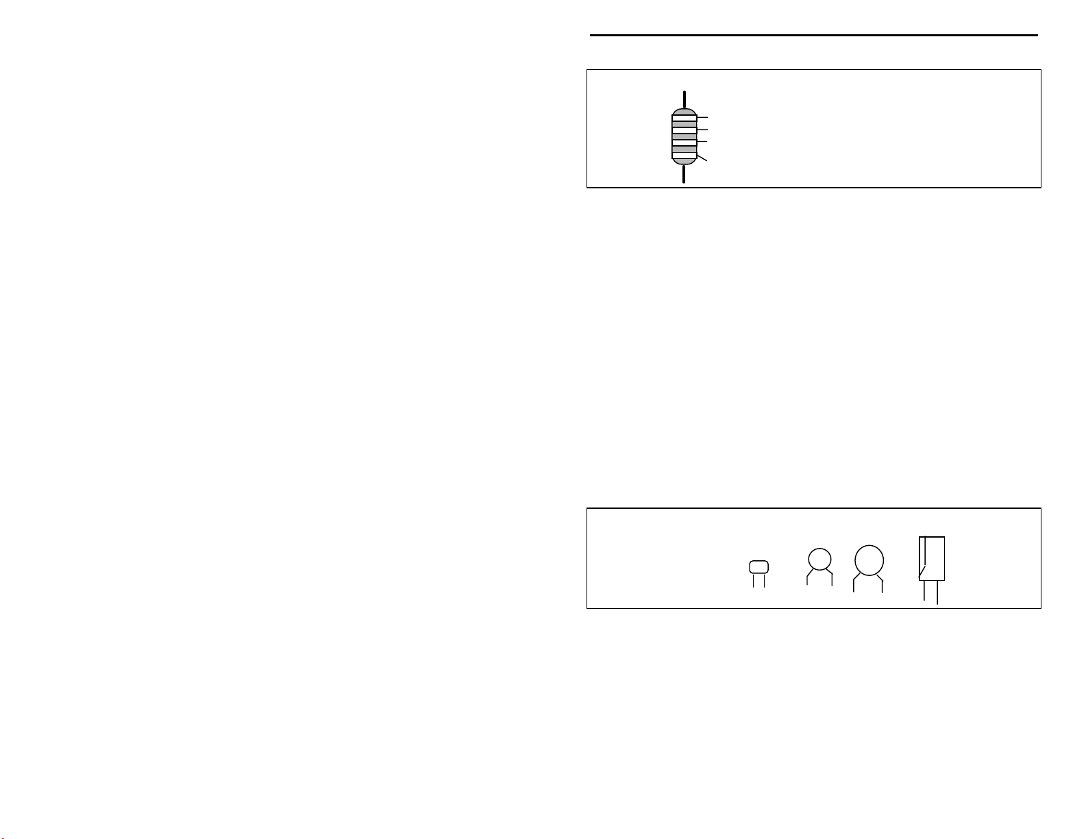
Some VEC kits may contain molded chokes which appear, at first glance, similar
to resistors in both shape and band marking. However, a closer look will enable
you to differentiate between the two--chokes are generally larger in diameter and
fatter at the ends than resistors. When doing your inventory, separate out any
chokes and consult the parts list for specific color-code information.
Reading Capacitors:
Unlike resistors, capacitors no longer use a color code for
value identification. Instead, the value, or a 3-number code, is printed on the
body.
Value Code
10 pF = 100
100 pF = 101
1000 pF = 102
.001 uF = 102*
.01 uF = 103
.1 uF = 104
Multilayer
(270 pF)
271
Ceramic Discs
(.001 uF) (.1 uF)
102
104
Electrolytic
1 uF
1uF
|
35V
|
+
-
As with resistors, it's helpful to sort capacitors by type, and then to arrange them
in ascending order of value. Small-value capacitors are characterized in pF (or
pico-Farads), while larger values are labeled in uF (or micro-Farads). The
transition from pF to uF occurs at 1000 pF (or .001 uF)*. Today, most
monolithic and disc-ceramic capacitors are marked with a three-number code.
The first two digits indicate a numerical value, while the last digit indicates a
multiplier (same as resistors).
Electrolytic capacitors are always marked in uF. Electrolytics are polarized
devices and must be oriented correctly during installation. If you become
4
Page 7
VEC-1002K Owner's Manual 2 Meter FM Receiver Kit
confused by markings on the case, remember the uncut negative lead is slightly
shorter than the positive lead.
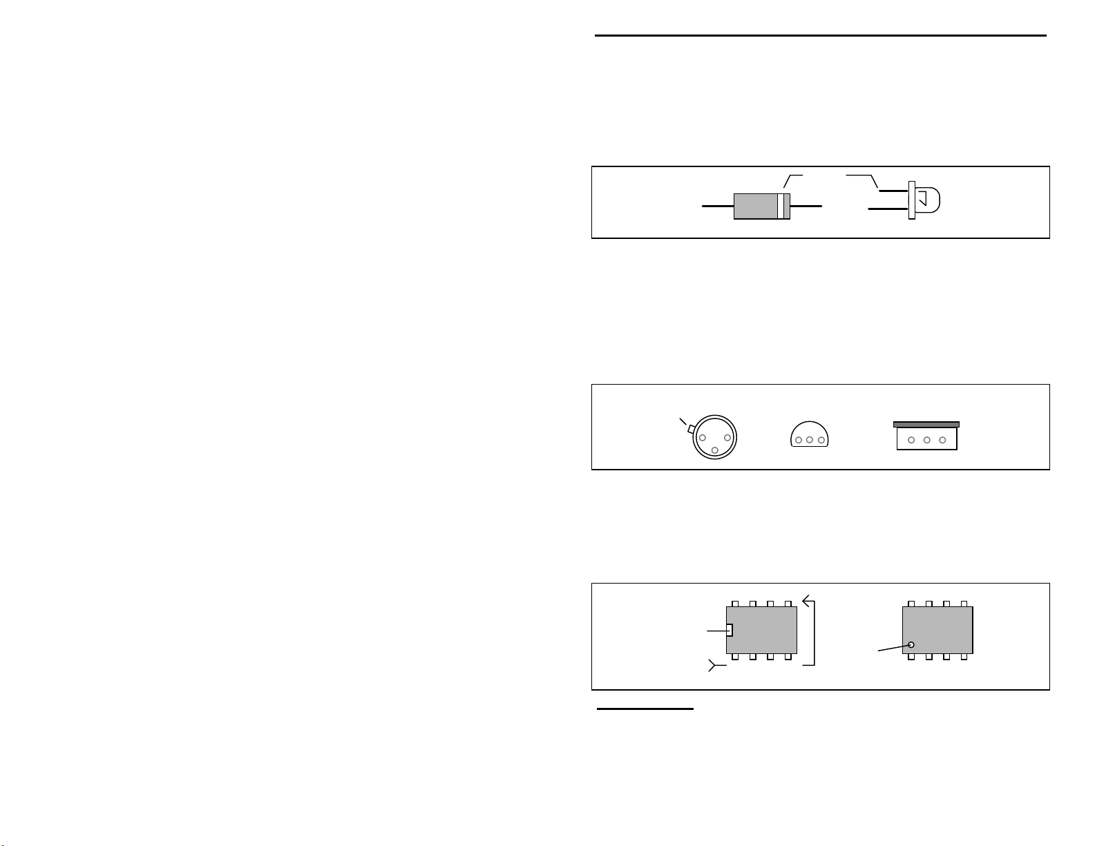
Diodes:
Diodes are also polarized devices that must be installed correctly.
Always look for the banded or cathode end when installing, and follow
instructions carefully.
Cathode
(shorter Lead)
LED
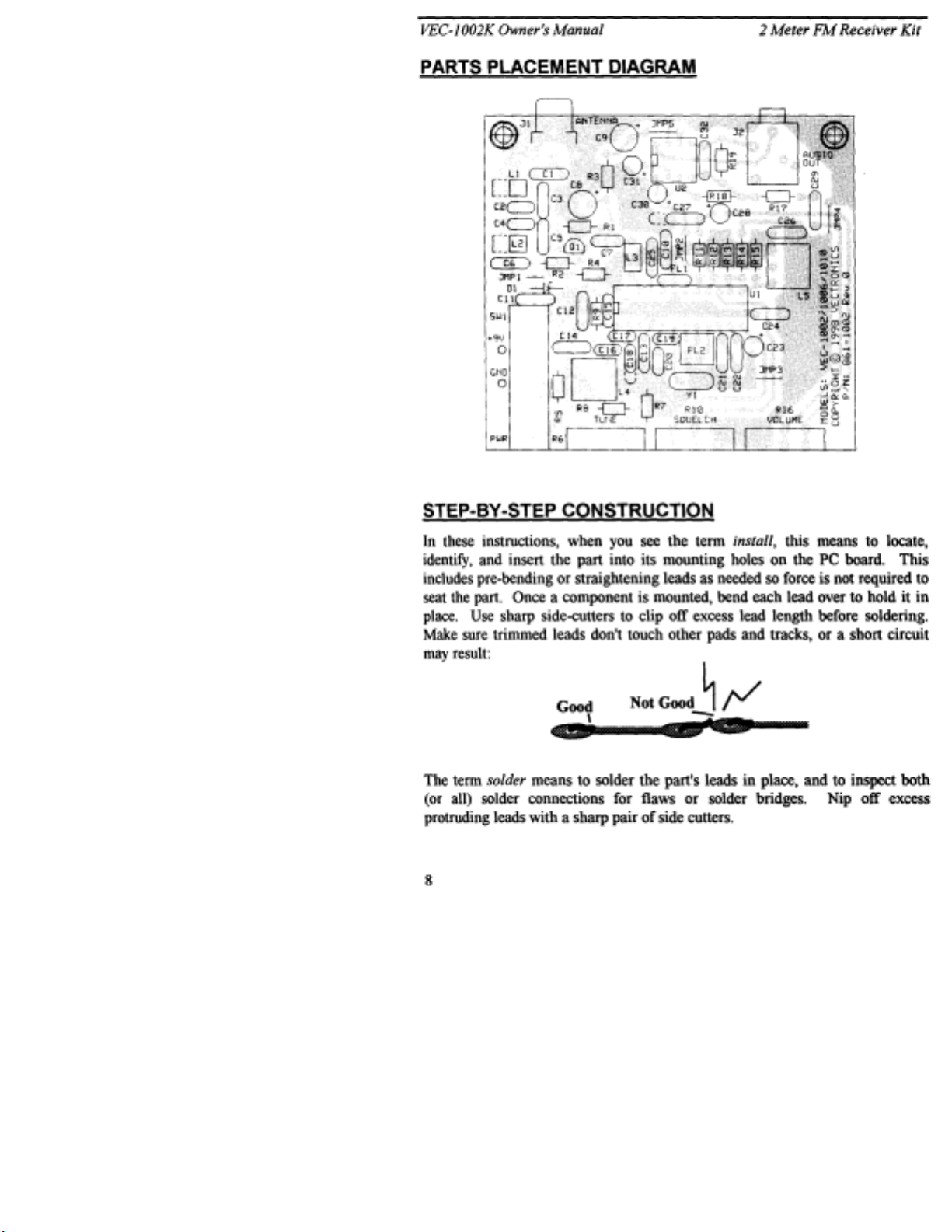
Transistors:
Diode
If transistors are installed incorrectly, damage may result when
power is applied. Transistors in metal cases have a small tab near the emitter
lead to identify correct positioning. Semiconductors housed in small plastic
cases (TO-92) have an easily-identified flat side to identify mounting orientation.
Many specialized diodes and low-current voltage regulators also use this type
packaging. Larger plastic transistors and voltage regulators use a case backed
with a prominent metal tab to dissipate heat (T-220). Here orientation is
indicated by the positioning of the cooling tab.
Metal Can Device Plastic Device Tab-cooled Device
Emitter
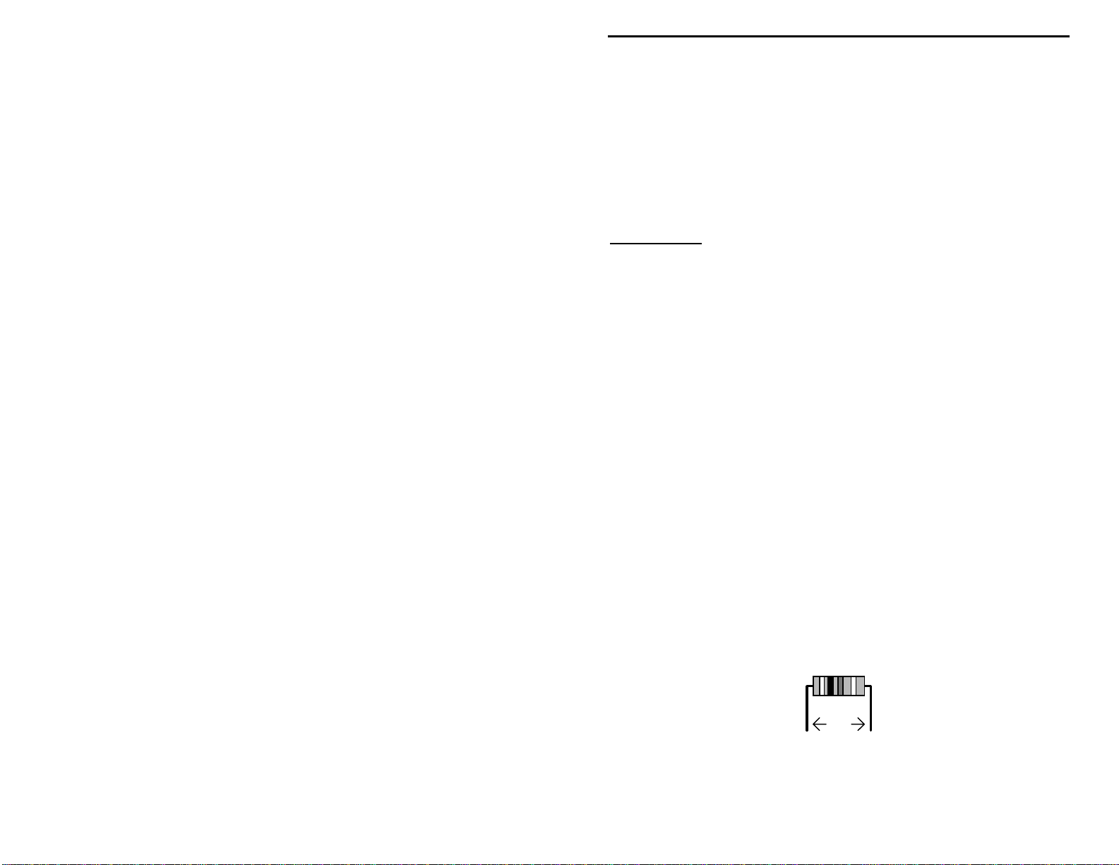
Integrated Circuits:
Flat Side
Proper IC positioning is indicated by a dot or square
Metal Tab
marking located on one end of the device. A corresponding mark will be silkscreened on the PC board and printed on the kit's parts-placement diagram. To
identify specific IC pin numbers for testing purposes, see the diagram below.
Pin numbers always start at the keyed end of the case and progress counterclockwise around the device, as shown:
8 7 6 5
Installation
Key
1 2 3 4
Pin Numbers
Installation
Key
PARTS LIST
Your kit should contain all of the parts listed below. Please identify and
inventory each item on the checklist before you start building. If any parts are
missing or damaged, refer to the manual's warranty section for replacement
5
Page 8

VEC-1002K Owner's Manual 2 Meter FM Receiver Kit
instructions. If you can't positively identify an unfamiliar item on the basis of the
information given, set it aside until all other items are checked off. You may
then be able to identify it by process of elimination. Finally, your kit will go
together more smoothly if parts are organized by type and arranged by value
ahead of time. Use this inventory as an opportunity to sort and arrange parts so
you can identify and find them quickly.
Resistors:
Qty Part Description Designation
"
!
1 22 ohm (red, red, black) R3
!
1 270 ohm (red, violet, brown) R4
!
1 470 ohm (yellow, violet, brown) R2
!
2 2.2K (red, red, red) R11,R14
!
2 4.7K (yellow, violet, red) R7,R17
!
2 10K (brown, black, orange) R5,R18
!
2 39K (orange, white, orange) R12,R15
!
1 47K (yellow, violet, orange) R8
!
4 100K (brown, black, yellow) R1,R9,R13,R19
!
2 10K potentiometer R6,R16
!
1 100K potentiometer R10
Capacitors:
Qty Part Description Designation
"
!
1 2.2 pF disc ceramic (2.2C) C3
!
8 .1 uF disc ceramic (104) C10,C11,C12,C21,C22,
C24,C26,C29
!
1 .05 uF disc ceramic (503) C27
!
1 6.8 pF disc ceramic (6.8J or 6.8C) C5
!
1 4.7 pF disc ceramic (4.7J or 4.7C) C1
!
5 .001 uF disc ceramic (102) C6,C13,C14,C25,C32
!
2 1 uF electrolytic C23,C28
!
2 10 uF electrolytic C30,C31
!
2 100 uF electrolytic C8,C9
!
2 15 pF multilayer (15 or 150) C17,C18
!
1 18 pF multilayer (18 or 180) C19
!
2 27 pF multilayer (27 or 270) C2,C4
Capacitors cont.
Qty Part Description Designation
"
!
1 56 pF multilayer (56 or 560) C20
!
1 100 pF multilayer (101) C7
!
2 470 pF multilayer (471) C15,C16
6
Page 9

VEC-1002K Owner's Manual 2 Meter FM Receiver Kit
Semiconductors:
Qty Part Description Designation
"
!
1 5.1 volt zener diode, 1N751A D1
!
1 2SC2498 transistor Q1
!
1 MC13135 IC (24 pin) U1
!
1 MC34119 IC (8 pin) U2
Inductors/Filters/Crystals
Qty Part Description Designation
"
!
3 12" length of #24 coil wire For L1,L2,L3
!
1 .074 uH slug-tuned, shielded (red) L4
!
1 660 uH adjustable, shielded (black) L5
!
1 10.245 crystal Y1
!
1 10.7 MHz ceramic filter (SFE10.7J) FL1
!
1 455 KHz ceramic filter (55D or 55F) FL2
Switches/Jacks/Misc.
Qty Part Description Designation
"
!
1 DPDT push-button power switch SW1
!
1 RCA phono jack, pc-mounted J1
!
1 3.5mm stereo jack (mini-jack) J2
!
1 8-pin IC socket (for U2)
!
1 24-pin IC socket (for U1)
!
1 9-volt battery snap clip
!
1 plastic cable tie
!
1 PC board for VEC-1002K
!
1 VEC-1002K Owner's Manual
7
Page 10
Page 11
VEC-1002K Owner's Manual 2 Meter FM Receiver Kit
Generally, it's easier to install small close-to-the-board parts first, and then
mount larger stand-up parts second. Delicate parts, such as air-wound coils, go
on the PC board last.
Notice the directions use two sets of check boxes. Check one when a step is
complete and use the other for double-checking your work before operation.
We'll begin with the IC sockets.
Phase 1: IC Sockets
Important Note:
them and mount the ICs directly into the board (an option experienced builders
may prefer). Sockets make IC removal easier in the event of an installation error
or component failure. If you elect to omit the sockets, mount both IC's with their
keyed end toward the left-hand side of the PC board--as indicated by the silkscreen legend.
! !
1. Position the circuit board so J1, J2 and the mounting holes for
If you do not wish to use sockets with your kit, you may omit
integrated circuit U2 are toward the rear. Find the 8-pin IC socket
and, if necessary, straighten any bent pins.
! !
2. Position the 8-pin socket at U2 with its "notch" or " key" toward the
left-hand side of the PC board. Carefully insert the socket (without
soldering).
! !
3. Turn the board over and inspect U2's pads. All 8 socket pins should
protrude through. If any do not, remove the socket, unfold the b ent
pin (or pins), and reinsert. Solder in place.
! !
4. Find the 24-pin IC socket and, using the procedure outlined above,
install at U1 with the key toward the left side of the board. Solder.
! !
5. Inspect the pads under both sockets carefully for solder bridges and
cold-solder joints, correcting any problem areas before moving on.
Phase 2: Resistors
The kit has 16 fixed-value resistors. We'll mount these now, starting with the
smallest value and moving to the largest. Before mounting each one, carefully
bend both leads close to the resistor body to form right-angles, as shown :
.4"
! !
1. Find a 22 ohm resistor (red-red-black). Install at R3 and solder.
! !
2. Find a 270 ohm resistor (red-violet-brown). Install at R4 and solder.
9
Page 12

VEC-1002K Owner's Manual 2 Meter FM Receiver Kit
! !
3. Find a 470 ohm resistor (yellow-violet-brown). Install at R2 and
solder.
! !
4. Find two (2) 2.2K ohm resistors (red-red-red). Install one at R11 and
solder.
! !
5. Install a 2.2K resistor (red-red-red) at R14 and solder.
! !
6. Find two (2) 4.7K resistors (yellow-violet-red). Install one at R7 and
solder.
! !
7. Install a 4.7K resistor (yellow-violet-red) at R17 and solder.
! !
8. Find two (2) 10K resistors (brown-black-orange). Install one at R5
and solder.
! !
9. Install a 10K resistor (brown-black-orange) at R18 and solder.
! !
10. Find two (2) 39K resistors (orange-white-orange). Install one at R12
and solder.
! !
11. Install a 39K resistor (orange-white-orange) at R15 and solder.
! !
12. Find a 47K resistor (yellow-violet-orange). Install at R8 and solder.
! !
13. Find four (4) 100K resistors (brown-black-yellow). Install one at R1
and solder.
! !
14. Install a 100K resistor (brown-black-yellow) at R9 and solder.
! !
15. Install a 100K resistor (brown-black-yellow) at R13 and solder.
! !
16. Install a 100K resistor (brown-black-yellow) at R19 and solder.
This completes installation of the 16 fixed-value resistors (three variable
resistors will be installed later). Take a moment to confirm each one is
positioned in the right location on the PC board.
Phase 3: Disc Ceramic Capacitors
Next, we'll install the kit's 17 disc ceramic capacitors. All capacitors should be
seated as close to the board as possible.
! !
1. Find a 2.2 pF disc ceramic capacitor (2.2). Install at C3 and solder.
! !
2. Find a 4.7 pF disc ceramic capacitor (4.7). Install at C1 and solder.
! !
3. Find a 6.8 pF disc ceramic capacitor (6.8). Install at C5 and solder.
! !
4. Find five (5) .001 uF disc ceramic capacitors (102).
! !
5. Install and solder a .001 uF at C6.
! !
6. Install and solder a .001 uF at C13
10
Page 13

VEC-1002K Owner's Manual 2 Meter FM Receiver Kit
! !
7. Install and solder a .001 uF at C14
! !
8. Install and solder a .001 uF at C25
! !
9. Install and solder a .001 uF at C32
! !
10. Find a .05 uF disc ceramic capacitor (503). Install at C27 and solder.
Two holes are provided on the ground foil side of the cap. Choose the
one that offers best spacing for the capacitor provided in your kit.
! !
11. Find eight (8) .1 uF disc ceramic capacitors (104).
! !
12. Install and solder a .1 uF at C10
! !
13. Install and solder a .1 uF at C11
! !
14. Install and solder a .1 uF at C12
! !
15. Install and solder a .1 uF at C21
! !
16. Install and solder a .1 uF at C22
! !
17. Install and solder a .1 uF at C24
! !
18. Install and solder a .1 uF at C26
! !
19. Install and solder a .1 uF at C29
Phase 4: Multilayer Capacitors
There are 9 multilayer capacitors provided with your kit.
Important Note:
capacitor, except that it has a lead spot-welded onto each end of the capacitor
body. Multilayers have superior operating characteristics, but the lead welds
may fail if the device is over-stressed. For this reason, never use force to seat a
multilayer cap into the PC board. If the spacing isn't right, pre-form the leads to
the correct spacing before installation!
! !
1. Find two (2) 15 pF multilayer capacitors (15 or 150). Install one at
A multilayer capacitor is similar to a surface-mount "chip"
Incorrect
Ooops!
Correct
C17 and solder.
! !
2. Install a a 15 pF multilayer capacitor at C18 and solder.
! !
3. Find a 18 pF multilayer capacitor (18 or 180). Install at C19 and
solder.
11
Page 14

VEC-1002K Owner's Manual 2 Meter FM Receiver Kit
! !
4. Find two (2) 27 pF multilayer capacitors (27 or 270). Install one at C2
and solder.
! !
5. Install a 27 pF multilayer capacitor at C4 and solder.
! !
6. Find a 56 pF multilayer capacitor (56 or 560). Install at C20 and
solder.
! !
7. Find a 100 pF multilayer capacitor (101). Install at C7, spreading the
leads before inserting to accommodate wider pin spacing (this spacing
is due to a PC track running b etween the pads on the bo ttom side of
the board). Solder.
! !
8. Find two (2) 470 pF multilayer capacitors (471). Install one at C15,
spreading the leads for wider spacing (as described above). Solder.
! !
9. Install a 470 pF multilayer capacitor at C16 and solder.
This completes installation of the 9 multilayer caps. Remember to take frequent
breaks while building your kit to avoid fatigue.
Phase 5: Electrolytic Capacitors
The last six (6) capacitors in the kit are electrolytic capacitors.
are polarized and must be installed the correct way in order to work.
capacitor's plus (+) mounting holes are noted on both the circuit board and parts
placement diagram. If the markings on the capacitor body are unclear, the plus
(+) lead is always the longer of the two.
! !
1. Find two (2) 1 uF electrolytic capacitors. Install one at C23, observing
polarity, and solder.
! !
2. Install a 1 uF electrolytic capacitor at C28 and solder.
! !
3. Find two (2) 10 uF electrolytic capacitors. Install one at C30 and
solder.
! !
4. Install a 10 uF electrolytic capacitor at C31 and solder.
! !
5. Find two (2) 100 uF electrolytic capacitors. Install one at C8 and
solder.
! !
6. Solder the remaining 100 uF cap at C9.
This completes installation of all capacitors. Before moving on to the next phase
of construction, check the polarity of each electrolytic one more time to confirm
all six are installed correctly.
Phase 6: Semiconductors
Electrolytic caps
Each
12
Page 15

VEC-1002K Owner's Manual 2 Meter FM Receiver Kit
! !
1. Find the 1N751 zener diode--the only diode supplied with the kit.
Like electrolytic capacitors, zener diodes are polarized and work only
when installed one way. Diode polarity is indicated by the black band
located at one end of the glass body.
! !
2. Install the 1N751 at D1 so the banded end corresponds with the band
marked on the PC board (toward U1). Solder.
! !
3. Locate Q1, a 2SC2498 plastic transistor.
Important Note:
to damage from static discharge. However, if you are working in a carpeted
area, it's always a good practice to touch a metal ground before handling
semiconductors.
! !
4. Note that Q1 has a round and a flat side. Carefully insert the three
Preamp transistor Q1 is a rugged bipolar device with immunity
leads of Q1 into the three mounting holes provided. Make sure that
the transistor body is properly keyed to the silk-screened outline--if
you insert the transistor incorrectly, it may be damaged when power is
applied. To ensure stable preamp operation and best gain, the body of
Q1 should sit as close to the PC board as possible. If needed, gently
pre-form the leads so the bottom of the transistor is positioned
approximately .15" (or 1/8") above the surface of the board. Long
leads may impair performance.
2SC2498
(C2498)
! !
5. Once you're satisfied Q1 is mounted properly, solder in place.
Phase 7: Jumper Wires
Your kit has five (5) jumper wires to install. Each should be pre-formed from a
bare length of discarded component lead, as shown below. The approximate
distance between mounting holes is given to help you pre-form each one. When
installed, each jumper should lay flat against the PC board.
span
discarded lead end
! !
1. Make a jumper with a .2" span. Install at JMP1 and solder.
13
Page 16

VEC-1002K Owner's Manual 2 Meter FM Receiver Kit
! !
2. Make a jumper with a .275" span. Install at JMP2 and solder.
! !
3. Make another jumper with a .275" span. Install at JMP3 and solder.
! !
4. Make a jumper with a .3" span. Install at JMP4 and solder.
! !
5. Make a second jumper with a .3" span. Install at JMP5 and solder.
Congratulations--you've installed most of the "small stuff", and you're well on
the way to completing the kit! Now, we'll begin installing larger and taller
components, and your receiver will take shape more rapidly!
Phase 8: Misce llaneous Items
! !
1. Locate the 10.7 MHz ceramic filter FL1 (10.7J). This device looks
something like a square disc ceramic capacitor with three pins on the
bottom. FL1 is not polarized, and it can be installed either way.
Install and solder in place.
! !
2. Locate the 455 KHz ceramic filter FL2 (55D or 55F). This is a small
black cube with three pins, and it will only fit one way on the PC
board. Install and solder.
! !
3. Find the 3.5 mm stereo mini-headphone jack. Install at J2, making
sure it is fully seated and level. Solder.
! !
4. Find the RCA "phono" type jack. Install at J1, making sure it is fully
seated and level. Solder.
! !
5. Locate push-button power switch SW1. Install and check seating
before soldering.
! !
6. Locate Y1, a 10.245 MHz crystal. Install and solder.
The front-panel controls (tuning, squelch, volume) are mounted next. Before
installing these parts, inspect the type of potentiometer supplied with your kit. If
the pins are located on the front side of the pot, use the front set of mounting
holes on the PC board for installation. If the pins are on the rear, use the rear
set of mounting holes (see following diagram). Also, using sid e cutters, re move
the key tab from the side of each pot prior to installation.
Rear pins use rear holes.
Nip off tab.
Front pins use front holes.
Nip off tab.
14
Page 17
VEC-1002K Owner's Manual 2 Meter FM Receiver Kit
! !
7. Locate two (2) 10K potentiometers. Install one at R6 (tuning), making
sure the pot is firmly seated before soldering in place.
! !
8. Install the second 10K pot at R16 (volume), checking seating before
soldering.
! !
9. Find the 100K pot. Install at R10 (squelch), check seating, and solder.
Phase 9: Coils
! !
1. Find the .074 uH slug-tuned coil with a red form (144-Coilcraft). This
will be installed at L4. Before installing, make sure the coil's two pins
and two shield-can tabs are straight and aligned with the mounting
holes. Install, and bend the shield-can tabs over to hold the can in
place before soldering.
! !
2. Find the 660 uH quadrature detector coil (five pins, black coil form).
Make sure all pins and tabs are straight before installing. Install at L5,
bending over the shield-can tabs before soldering in place.
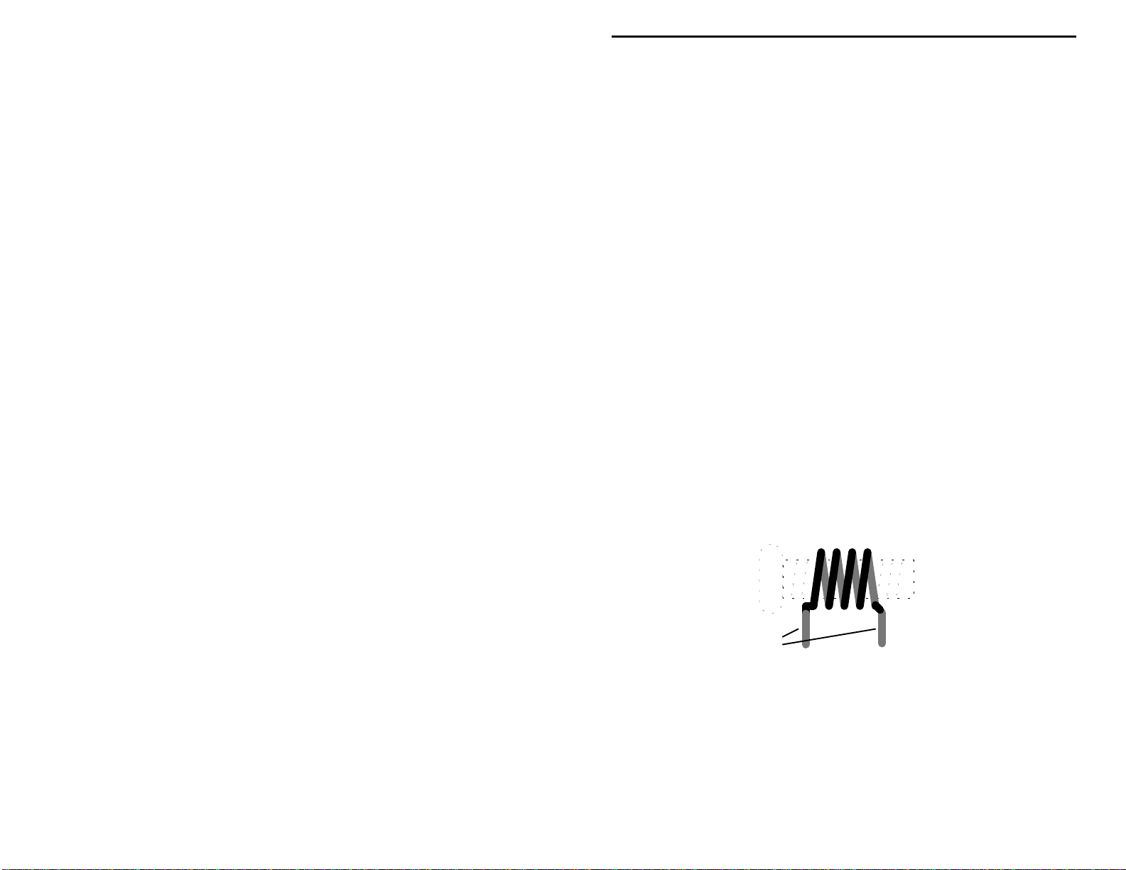
The last three coils in your radio are air-wound types made from the #24 wire
supplied with your kit. In addition to the #24 wire, you'll also need a 6-32 screw
at least 1/2" long to use a s a winding form (longer is better).
! !
3. Carefully straighten the coil wire (drawing it over a plastic rounded
surface such as a screwdriver handle works well). Remove all bends
and kinks. Cut two (2) lengths about 5" long each.
! !
4. Take one length of wire and, while grasping both ends firmly,
carefully wind four (4) full turns over the winding form--as shown.
The wire should conform into the thread grooves.
4-turns #24 enameled wire
6-32 screw thread
1/2" leads stripped
and tinned with solder
! !
5. Remove the coil by unscrewing it from the 6-32 threads. Shape as
shown above, with about 1 wire-width spacing between each turn.
! !
6. Each lead must be tinned prior to installation. The wire provided with
your kit is coated with enamel insulation formulated to melt at high
temperatures. This quality should allow you to strip, clean, and "tin"
each coil lead in a single operation. To prepare each lead, hold a hot
soldering iron tip against it for several seconds while applying a small
15
Page 18
VEC-1002K Owner's Manual 2 Meter FM Receiver Kit
amount of solder. Eventually, the enamel insulation should begin
breaking down, allowing solder to coat and adhere to the wire (it may
be easier to perform this operation with the coil threaded onto the
screw). If your solde ring ir on d oesn't gener ate enough hea t to start the
enamel stripping process, scrape the enamel away with an Exacto
knife before tinning. Make sure both leads are clean and brightly
tinned all the way around before installing.
! !
7. When the first 4-turn coil is prepared as shown, install at L1 and
solder. Check coil shape and spacing before moving on.
! !
8. Repeat the previous operation, installing and soldering a second 4-turn
coil at L2.
! !
9. Using the remaining wire, wind a 10-turn coil for L3. Unlike L1 and
L2, the turns of L3 should be compressed closely so the overall coil is
about .3" in length--about the distance between its mounting holes.
Install and solder.
Phase 10: Completing Construction
! !
1. Install the 9-volt battery snap. The red lead is installed at +9V, and
the black at GND. Solder in place.
! !
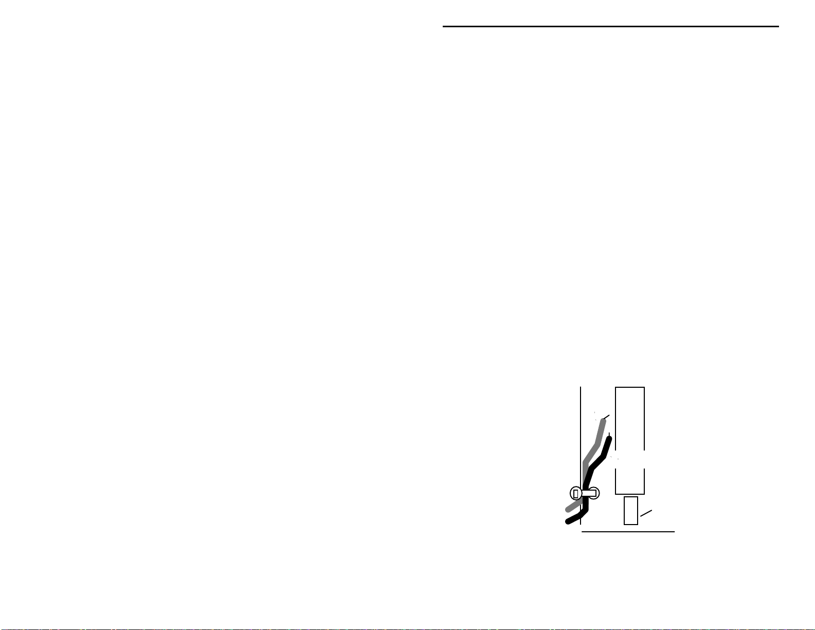
2. Stress relief is provided to prevent battery leads from flexing and
eventually breaking at their connection point. Find a hole part-way
back on the left edge of the PC board Use the plastic tie-wrap
provided in your kit to secure the battery leads in place, as shown in
the following d iagram. Insert the tie -wrap through t he hole, close it
over the wires, and pull tight. Nip off the excess end.
red
+
black
Tie-wrap
SW1
Push-rod
Now, all that remains is to install U1 and U2 in their sockets. Before doing this,
inspect both devices carefully and straighten any bent or crooked pins. Use
16
Page 19

VEC-1002K Owner's Manual 2 Meter FM Receiver Kit
extreme care during insertion, and move slowly. It's very easy to miss a socket
opening and fold a pin underneath the body of the IC.
! !
3. Find U2, a MC34119 8-pin gated audio amplifier IC. Position the
keyed (or notched) end of U2 toward the left side of the board, so it
coincides with the key in the socket. Install, checking carefully that all
8 pins enter their respective socket openings.
! !
4. Repeat the above procedure with U1, the MC13135 24-pin NBFM
dual-conversion receiver IC. The keyed end of this chip also goes
toward the left-hand side of the board, matching the key on the socket.
Install and check pin insertion carefully.
This concludes the construction phase of your receiver. You deserve a break!
When you come back, be ready to give your work a thorough "QC" quality
control check before moving on to the testing and alignment section.
TESTING AND ALIGNMENT
PC Board Inspection:
Even the most experienced builders make mistakes! Before applying power to
your kit, give it a thorough QC (quality contr ol) inspection. This will help you
find inadvertent assembly errors that might prevent the radio from working or
cause damage to sensitive parts. Follow this procedure:
!
Compare parts locations against the parts-placement diagram. Was each
part installed where it is supposed to be? Was the correct value used? Start
at one side of the board and work your way across in an organized pattern.
!
Inspect the solder side of the board for cold-solder joints and solder bridges
between tracks or pads. Use a magnifying glass to obtain a clear view of the
track area. If you suspect a solder bridge, hold the board in front of a bright
light for a better view. All joints should be smooth and shiny, indicating
good solder wetting and flow. Resolder any beaded or dull-appearing
connections.
!
Finally, check all electrolytic capacitors and diodes for correct polarity.
Does the plus (+) polarity symbol on the part agree with the pictorial and
with the silk-screen pattern on the PC board? Is the banded end of each
diode positioned correctly? Also, were your ICs installed so the dot or
notch on the plastic case corresponds with the white dot or marking on the
PC board? Was Q1 installed correctly?
Be sure to correct all errors before moving on. If a careful inspection revealed
that everything is A-OK, you're now ready for the moment of truth!
17
Page 20

VEC-1002K Owner's Manual 2 Meter FM Receiver Kit
Initial Checkout:
To check out your kit you'll need a 9-volt flat-pack type alkaline battery and a 8ohm extension speaker (or monaural headphones) outfitted with a 3.5-mm mini
plug. Make sure the radio's power switch is
battery. Plug in speaker or phones and turn all potentiometer controls fully
counter-clockwise.
1. Apply power (button in).
2. Turn up
sound, indicating the receiver and audio amplifier are functioning properly.
3. Slowly advance the
should stop abruptly around mid-range, indicating the squelch circuit is
working.
If your radio p a ssed its tur n-on t est , c ongr a tula tio ns! Y ou'r e well o n your way to
success, and ready for pre-alignment.
If your radio didn't pass the turn-on test, don't despair. Odds are, you've
overlooked something minor that's easy to correct. Take a break, come back
fresh, and carefully repeat the QC inspection. If no undiscovered errors turn up
during your second inspection, proceed to the "In Case of Difficulty" section of
this manual for troubleshooting advice.
Pre-Alignment:
You'll need the following items to adjust your receiver:
VOLUME
(button out) before loading the
OFF
(right-hand pot) clockwise. You should hear a rushing
SQUELCH
(center pot) clockwise. The rushing sound
•
6-32 screw, at least 3/4" long, to check the shaping of L1, L2.
•
Insulated hex-head tuning wand to adjust L4.
•
Small flat-blade screwdriver or tuning wand t o adjust L5.
•
Voltmeter, digital or analog, to adjust L5.
•
Two-meter antenna to receive off-air signals.
The instructions below describe how to pre-adjust each of the radio's coils for a
ballpark setting. This procedure will make final alignment easier.
1. Make sure the unit is off via the
2. Locate coils L1 and L2. Thread a 6-32 screw inside the windings of each
coil to check for sizing and spacing. If each winding conforms to the 6-32
diameter and thread-pitch, the coil is wound correctly. If not, make any
needed adjustments. Spread the turns so they are exactly 1 wire-width apart.
18
OFF/ON
switch.
Page 21
VEC-1002K Owner's Manual 2 Meter FM Receiver Kit
3. Make a small flag from a scrap of tape and install it on the hex-head tuning
wand. This will help you count revolutions as you adjust L4.
4. Locate tunable-oscillator coil L4. Insert the tuning wand and rotate the slug
counter-clockwise so the top surface is perfectly flush with the top of the
metal shield can. Now, watching the tape flag and counting revolutions,
rotate the slug 6 turns clockwise down into the body of the coil.
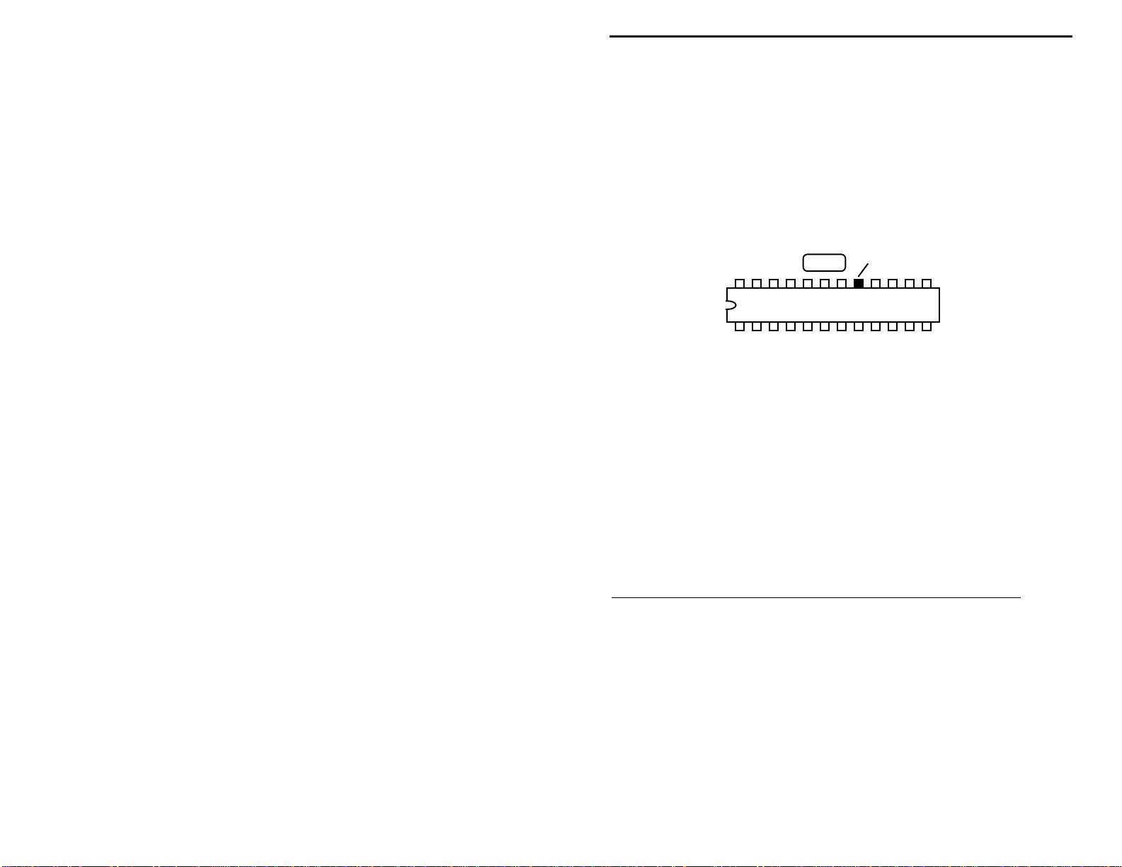
5. Set your voltmeter range to 10 Volts dc and connect the black (-) lead to a
ground point on the PC board. Locate pin # 17 on U1 (see below). This is
the test point for adjusting L5.
FL1
U1, MC13135
6. Set all front-panel controls on the radio counter clockwise, install a 9-volt
battery on the battery snap clip, and apply power via the
No antenna should be connected during this test. With power applied, touch
the red (+) voltmeter lead to pin #17. Using a small screwdriver, adjust L5
for a reading of 2.3 volts. No further adjustment will be required.
Final Alignment--Oscillator Coil L4:
Your kit should be mounted in the VEC-1002KC case for this procedure, with its
knob installed and set to 146.0 MHz. If you don't have a case, set the
TUNE
pot to mid-range (12-o'clock position). Make sure your radio is away
TUNE
from metallic surfaces that could detune it during calibration. Set the PC board
on top of a book if your desk or bench surface is metal. There are several ways
to calibrate your receiver. Choose the method most compatible with the tools
you have availabl e:
OPTION 1: Calibrating with a signal generator or FM-service monitor.
Set the generator up as follows:
•
Frequency: .............................146.0 MHz
•
Output Level:..........................10 uV (-90 dBm)
•
Modulation:............................1-kHz tone at 5-kHz FM deviation
Test Point, 2.3 V
OFF/ON
switch.
Connect the generator output to your VEC-1002K's antenna jack using a 50-ohm
patch cable. Plug in headphones or external speaker to monitor generator signal.
1. Set
2. Power the radio and set
to 146.0 MHz and
TUNE
SQUELCH
VOLUME
counter-clockwise (open).
for a comfortable level.
19
Page 22

VEC-1002K Owner's Manual 2 Meter FM Receiver Kit
3. Slowly tune L4 back and forth with the insulated tuning tool to locate the
146.0 MHz test signal.
OPTION 2: Calibrating with a 2- meter HT.
Set the HT to its lowest power setting and connect a well-shielded 50-ohm
dummy load or a 1/2-watt 47-ohm resistor to the antenna jack. Set the mode
switch for direct operation (no transmit offset). Physically separate the HT from
your VEC-1002K by several feet during the test, and disconnect any external
power cords, speaker-mic cables, etc. that might act as an antenna.
WARNING: Do not, under any circumstance, connect the
output of the HT directly to your VEC-1002K
antenna jack--immediate and serious damage
will result!
Connect a 47-ohm resistor to the VEC-1002K antenna jack, and plug in
headphones or an external speaker--keeping the cord away from the HT.
1. Set
2. Power the radio and set
3. Key the HT's transmit switch. Slowly tune the slug in L4 until the HT signal
is heard.
4. Co nfirm the signal you hear is being gene rated b y the HT (click PT T on and
off).
OPTION 3: Calibrating with a Vectronics or MFJ Antenna Analyzer.
Any Vectronics or MFJ antenna analyzer with VHF coverage may be used to
generate an alignment signal. Set the analyzer to 146.0 MHz and position a few
feet from the VEC-1002K.
to 146.0 MHz and
TUNE
SQUELCH
VOLUME
counter-clockwise (open).
for a comfortable level.
Warning: Do not connect the analyzer directly to your
VEC-1002K, or damage may result.
Install a 47-ohm resistor on the VEC-1002K antenna jack and follow the test
procedure outlined above for alignment using a HT. If your analyzer has a builtin frequency counter, you may also calibrate using the direct-measurement
procedure outlined below (check your analyzer manual for counter operating
instruction).
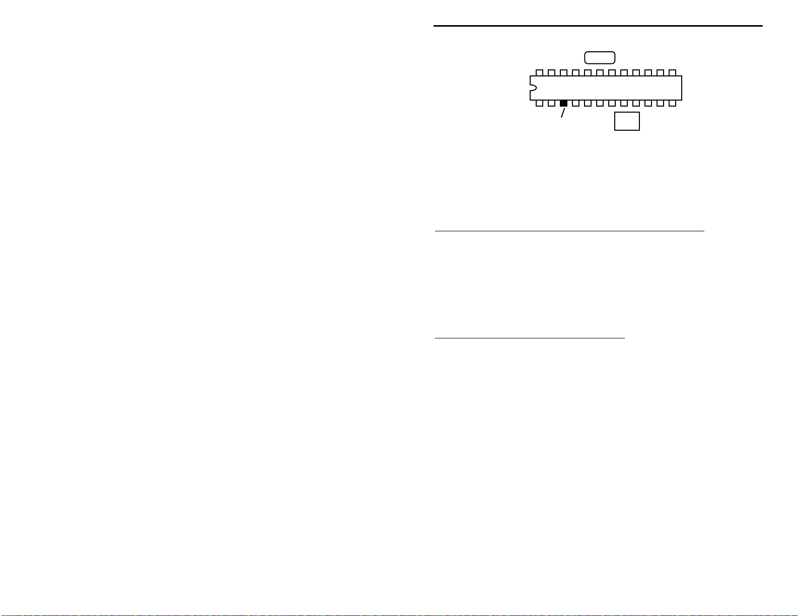
OPTION 4: Calibrating with a frequency counter.
Your VEC-1002K features a buffered test point for measuring oscillator
frequency with a digital counter. Locate this point on the diagram below:
20
Page 23
VEC-1002K Owner's Manual 2 Meter FM Receiver Kit
FL1
U1, MC13135
3
Test Point
Connect Counter Here
1. Connect the frequency-counter ground lead to a ground point (case or PC
board).
2. Set the
3. Touch counter probe to pin 3 and adjust L4 for a counter reading of 135.3
MHz.
OPTION 5: Calibrating with a scanner or extended-coverage HT.
If you don't have access to a counter, you may use a synthesized scanner or
extended-coverage 2-meter HT to pick up the oscillator signal. Set the scanner
to 135.3 MHz and position it near the kit.
1. Set
TUNE
2. Slowly adjust L4 until the oscillator signal is heard on the scanner at 135.3
MHz.
OPTION 6: Calibrating with an off-air signal.
If no other o ption is availab le, you may calibrate L3 usi ng the signal generated
by a local repeater. To do this, you must know the repeater's operating
frequency. Also, the radio should be mounted in its case so the front-panel
tuning-dial scale is available. Begin by connecting a speaker (or phones) and an
antenna.
to 146.0 and apply power.
TUNE
to 146.0 MHz and apply power.
FL2
1. Set the
2. Apply power and set the
3. Adjust the
4. Slowly tune L4 until you receive the repeater's signal at the correct spot on
This approach may require some patience, since the repeater must be active at
the time of your test.
Aligning L1, L2 for Maximum Receiver Sensitivity:
SQUELCH
level.
TUNE
frequency.
the dial.
pot fully counter clockwise (open).
VOLUME
pot to correspond with the repeater's assigned operating
pot for a comfortable background-noise
21
Page 24

VEC-1002K Owner's Manual 2 Meter FM Receiver Kit
If coils L1 and L2 were formed and installed according to instructions, your
radio should operate with near-maximum sensitivity and require no further
adjustment. However, if you wish, you may "tweak" these two coils to optimize
performance on weak distant stations. In order to make this adjustment, you'll
need a weak signal source. This could be a 1 uV 146.0 MHz signal produced by
a signal generator, or a weak off-air signal with audible background noise
present. To adjust, use the blade of a non-metallic tuning wand or your
fingernail to expand or compress the spacing between turns. Note that adjusting
L1 and L2 may change the radio's operating frequency slightly. To compensate
for this interaction, readjust TUNE as you make each change to ensure the signal
remains tuned in.
Reduced background hiss and lower distortion indicates an improvement in
signal strength. As you find the best point for each coil, stretch or compress it
permanently into that position.
to a strong local signal.
background hiss. Note that L3 is non-critical, and requires no adjustment.
When peaked, the VEC-1002K should render "solid copy" on FM signals of 1uV or less.
Don't attempt to adjust L1 and L2 while tuned
Use only a weak signal with clearly-audible
OPERATING INSTRUCTIONS
Tune
Power
1
1.
POWER:
runs on internal battery power and shouldn't be left ON for extended period
when not in use.
2.
TUNE:
are received. Tuning range may vary slightly from unit to unit, but should be
approximately 145.1 to 147.6 MHz (the frequencies where most repeater and
"simplex" FM activity take place).
3.
SQUELCH:
noise.
4.
VOLUME:
Antennas:
22
Push-on/push-off switch turns unit on and off. The VEC-1002K
Electrically tunes receiver oscillator, setting frequency where signals
Adjusts threshold-point for cutting off receiver background
Adjust audio amplifier gain to a comfortable listening level.
146
145
23 4
Squelch Volume
147
VEC-1002K
Page 25

VEC-1002K Owner's Manual 2 Meter FM Receiver Kit
The VEC-1002K requires an external antenna. For local reception, a 19" length
of wire may work reasonably well. However, for longer-range reception, a lowcost 2-meter ground-plane or VHF scanner antenna mounted outdoors and fed
with coaxial cable provides much better performance. You may purchase one
from Tech America, Radio Shack, MFJ Enterprises Inc., and many other
sources. Alternatively, you may make your own "side-mount" vertical dipole
using the following dia gram:
Brass Welding Rod
6-7 Turns RG-58
Mast Clamp
Periodically Check Battery Condition:
Operating your radio with a weak battery may lead to unstable tuning (signals
drifting off channel rapidly), weak or distorted audio, and motor boating (a lowfrequency oscillation or "putt-putt-putt" noise in your speaker or headphones).
Your radio needs a minimum of 7-8 volts in order to work properly.
1-1/2" PVC Pipe
38"
12"
TV Mast
IN CASE OF DIFFICULTY
The VEC-1002K design has been thoroughly field tested, and is known to be
both reli able and " forgiving" of co nstruction err ors. If you have d ifficulty with
your unit, the cause may be something as simple as a broken cable or a dead
battery. In most cases, you will be able to find the cause with some organized
troubleshooting. Begin your search with this checklist of symptoms and cures:
23
Page 26
VEC-1002K Owner's Manual 2 Meter FM Receiver Kit
Does not turn on:
make sure lead polarity is correct (red to +, black to GND). Make sure power
switch is "on".
Also, squelch may be locked "on" (see following). Chec k operating volt ages.
Turns on, does not receive signals:
shorted or open condition. Also, radio may not pick up signals in metal building
without an outdoor antenna.
Drifts off-frequency rapidly, "motorboats", weak audio:
weak battery or insufficient operating voltage. Be sure to check battery voltage
"under load" (with the radio turned on).
Squelch won't open when control is fully counter-clockwise:
value of the squelch potentiometer. It must be 100K. If a 10K pot is installed at
R10, the squelch won't open.
Poor sensitivity:
If they are improperly shaped or if a lead is broken, sensitivity will be poor.
If these checks fail to uncover the problem, repeat the "QC" check one more
time. Service records show that, for most malfunctioning kits, outright
component failure is relatively rare. In most cases, the culprit is a misplaced
part, reverse-polarized capacitor or diode, or a faulty solder connection!
Voltage Analysis:
might be is to use voltage analysis. To do this, you'll need a voltmeter-preferably a high-impedance DMM type. Set your meter to the 10-volt dc range
and clip the black (-) test lead to a ground point on the PC board (the frame of
the antenna connector is a good point). Make sure the radio's battery is fresh-the chart readings were made using a 9.0-volt power source. Using the red (+)
lead, check the voltage on each IC pin and compare it against the voltage chart
below. Readings should be within 10-15% of chart value:
Check battery condition, snap clip, and power leads. Also,
Check antenna, antenna lead, and plug for
Symptoms of a
Check the
Look for antenna problems. Check condition of L1, L2, L3.
One effective way to pin-point where a circuit problem
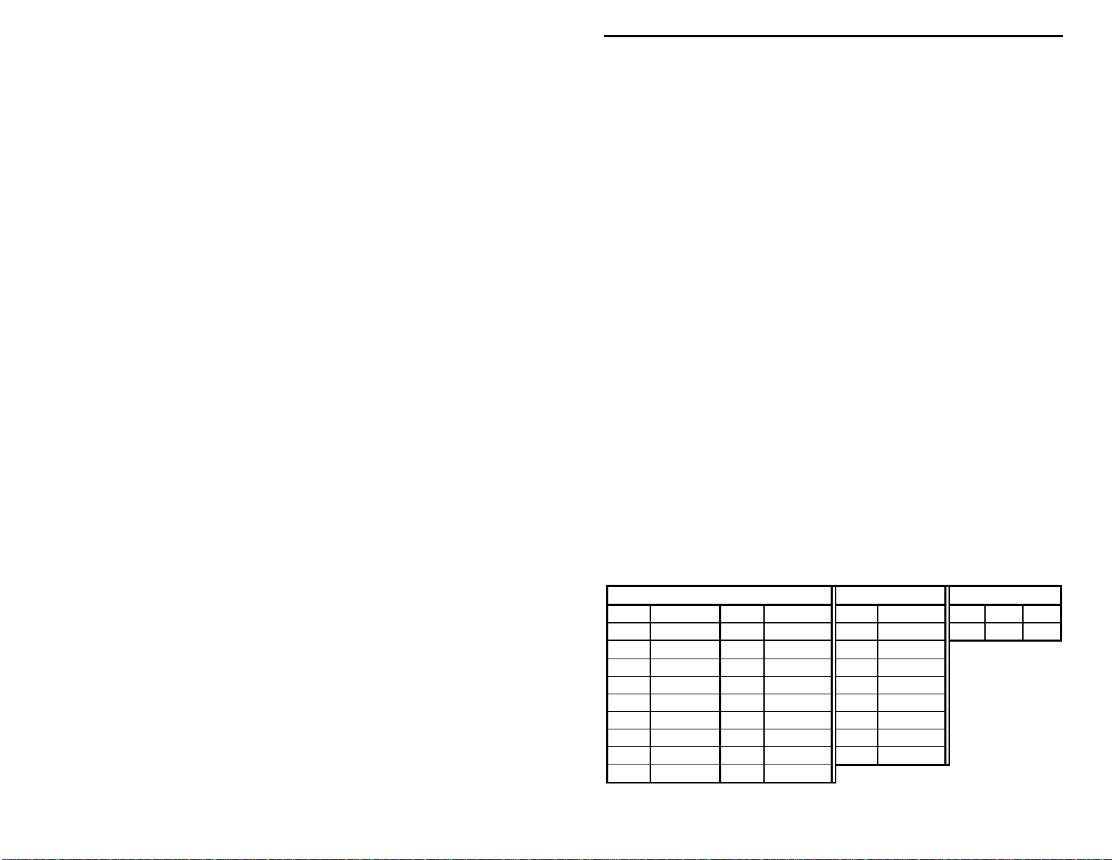
MC13135 (U1) MC34119 (U2) 2SC2498 (Q1)
Pin Voltage Pin Voltage Pin Voltage E B C
1 5.2 13 5.2 1 0.1* .77
2 4.5 14 0.1* 2 4.0
3 4.3 15 0.1* 3 4.0
4 5.2 16 0 4 4.0
5 4.7 17 2.3 5 4.0
6 5.2 18 5.2 6 8.8
7 3.8 19 5.2 7 0
8 0 20 4.0 8 4.0
9 4.4 21 5.2
24
Page 27
VEC-1002K Owner's Manual 2 Meter FM Receiver Kit
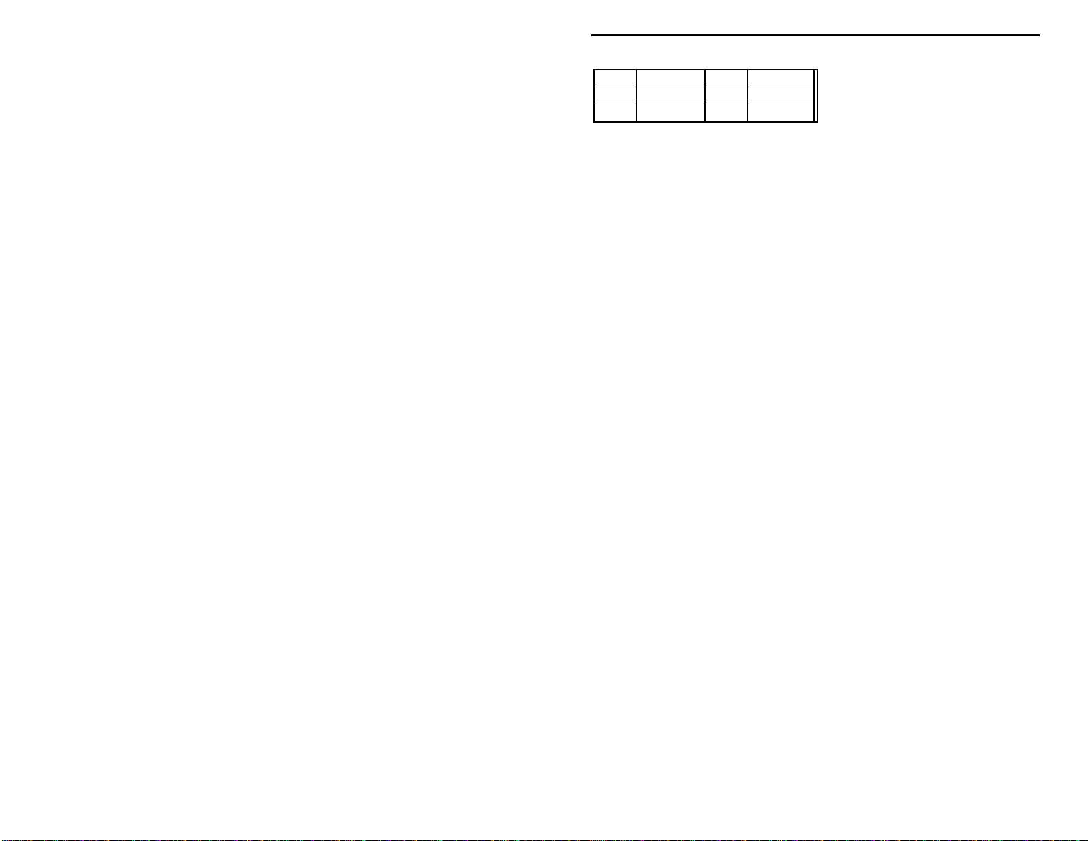
10 4.4 22 5.2
11 4.4 23 1.2-3.0
12 .2
*Squelch open voltage (becomes 3.8 when squelch is "logic-high" or closed)
(no sig)
24 0
If you find one or more pins that read radically different from the chart value, it
may indicate the device is bad--or it may mean a circuit problem exists in that
portion of the radio. If you have technical skills and can read a schematic
diagram, this will help you. For example, if you get an unreasonable reading on
pin 23 of U1, the schematic shows that the radio's voltage-tuning circuitry is
connected here. You might look for defective or misplaced components on that
portion of the circuit board as a po tential cause. If, despite your best effort, you
cannot solve a p r o bl em with your r ad io , ki t r ep ai r se rvi ce s ar e a vail ab le thr ough
Vectronics. See the warranty on the inside front cover for complete
instructions.
25
Page 28

VEC-1002K Owner's Manual 2 Meter FM Receiver Kit
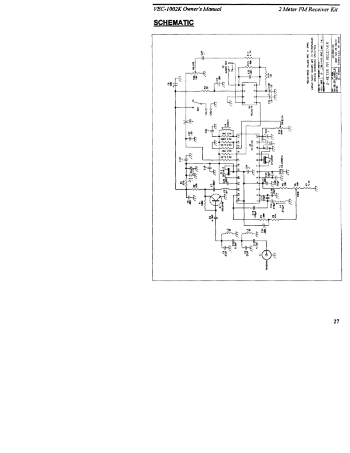
THEORY OF OPERATION AND SPECIFICATIONS
Technical Circuit Description:
The VEC-1002K FM is a sensitive voltage-tunable dual-conversion NBFM
receiver that includes an effective squelch circuit and gated AF-amplifier IC for
speaker operation. Incoming signals are filtered through a bandpass filter at
L1/L2 to reduce out-of-band interference, then boosted by low-noise
preamplifier Q1. Q1 is series-matched to the input of U1.
U1 is a Motorola device that performs nearly all receiver functions for the radio.
The first LO (local oscillator) is voltage-tuned by a temperature-compensated
varactor diode built into the receiver chip. Signals are converted in the receiver's
DBM 1st-mixer stage down to 10.7 MHz, the radio's 1st IF. Here, they are fed
through a roofing filter ( FL1) to reduce in-band interfere nce. The second LO,
crystal-controlled at 10.245 MHz, drives the 2nd mixer for converting signals to
455 KHz. FL2 establishes the radio's message-channel bandwidth prior to 100dB of signal amplification and limiting in the 2nd IF. Signals are demodulated
by quadrature detection, and recovered audio signals are preamplified to line
level by U1's output stage. Audio is then sent to the receiver's volume control
and to AF amplifier U2.
In addition to pro cessing FM signals, U1 also measures signal strength through
log-amp RSSI circuitry. RSSI output is sent to a built-in op-amp comparator,
where signal strength is compared to a reference level set by the radio's squelch
control. The comparator then generates a logic signal to operate the "mute" pin
of audio amplifier U2 for squelch action.
Audio is supplied to U2 via the radio's volume control. Here, audio signals are
contoured for frequency response and amplified to speaker-level. The output of
U2 is fed to a speaker/phone jack.
Specifications:
Tuning Range..................................145.1 - 147.6 MHz (approximate)
Sensitivity.........................................5 uV typical for useful audio recovery
Selectivity........................................20-kHz message-channel bandwidth
AF Output........................................60 mW into 8-ohm load
Current Drain...................................15 mA squelched, 40 mA on voice peaks
Power Source...................................9 Volt flatpack battery
PCB Size.........................................3.300" x 3.000"
26
Page 29
Page 30

VEC-1002K Owner's Manual 2 Meter FM Receiver Kit
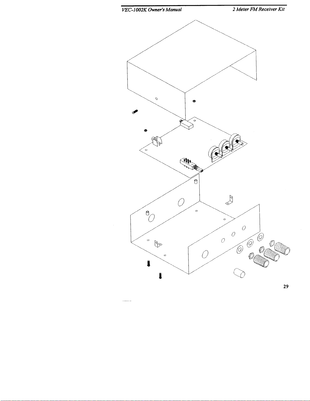
ENCLOSURE
Vectronics has designed a matching enclosure just for your VEC-1002K 2 Meter
FM Receiver Kit. The matching enclosure is an all metal box which includes
knobs, hardware, decals, and rubber feet.
Model: VEC-1000KC.
To install your receiver in the VEC-1000KC matching enclosure follow these
instructions (read
1. Find the front panel decal a nd rear panel dec al; separa te using sci ssors . Be sure to leave
excess deca l material around the edges. Put the rear p anel decal on fir st. This is done
by: a.) Remove all debris and oil f rom the cha ss is. This should be done using a piec e of
cloth and alc ohol. b.) Remove the cra ck and peel t o expose the adhesi ve. c.) Place the
decal on the rear panel without securing it completely. d.) Gently rub the alignment
circles with your finger--if the circles are centered in the enclosure holes (also check the
corner alignment ma rks) s ecure the deca l by rubb ing and removing all air bub bles. e.) If
the alignment circles are not centered, adjust the decal accordingly, then secure. f.) Use a
penknife, or s mall Exacto
side) and cut out the component holes (cut from the description side). g.) Repeat this
procedure for the front panel.
2. Next, insta ll the t wo L- b ra c k ets on t he cha s si s usi ng t wo of t he 3 /1 6 " s c rews . The longer
side of the L-bra cket must be connected t o the chassis us ing the two holes centered on
each edge of the enclosure. Refer to the diagram on the next page for location and
orientation.
3. Install the two 1/2 " mounting screws next . Insert the scr ews, from the bott om, through
the two holes relatively close to each rear corner of the chassis.
4. Plac e the two 3/16" round spacers on the mounting screws.
5. Now insert t he PC boa rd. Thi s must b e done by: a.) Remove the nuts a nd washer s fr om
R6, R10, and R16. b.) Insert the front of the PC board at an angle so t he controls enter
their respec tive holes. c.) P ush down on the rear of the boar d. Make sure the mounting
screws align with the mounting holes in t he PC board befor e pushing.
6. Use the two hex nuts t o secure t he PC boa rd. Be c ertai n all a ppr opria te component s are
centered with the enclosure holes before tightening. Put the washers and nuts--removed
from R6, R10, and R16--back on and tighten.
7. Find the knobs and switch cap. Align the switch cap with SW1 and push it on. If it is
difficult to push on, then rotate it 90° and try again. Now put the knobs on R6, R10, and
R16. You may need to loosen the set screw. Align appropriately then tighten the set
screws.
8. Locate the piece of doubl e-sided tape. This is to be used f or holding the 9-volt b attery
clip in pl ace. Locat e a p lac e on the under side of the top cover where t he ba tter y will not
interfere with any components. Peel off the backing of the tape and stick it to the chosen
location, then install the battery clip.
9. Install the top next. Use the two remaining 3/16" screws for securing the top to the L-
brackets. Make sure t he L-bracket s are aligned properly.
10. Finally, place the four r ubber feet on the b ottom of the enclosure at the corners.
all
instructions before beginning ... take your time):
TM
knife, t o cut awa y the unused edges (cut from the adhesive
28
Page 31
 Loading...