

Page 1

VC-300M Antenna Tuner Owner's Manual
Vectronics VC-300M Antenna Tuner
FEATURES
The Vectronics VC-300M Antenna Tuner optimizes the performance of your antenna and
transmitter, receiver, or transceiver by providing adjustable impedance matching. The
VC-300M also measures the Power and Standing Wave Ratio (SWR), allowing you to
adjust for the lowest possible ratio for the selected transmit frequency. The VC-300M
utilizes a precision frequency compensated lighted dual movement SWR/Power meter
which can show either peak or average readings.
SPECIFICATIONS
FRONT PANEL INDICATORS
Meter ....................................Dual movement lighted cross needle Power and SWR meter.
FRONT PANEL CONTROLS
TRANSMITTER Tuning .....Continuous rotation capacitor
ANTENNA Tuning..............Continuous rotation capacitor
INDUCTANCE....................48 Turn Switched Rotary Inductor
RANGE................................2 position switch: 30W/300W
METER ................................2 position switch: PEAK/AVG
LAMP...................................2 position switch: ON/OFF
REAR PANEL CONNECTORS
INPUT..................................SO-239 Connector
OUTPUT..............................SO-239 Connector
12 V AC/DC.........................2.5 mm Barrel Connector
GROUND.............................Post/Wingnut
OTHER
Frequency Coverage.............1.8-30 MHz
Power....................................150 Watts Continuous; 300 Watts pep, SSB
Dimensions...........................3.6" (92 mm) H x 7.25" (184 mm) W x 8.75" (222 mm) D.
Weight..................................2.5 lbs. (1.15 kg)
1
Page 2
VC-300M Antenna Tuner Owner's Manual
CONTOLS / CONNECTORS
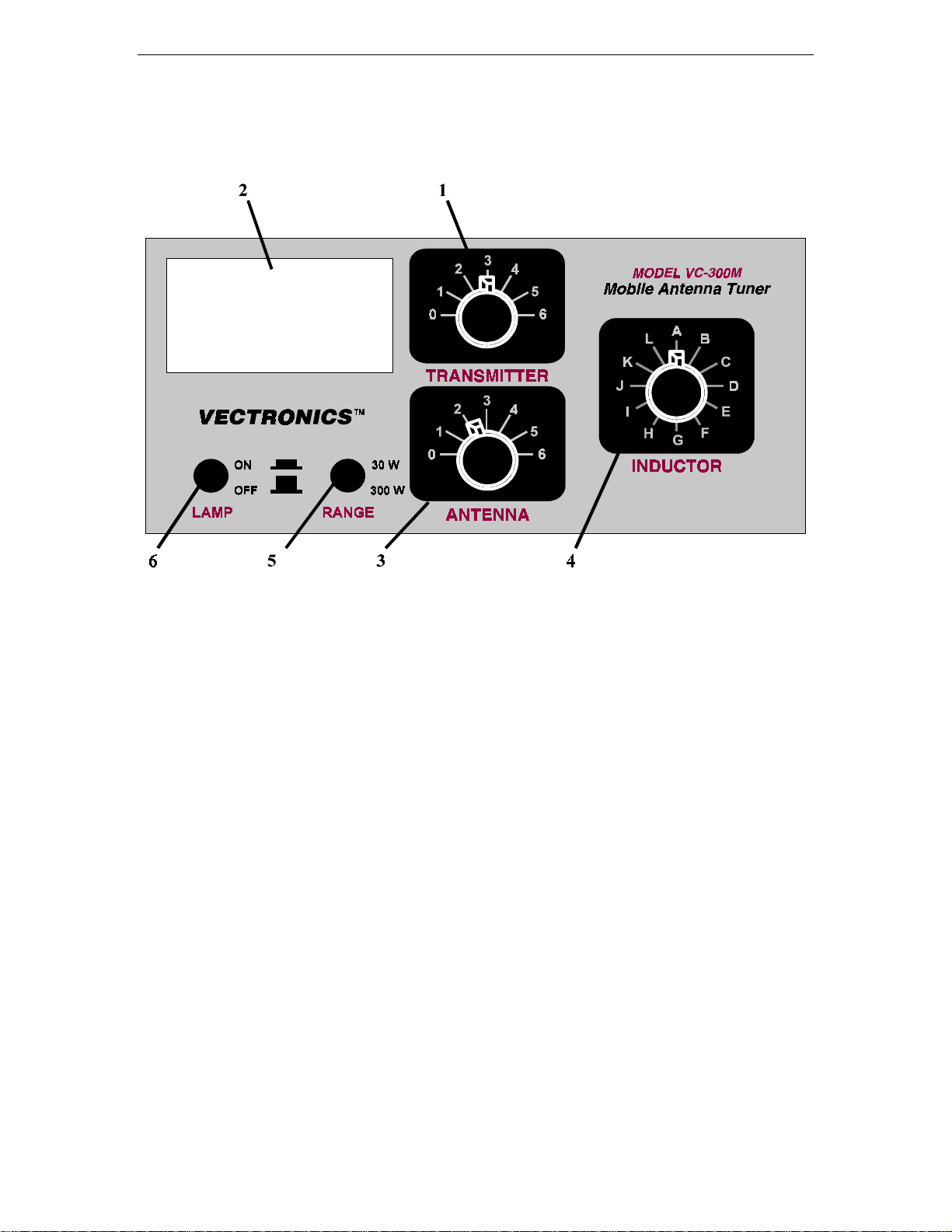
FRONT PANEL FUNCTIONS
1. TRANSMITTER
Continuously adjustable input capacitor
2. POWER / SWR METER
Dual needle meter displays FOWARD and REFLECTED Power in Watts.
The SWR in measured where the two needles intersect on the red scale.
3. ANTENNA
Continuously adjustable output capacitor.
4. INDUCTOR
48-position rotary switch to vary inductance.
5. RANGE
Two-position push button switch selects the range of FOWARD and REFLECTED
Power displayed on the power meter.
When the RANGE switch is OUT, the FOWARD meter scale reads 300 watts full
scale and the REFLECTED meter scale reads 60 watts full scal e. When the switch i s
IN, the FOWARD meter scale reads 30 watts full scale and the REFLECTED meter
scale reads 6 watts full scale.
6. LAMP
Two-position push button switch turns the lamp ON or OFF.
2
Page 3
VC-300M Antenna Tuner Owner's Manual
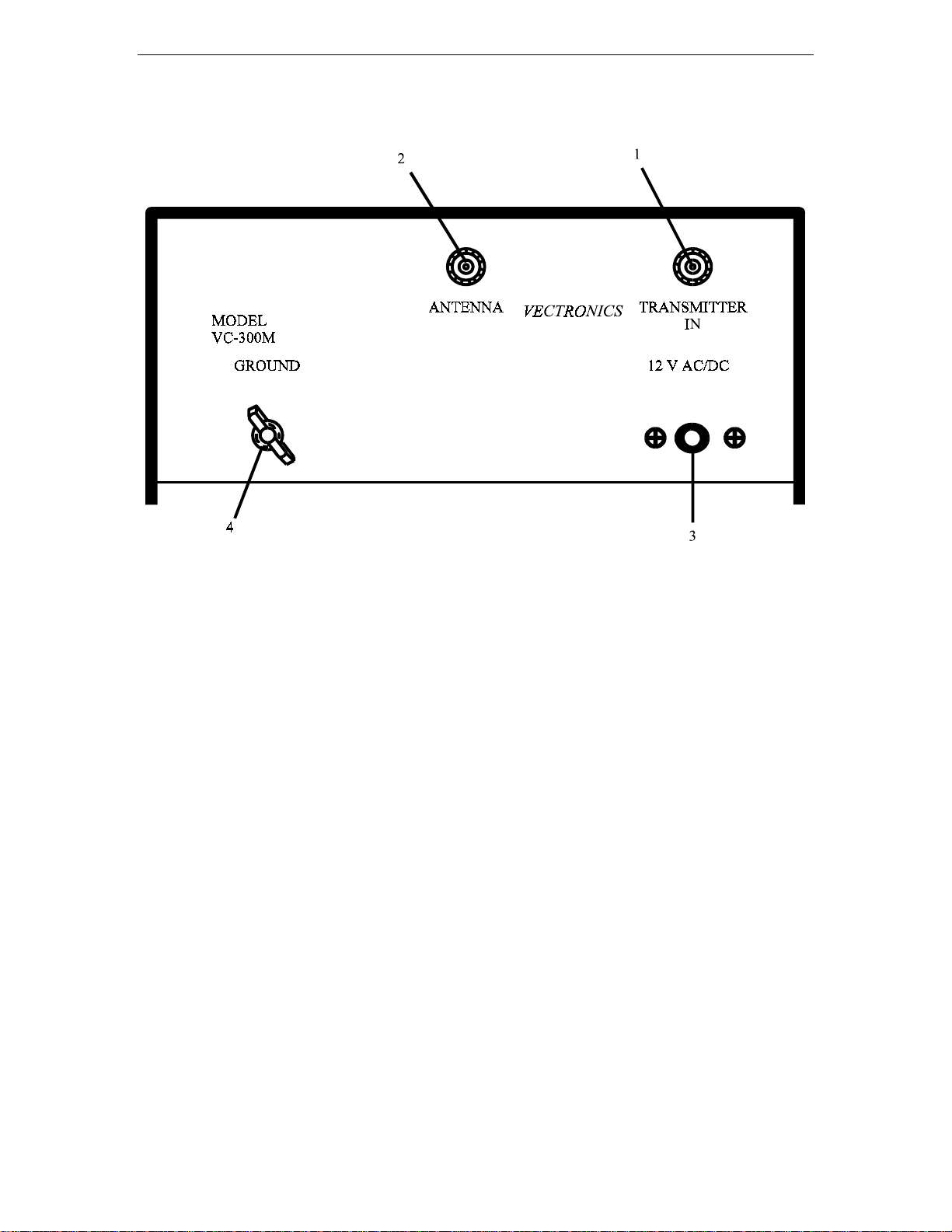
REAR PANEL CONNECTORS
1. TRANSMITTER IN
Coaxial connector for input from SWL receiver or transmitter.
2. ANTENNA
Coaxial connector for output.
3. 12V AC/DC
Barrel connector for meter lamp power.
4. GROUND
Post/Wing-nut type ground connector.
INSTALLATION
Carefully unpack your VC-300M from the packing carton and inspect it for signs of
damage. If any damage is apparent, notify the transportation carrier or dealer
immediately. We recommend keeping the packing carton for moving, storage, or
reshipping the tuner.
Select a location for the VC-300M that allows the connectors to be free of any possible
contact during operation.
3
Page 4

VC-300M Antenna Tuner Owner's Manual
INSTALLATION PROCEDURES
1. Connect a coax cable from your transmitter or receiver to the transmitter to the
TRANSMITTER connector on the rear panel. Keep the cable as short as possible.
Do not use more than 200 watts through the tuner.
2. To avoid possible damage to the VC-300M, set the TRANSMITTER, ANTENNA,
and RANGE switches as outlined in the nest section before applying transmitter
power.
3. Begin tuning with your transmitter set at a low output setting (
10 to 20W)
.
WARNING: Do not operate the VC-300M with the cover off! Do not change the
inductor switch with more than 20 watts of applied power!
TUNING
1. Select the band and frequency of desired operation.
2. Set TRANSMITTER, ANTENNA, and INDUCTOR controls to the suggested
settings before applying transmitter power. Actual settings may vary from antenna to
antenna.
BAND/
FREQUENCY
TRANSMITTER
Sug. Actual Sug. Actual Sug. Actual
160 M / 1.8 MHz 2.8 3.8 J+
75 M / 3.75 MHz 3.0 3.8 D
ANTENNA
INDUCTANCE
40 M / 7.15 MHz 4.5 5.5 B+
30 M / 10.125 MHz 2.8 3.2 B+
20 M / 14.175 MHz 3.5 4.0 A+
17 M / 10.118 MHz 2.0 2.7 A+
15 M / 21.225 MHz 3.0 3.5 A+
12 M / 24.940 MHz 5.5 6.0 A+
10 M / 28.850 MHz 2.8 3.1 A
3. Set up your transmitter to a low power output. If your transmitter has a tune position,
select that position.
4
Page 5

VC-300M Antenna Tuner Owner's Manual
4. If you use a linear amplifier, set it to STANDBY. Do not use the linear amplifier
until the VC-300M is tuned.
5. Set RANGE switch to 30W (button IN).
6. Rotate the TRANSMITTER, ANTENNA, and INDUCTOR controls for maximum
noise or signal as heard on your receiver.
7. Key your transmitter and adjust the power level for a reading of 40-50 watts on the
FORWARD scale. Adjust the TRANSMITTER, ANTENNA, and INDUCTOR
controls for a minimum REFLECTED reading while maintaining a FORWARD
reading of 40-50 watts using your transmitter power control.
8. Read the SWR on the red scale by switching the front panel push-button to OUT.
Repeat step 7 until the lowest SWR reading is obtained. The SWR should be 2:1 or
lower.
Do not exceed 300 watts!
Note:
9. When you have tuned your antenna to the best SWR, record the settings of the
This procedure takes patience the first time. The transmitter and antenna
controls vary the capacitors and provide fine adjustments. The inductor control
provides course adjustment.
TRANSMITTER, ANTENNA, and INDUCTANCE controls on the chart on page 4.
for future reference. When you retune, use these settings as your starting point.
NOTES
1. An SWR of 1:1 is best , but an SWR as high as 2:1 may be acceptable. Check you
transmitter manual for details.
2. If you cannot get an acceptable SWR, lengthen or shorten you antenna and/or
feedlines and retune.
3. If you get low SWR readings at more than one setting, use the setting that:
Gives the highest FORWARD power reading.
••••
Gives the lowest REFLECTED power reading.
••••
Uses the largest capacitance (highest number) on the TRANSMITTER and
••••
ANTENNA controls.
4. Any time a new or different antenna is connected, it is necessary to repeat the tuning
procedure for each antenna.
5
Page 6

VC-300M Antenna Tuner Owner's Manual
METER CALIBRATION
METER CALIBRATION PROCEDURE
1. Connect transceiver to TRANSMITTER IN connector.
2. Connect external 50Ω load to ANTENNA connector.
3. Set the RANGE button to 300W.
4. Apply 100W of RF at 14.0 MHz.
5. Adjust R1 (see Figure 1) so that 100W of FORWARD power is read on the meter.
6. Reduce the RF power to 10W and set the RANGE to 30W
7. Adjust R2 so that 10W of FORWARD power is read on the meter.
8. Reverse the transceiver and load connectors on the rear panel
9. Set the RANGE to 300W.
10. Apply 10W of RF power and adjust R4 to read 10W of REFLECTED power.
11. Set the RANGE to 30W.
12. Apply 2W of RF power and adjust R3 to read 2W of REFLECTED power.
6
Page 7

VC-300M Antenna Tuner Owner's Manual
SCHEMATIC DIAGRAM
MODEL VC-300M
7
Page 8

VC-300M Antenna Tuner Owner's Manual
TECHNICAL ASSISTANCE
If you have any problem with this unit first check the appropriate section of this manual.
If the manual does not reference your problem or your problem is not solved by reading
the manual you may call VECTRONICS at 601-323-5800. You will be best helped if you
have your unit, manual and all information on your station handy so you can answer any
questions the technicians may ask.
You can also send questions by mail to VECTRONICS, 1007 HWY 25 South, Starkville,
MS 39759 or by Fax to 601-323-6551. Send a complete description of your problem, an
explanation of exactly how you are using your unit, and a complete description of your
station.
8
 Loading...