

Page 1

VC-300D Digital Bargraph Antenna Tuner Owner's Manual
Vectronics VC-300D
DIGITAL BARGRAPH ANTENNA TUNER
FEATURES
The Vectronics VC-300D Antenna Tuner optimizes the performance of your antenna and
transmitter, receiver, or transceiver by providing adjustable impedance matching. The
tuner also measures the Power and Standing Wave Ratio (SWR), allowing you to adjust
for the lowest possible ratio for the selected transmit frequency. It utilizes a precision
frequency compensated lighted dual movement SWR/Power meter which can show either
peak or average readings. Also included is a built-in dummy load for tuning purposes
which is easily switched in and out of the of the circuit. The tuner features a
revolutionary new digital bargraph display that enables you to see real peak SSB power
relative to full CW power. Levels and delay are front panel adjustable.
SPECIFICATIONS
FRONT PANEL INDICATORS
Meter .....................................Dual movement D'Arsonval lighted cross needle Power and
SWR meter.
Bargraph Display...................20 segment LED display
FRONT PANEL CONTROLS
TRANSMITTER Tuning ......Continuous rotation capacitor
ANTENNA Tuning...............Continuous rotation capacitor
INDUCTANCE.....................12 position switched Inductor
OUTPUT SELECT ...............Eight position: DIRECT coax 1, coax 2, bypass and dummy
load; TUNED coax 1, coax 2, wire and dummy load
LEVEL.................................. Adjust display to 100% of CW power
DELAY .................................Adjust the rate at which the display returns to zero
RANGE................................. 2 position switch: 30W/300W
REAR PANEL CONNECTORS
COAX 1.................................SO-239 connector
COAX 2.................................SO-239 connector
BYPASS................................ SO-239 connector
1
Page 2

VC-300D Digital Bargraph Antenna Tuner Owner's Manual
TRANSMITTER IN.............. SO-239 connector
BALANCE LINE.................. Dual Banana jack
WIRE..................................... Banana jack
OTHER
Frequency Coverage.............1.8-30 MHz
Power Maximum..................150 Watts Continuous; 300 Watts PEP
Dimensions...........................3.5" H x 10.2" W x 9.4" D
Weight................................... 3.7 lbs.
CONTOLS / CONNECTORS
FRONT PANEL FUNCTIONS
1. TRANSMITTER
Continuously adjustable input capacitor
2. POWER / SWR METER
Dual needle meter displays FOWARD and REFLECTED Power in Watts.
The SWR in measured where the two needles intersect on the red scale.
3. ANTENNA
Continuously adjustable output capacitor.
4. OUTPUT SELECT
Eight-position rotary switch an output coaxial connector.
2
Page 3

VC-300D Digital Bargraph Antenna Tuner Owner's Manual
DIRECT MODE:
DMY LOAD selects the internal dummy load, bypassing the impedance
•
matching circuit but providing normal meter readings.
BYP selects the BYPASS connector on the rear panel, bypassing the
•
impedance matching circuit but providing normal meter readings.
COAX 1 selects the COAX 1 connector, bypassing the impedance matching
•
circuit but providing normal meter readings.
COAX 2 selects the COAX 2 connector, bypassing the impedance matching
•
circuit but providing normal meter readings.
TUNED MODE:
COAX 2 selects the COAX 2 connector through the impedance matching
•
circuit.
COAX 1 selects the COAX 1 connector through the impedance matching
•
circuit.
WIRE selects the WIRE connector through the impedance matching circuit.
•
DMY LOAD selects the internal dummy load through the impedance matching
•
circuit.
5. INDUCTOR
12-position rotary switch to vary inductance.
6. RANGE
Two-position push button switch selects the range of FOWARD and REFLECTED
Power displayed on the power meter.
When the RANGE switch is OUT, the FOWARD meter scale reads 300 watts full
scale and the REFLECTED meter scale reads 60 watts full scal e. When the switch i s
IN, the FOWARD meter scale reads 30 watts full scale and the REFLECTED meter
scale reads 6 watts full scale.
7. LEVEL
When the level control is adjusted to light the red LED at 100% CW power, the
digital bargraph will indicate relative peak on SSB. When this control is turned fully
anticlockwise, the switched position turns off the meter lamps and the digital
bargraph.
8. DELAY
The delay control adjust the rate at which the digital bargraph returns to zero. This
control is set according to the operators discretion.
9. DIGITAL BARGRAPH
20 segment LED bargraph which displays peak power. The right-hand LED is red,
indicating 100% power.
3
Page 4

VC-300D Digital Bargraph Antenna Tuner Owner's Manual
REAR PANEL CONNECTORS
1. TRANSMITTER IN
Coaxial connector for input from SWL receiver or transmitter.
2. COAX 1
Coaxial connector for output to Antenna One.
3. COAX 2
Coaxial connector for output to Antenna Two.
4. BYPASS
Coaxial connector for third coax output. Bypasses tuner, but meter circuits remain
active.
5. GROUND
Post/Wing-nut type ground connector.
6. BALANCED OUTPUT
Two banana jack connectors for output to RF balanced twin-lead antennas. (Note that
jumper must be used as shown by the dotted line.)
7. END FED WIRE
Banana jack for output to a single-wire antenna. (Do not use jumper.)
8. 20V DC
Barrel connector for 15-20 VDC input, this voltage is internally regulated to 12 Volts
providing power to the digital bargraph and meter lamp. The center pin is positive (+).
4
Page 5

VC-300D Digital Bargraph Antenna Tuner Owner's Manual
INSTALLATION
Carefully unpack your VC-300D from the packing carton and inspect it for signs of
damage. If any damage is apparent, notify the transportation carrier or dealer
immediately. We recommend keeping the packing carton for moving, storage, or
reshipping the tuner.
Select a location for the VC-300D that allows the connectors to be free of any possible
contact during operation.
WARNING: SOME BALANCED OR END-FED ANTENNAS WILL PRODUCE
HIGH RF VOLTAGES AT THE BANANA CONNECTORS. RF
BURNS MAY RESULT IF TOUCHED DURING TRANSMISSION.
INSTALLATION PROCEDURES
1. Connect a coax cable from your transmitter or receiver to the TRANSMITTER
connector on the rear panel. Keep the cable as short as possible. If you use a linear
amplifier, connect your transmitter to the linear amplifier output to the VC-300D.
not use more than 200 watts through the tuner.
Do
2. Connect coax cable(s) from your antenna to COAX 1 or COAX 2 connectors on the
rear panel. These connectors are either direct from the transmitter or through the
tuned circuit depending on the setting of the OUTPUT SELECTOR switch.
3. If you are using a balanced feed antenna, connect a balanced line to the BALANCED
OUTPUT connectors and jumper banana jack (8) with lower jack (7) as shown by
dotted line.
4. If using a single wire antenna, connect it to jack (7) without installing jumper.
5. Connect any antenna that does not require the use of a tuner to the BYPASS (4)
connector using a coax cable. This lets you select this antenna from the OUTPUT
SELECTOR switch.
6. To avoid possible damage to the VC-300D, set TRANSMITTER, ANTENNA, and
RANGE switches as outlined in the next section before applying transmitter power.
7. Begin tuning with your transmitter set at a low power setting
(10 to 20 W)
WARNING: DO NOT OPERATE THE VC-300D WITH THE COVER OFF! DO
NOT CHANGE THE INDUCTOR SWITCH WITH MORE THAN
20 WATTS OF APPLIED POWER!
5
Page 6

VC-300D Digital Bargraph Antenna Tuner Owner's Manual
TUNING
1. Select the band and frequency of desired operation.
2. Set TRANSMITTER, ANTENNA, and INDUCTOR controls to the suggested
settings before applying transmitter power. Actual settings may vary from antenna to
antenna.
BAND/
FREQUENCY
TRANSMITTER
Sug. Actual Sug. Actual Sug. Actual
ANTENNA
INDUCTANCE
160 M / 1.8 MHz 5 5 L
75 M / 3.75 MHz 3 3 H
40 M / 7.15 MHz 3 3 E
30 M / 10.125 MHz 3 3 C
20 M / 14.175 MHz 2 2 B
17 M / 10.118 MHz 3 3 A
15 M / 21.225 MHz 4 4 A
12 M / 24.940 MHz 5 5 A
10 M / 28.850 MHz 4 4 A
3. Set up your transmitter to a low power output. If your transmitter has a TUNE
position, select that position.
4. If you use a linear amplifier, set it to STANDBY. Do not use the linear amplifier
until the VC-300D is tuned.
WARNING: DO NOT EXCEED 150 WATTS ON ANY BAND WHERE THE
SWR ON THE ANTENNA IS GREATER THAN 4 TO 1.
5. Set RANGE switch to 30W (button IN).
6. Set OUTPUT SELECTOR switch to the proper selection on the TUNED side of the
switch. Selecting any of the DIRECT positions bypasses the tuning circuitry all
together.
7. Rotate the TRANSMITTER, ANTENNA, and INDUCTOR controls for maximum
noise or signal as heard on your receiver.
8. Key your transmitter and adjust the power level for a reading of 10 watts on the
FORWARD scale. Adjust the TRANSMITTER, ANTENNA, and INDUCTOR
controls for a minimum REFLECTED reading while maintaining a FORWARD
reading of 10 watts using your transmitter power control.
6
Page 7

VC-300D Digital Bargraph Antenna Tuner Owner's Manual
9. Read the S WR on the red scale at the point where the two needles intersect. R epeat
step 8 until the lowest SWR reading is obtained. The SWR should be 2:1 or lower.
Note:
If the SWR cannot be reduced to the lowest reading try increasing or decreasing
10. When you have tuned your antenna to the best SWR, record the settings of the
This procedure takes patience the first time. The transmitter and antenna controls
vary the capacitors and provide fine adjustments. The inductor control provides
course adjustment.
the reading of the transmitter control. Then try to null the antenna control for the
lowest reading. You may want to try reversing this procedure by increasing or
decreasing the antenna control and nulling the transmitter control. Always
perform these adjustments at low power.
TRANSMITTER, ANTENNA, and INDUCTANCE controls on the previous chart for
future reference. When you retune, use these settings as your starting point.
NOTES
1. An SWR or 1:1 is best, but an SWR as high as 2:1 may be acceptable. Check you
transmitter manual for details.
2. If you cannot get an acceptable SWR, lengthen or shorten you antenna and/or
feedlines and retune.
3. If you get low SWR readings at more than one setting, use the setting that:
••••
4. Any time a new or different antenna is connected, it is necessary to repeat the tuning
Gives the highest FORWARD power reading.
••••
Gives the lowest REFLECTED power reading.
••••
Uses the largest capacitance (highest number) on the TRANSMITTER and
ANTENNA controls.
procedure for each antenna.
USING THE BARGRAPH
1. Plug in the AC adapter provided with your tuner into jack located on the back panel.
2. In the Tuning Section, after completing the the-up sequence, key your transmitter
through the tuner into the dummy load. Adjust for a meter reading of 100 Watts
Forward (at this time the SWR will have been adjusted for minimum value as
outlined in the Tuning Section).
3. Rotating the LEVEL control activates the bargraph and the segments will illuminate
progressively as the LEVEL control is increased. If your cross-needle meter is
reading 100 Watts as indicated in (2) rotate LEVEL control so that the last LED (red)
illuminates.
This signifies that the 100 Watt average single tone reading on the
7
Page 8

VC-300D Digital Bargraph Antenna Tuner Owner's Manual
cross-needle meter display is identical to the power reading of 100 Watts single
tone on the digital display.
Without any further adjustment of the level control,
switch your transmitter to SSB and speak normally into the microphone and you will
notice that the cross-needle meter will read approximately 30-40 Watts and the digital
display will show an output of 100 Watts PEP when red LED ignites while you are
speaking. This will confirm that the cross-needle meter reads 30-40 Watts average
assuming you started with the 100 Watts single-tone as described above and the
digital display will read voice peaks of 100 Watts or to say more correctly
PEP.
100 Watts
Note:
All cross-needle meters read average power when you are using the transmitter
in the SSB mode. Some cross-needle meter displays are capable of peakreading but will read 20% low because of directional coupler driver
impedance problems.
4. After you are satisfied you are getting the right results in (3), while you are speaking
into the microphone with the DELAY control fully counter-clockwise, the forward
peak indication on the meter will be as quick in response as the delay. If this is not a
desirable condition, rotate the DELAY control counter-clockwise until the desired
amount of DELAY is introduced in the display. The forward fast attack time is not
affected by the DELAY control.
TECHNICAL ASSISTANCE
If you have any problem with this unit first check the appropriate section of this manual.
If the manual does not reference your problem or your problem is not solved by reading
the manual you may call VECTRONICS at 601-323-5800. You will be best helped if you
have your unit, manual and all information on your station handy so you can answer any
questions the technicians may ask.
You can also send questions by mail to VECTRONICS, 1007 HWY 25 South, Starkville,
MS 39759 or by Fax to 601-323-6551. Send a complete description of your problem, an
explanation of exactly how you are using your unit, and a complete description of your
station.
8
Page 9
VC-300D Digital Bargraph Antenna Tuner Owner's Manual
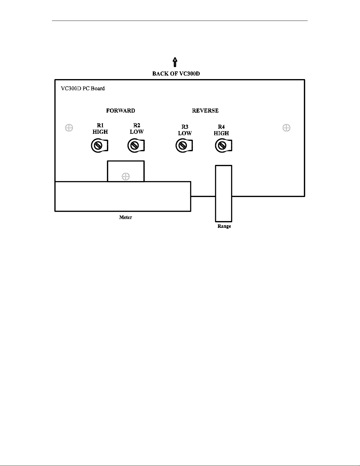
METER CALIBRATION
METER CALIBRATION PEOCEDURE
••••
Connect transceiver to TRANSMITTER IN connector.
••••
Connect external 50Ω load to COAX 2 connector.
••••
Set the OUTPUT SELECT switch to the COAX 2 DIRECT position.
••••
Set the RANGE button to 300 W and the PEAK/AVG button to AVG.
••••
Apply 100W of RF at 14.0 MHz.
••••
Adjust R1 (see Figure 1) so that 100W of FORWARD power is read on the
meter.
••••
Reduce the RF power to 10W and set the RANGE to 30W
••••
Adjust R2 so that 10W of FORWARD power is read on the meter.
••••
Reverse the transceiver and load connectors on the rear panel
••••
Set the RANGE to 300W.
••••
Apply 10W of RF power and adjust R4 to read 10W of REFLECTED power.
••••
Set the RANGE to 30W.
••••
Apply 2W of RF power and adjust R3 to read 2W of REFLECTED power.
9
Page 10
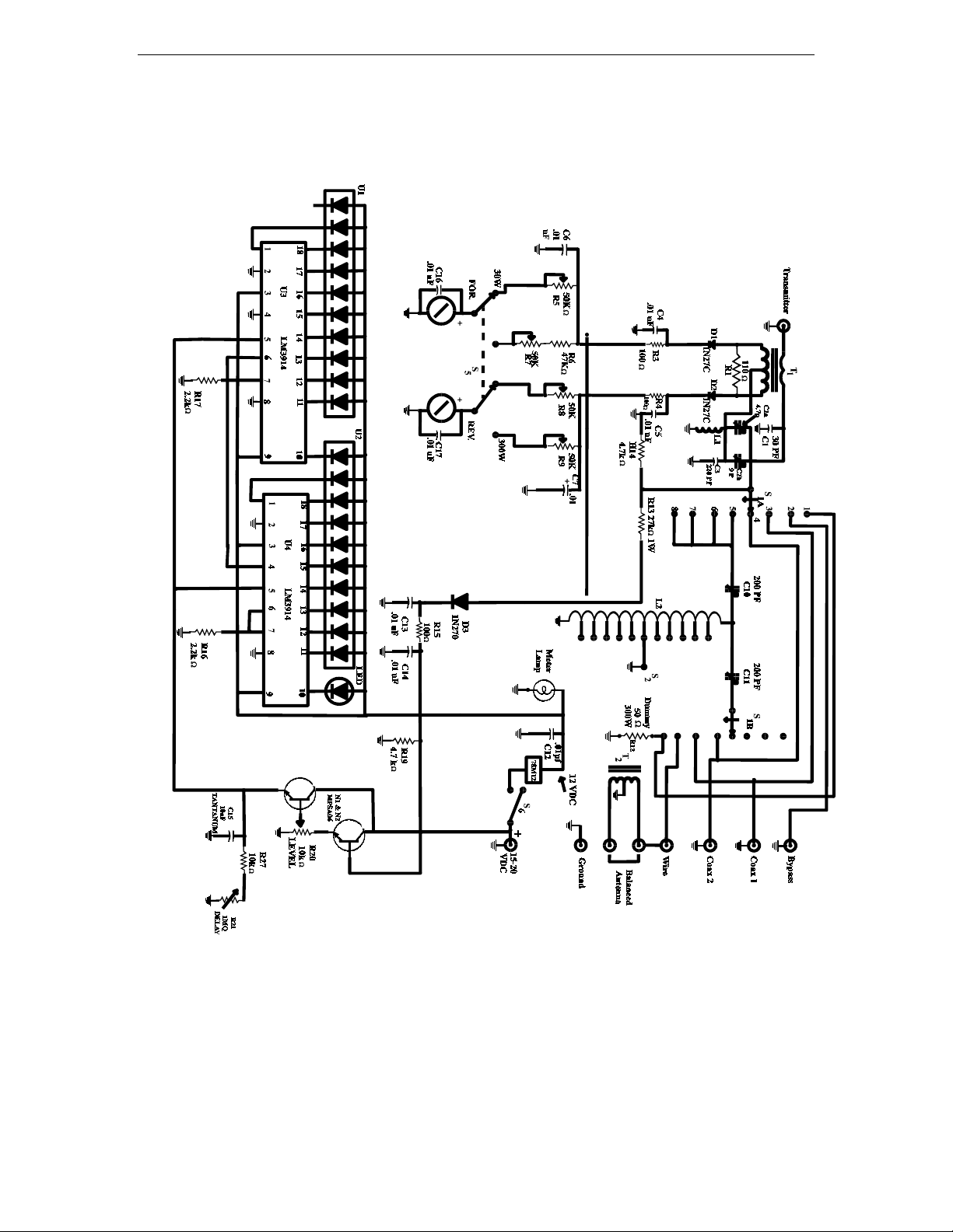
VC-300D Digital Bargraph Antenna Tuner Owner's Manual
SCHEMATIC DIAGRAM
MODEL VC-300D
10
 Loading...